
In the field of gear engineering, hypoid gears are widely used in applications such as automotive rear axles due to their ability to transmit power between non-intersecting shafts with high efficiency and smooth operation. However, traditional design methodologies for hypoid gears have predominantly relied on zero-displacement principles, which include standard and profile-shifted configurations. This approach, while established, limits the potential for optimizing key performance metrics such as strength, wear resistance, noise reduction, and compactness. Drawing inspiration from the concept of “angle displacement” in involute cylindrical gears, we have developed a non-zero displacement design framework for hypoid gears. This innovative method allows for the separation of the pitch circle from the reference circle, enabling tailored adjustments to improve overall performance. Over several years of research, we have established the theoretical foundations, geometric models, computational methods, and practical applications for non-zero displacement hypoid gears. This article delves into the design principles, optimization strategies, and real-world case studies, demonstrating how non-zero displacement can elevate the comprehensive performance of hypoid gear systems.
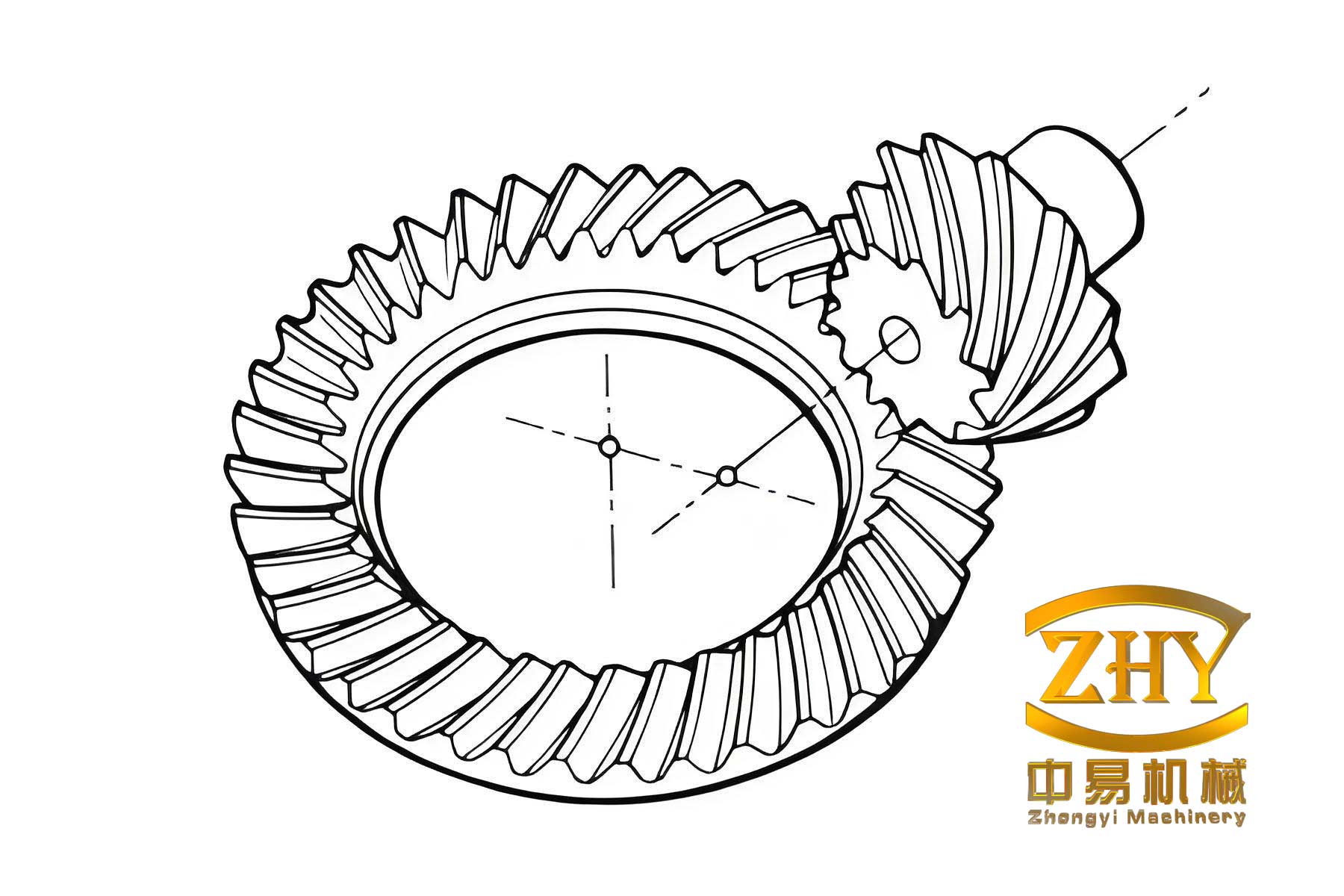
The fundamental principle behind non-zero displacement design for hypoid gears stems from the analogy to crossed helical gear pairs, which serve as imaginary counterparts to hypoid gears. In traditional zero-displacement hypoid gears, the radial displacement coefficient sums to zero, and the tangential displacement coefficient also sums to zero, akin to the characteristics of involute cylindrical gears. However, by introducing non-zero displacement, we can achieve a “relative displacement between the reference cone and the pitch cone,” leading to enhanced control over tooth geometry. This separation allows for adjustments that mitigate issues like root interference, improve load distribution, and reduce sliding velocities on tooth surfaces. The geometric model is based on the kinematic relationships at the meshing point, where the pitch cone and reference cone parameters must satisfy specific equations. For a hypoid gear pair, let us denote the pinion and gear with subscripts 1 and 2, respectively. Key parameters include the reference circle diameter $d$, pitch circle diameter $d’$, normal module at the midpoint $m_n$, spiral angle $\beta$, pressure angle $\alpha$, and shaft angle $\Sigma$. The displacement coefficients are defined as: radial displacement coefficients $x_1$ and $x_2$ for the pinion and gear, and tangential displacement coefficients $x_{t1}$ and $x_{t2}$. The condition for non-zero displacement design is that the sum of radial displacement coefficients is not zero, i.e., $\Sigma x = x_1 + x_2 \neq 0$, and similarly for tangential coefficients if applied. The relationship between reference and pitch circles is given by:
$$ d’ = d + 2x m_n $$
For hypoid gears, this extends to cone distances and angles. The pitch cone angle $\delta’$ is derived from the shaft angle and ratio, while the reference cone angle $\delta$ is adjusted via displacement. The basic equations governing the meshing point are:
$$ \frac{\sin \delta_1′}{\sin \delta_2′} = \frac{z_2}{z_1} $$
and
$$ \Sigma = \delta_1′ + \delta_2′ $$
where $z_1$ and $z_2$ are tooth numbers. With non-zero displacement, the pitch circle diameter $d’$ relates to the reference circle diameter $d$ as:
$$ d’ = d \cdot \frac{\cos \beta}{\cos \beta’} $$
where $\beta’$ is the pitch spiral angle. The displacement coefficients influence tooth dimensions: the addendum $h_a$ and dedendum $h_f$ are modified to maintain standard clearance. The dedendum for pinion and gear are:
$$ h_{f1} = (1 + c^* – x_1) m_n $$
$$ h_{f2} = (1 + c^* – x_2) m_n $$
and addendum are:
$$ h_{a1} = (1 + x_1) m_n $$
$$ h_{a2} = (1 + x_2) m_n $$
where $c^*$ is the clearance coefficient. The total tooth height $h$ remains $h = h_a + h_f = 2.25 m_n$ typically, but can be adjusted. The tangential displacement coefficients affect tooth thickness; the reference circle tooth thickness $s$ is given by:
$$ s = \frac{\pi m_n}{2} + 2 x_t m_n \tan \alpha $$
These geometric adjustments form the basis for optimizing hypoid gear performance. To implement non-zero displacement design effectively, we have developed a computational model that integrates these equations into a comprehensive optimization framework. The goal is to achieve a balanced improvement in multiple performance indicators, such as bending strength, contact strength, wear resistance, and compactness. Our approach involves a two-stage design process: first, a conventional design based on established guidelines to establish baseline parameters; second, an optimization stage where displacement coefficients are fine-tuned using mathematical models. This method leverages existing knowledge while unlocking new potential through non-zero displacement.
The optimization model for hypoid gear comprehensive performance focuses on selecting optimal displacement coefficients. The design variables are:
$$ \mathbf{X} = [x_1, x_2, x_{t1}, x_{t2}]^T $$
where $x_1$ and $x_2$ are radial displacement coefficients for pinion and gear, and $x_{t1}$ and $x_{t2}$ are tangential displacement coefficients. The objective function is a weighted sum of individual performance metrics:
$$ \min \, F(\mathbf{X}) = \mathbf{W}^T \cdot \mathbf{G}(\mathbf{X}) $$
where $\mathbf{W}$ is a weight vector for adjusting priorities, and $\mathbf{G}(\mathbf{X})$ includes functions for volume, bending stress coefficient $K_b$, contact stress coefficient $K_c$, wear coefficient $K_w$, and noise indicators. For hypoid gears, key constraints ensure practical feasibility:
- Bending strength constraint: The bending stress coefficient should not exceed that of the conventional design: $K_b(\mathbf{X}) \leq K_{b0}$.
- Contact strength constraint: The contact stress coefficient should not exceed the baseline: $K_c(\mathbf{X}) \leq K_{c0}$.
- Equal bending strength condition: To balance load, $|K_{b1} – K_{b2}| \leq \epsilon$, where $\epsilon$ is a small tolerance.
- No root interference constraint: Ensure sufficient root clearance: $x_1 \geq x_{1,\min}$ and $x_2 \geq x_{2,\min}$, where minima depend on tooth numbers.
- Tooth tip thickness constraint: Avoid sharp tips: $s_{a1} \geq s_{a,\min}$ and $s_{a2} \geq s_{a,\min}$, typically $s_{a,\min} = 0.25 m_n$.
- Contact ratio constraints: Maintain adequate overlap: $\varepsilon_{\alpha} \geq \varepsilon_{\alpha,\min}$ (transverse contact ratio) and $\varepsilon_{\gamma} \geq \varepsilon_{\gamma,\min}$ (total contact ratio), with common values around 1.2 and 2.0, respectively.
- Displacement coefficient bounds: Practical limits, e.g., $-0.5 \leq x_1, x_2 \leq 0.5$.
This optimization model is compact and adaptable, allowing for iterative refinement based on simulation or experimental data. To illustrate the process, we present a case study involving a hypoid gear pair from an automotive rear axle drive. The baseline design had parameters as shown in Table 1, but suffered from insufficient bending strength and excessive wear in modified vehicle applications. Using non-zero displacement design, we optimized the displacement coefficients while keeping other geometric parameters unchanged. The results, summarized in Table 2, demonstrate significant improvements. The optimization was performed using our in-house software, which implements the geometric calculations and constraint handling. The objective focused on reducing bending stress and wear while maintaining contact strength.
| Parameter | Pinion | Gear |
|---|---|---|
| Tooth number, $z$ | 11 | 41 |
| Shaft angle, $\Sigma$ | 90° | 90° |
| Spiral angle, $\beta$ | 50° | 30° |
| Pressure angle, $\alpha$ | 20° | 20° |
| Module, $m_n$ (mm) | 5.5 | 5.5 |
| Face width (mm) | 38 | 38 |
| Displacement coefficients | $x_1 = 0$, $x_{t1} = 0$ | $x_2 = 0$, $x_{t2} = 0$ |
The optimization yielded new displacement coefficients, leading to recalculated gear dimensions. The performance metrics were evaluated using stress analysis models specific to hypoid gears. For bending stress, we used the Lewis formula adapted for hypoid geometry:
$$ \sigma_b = \frac{F_t}{b m_n} K_b $$
where $F_t$ is tangential force, $b$ is face width, and $K_b$ is a bending factor incorporating geometry and load distribution. For contact stress, the Hertzian model was applied:
$$ \sigma_c = \sqrt{\frac{F_t E^*}{b \rho_c}} K_c $$
where $E^*$ is equivalent modulus, and $\rho_c$ is relative curvature. Wear was assessed based on sliding velocity and pressure. The optimization results are shown in Table 2.
| Metric | Baseline Design | Optimized Non-Zero Design | Improvement |
|---|---|---|---|
| Radial displacement coefficients: $x_1$, $x_2$ | 0, 0 | 0.15, -0.10 | N/A |
| Tangential displacement coefficients: $x_{t1}$, $x_{t2}$ | 0, 0 | 0.05, -0.05 | N/A |
| Bending stress coefficient, $K_b$ | 1.00 | 0.85 | 15% reduction |
| Contact stress coefficient, $K_c$ | 1.00 | 0.95 | 5% reduction |
| Wear coefficient, $K_w$ | 1.00 | 0.78 | 22% reduction |
| Volume index | 1.00 | 0.98 | 2% reduction |
These numerical improvements were validated through bench testing, where the optimized hypoid gear pair showed enhanced durability and lower operating temperatures. The non-zero displacement design allowed for better load sharing and reduced stress concentrations, which are critical for hypoid gears in high-torque applications. Furthermore, the adjustment of tooth geometry led to a more favorable contact pattern, minimizing edge loading and improving efficiency. This case study underscores the practicality of non-zero displacement design for hypoid gears, offering a cost-effective way to upgrade existing systems without altering housing dimensions.
Beyond this application, the non-zero displacement methodology can be extended to other hypoid gear scenarios, such as industrial drives or aerospace systems. The geometric model we developed is general and can be integrated into CAD/CAE tools for automated design. Key formulas for hypoid gear geometry with non-zero displacement include the calculation of pitch cone angles:
$$ \delta_1′ = \arctan\left(\frac{\sin \Sigma}{\frac{z_2}{z_1} + \cos \Sigma}\right) $$
and
$$ \delta_2′ = \Sigma – \delta_1′ $$
The reference cone angles $\delta_1$ and $\delta_2$ are adjusted using displacement coefficients via an iterative process to satisfy meshing constraints. The tooth thickness modification due to tangential displacement is crucial for backlash control; the effective tooth thickness on the pitch circle is:
$$ s’ = s \frac{d’}{d} $$
where $s$ is the reference circle tooth thickness. For hypoid gears, the sliding velocity $v_s$ at the meshing point influences wear and efficiency; it can be expressed as:
$$ v_s = v_1 – v_2 $$
where $v_1$ and $v_2$ are surface velocities of pinion and gear. Non-zero displacement can reduce $v_s$ by optimizing the contact path. Additionally, the contact ratio for hypoid gears is complex due to the hyperbolic geometry; we approximate it using the transverse contact ratio $\varepsilon_{\alpha}$ and the overlap ratio $\varepsilon_{\beta}$ from spiral angle. The total contact ratio is:
$$ \varepsilon_{\gamma} = \varepsilon_{\alpha} + \varepsilon_{\beta} $$
where $\varepsilon_{\alpha} = \frac{\sqrt{d_{a1}^2 – d_{b1}^2} + \sqrt{d_{a2}^2 – d_{b2}^2} – a \sin \alpha_t}{p_t}$, with $d_a$ as addendum diameter, $d_b$ base diameter, $a$ center distance, and $p_t$ transverse pitch. These formulas are embedded in our software to evaluate each design iteration.
In terms of implementation, machining non-zero displacement hypoid gears requires adjustments to tool settings. Traditional hypoid gear generators, such as Gleason machines, can accommodate this by modifying the machine-tool geometry relationships. The basic principle involves offsetting the cutter relative to the gear blank according to the displacement coefficients. For example, the radial displacement $x$ translates to a cutter shift, while tangential displacement $x_t$ adjusts the cutter phase. Our research has developed algorithms to convert displacement coefficients into machine settings, ensuring accurate tooth flank generation. This makes non-zero displacement design feasible for mass production without significant retooling costs.
Looking forward, the adoption of non-zero displacement design for hypoid gears opens avenues for further research. Topics include dynamic performance optimization, noise-vibration-harshness (NVH) reduction, and integration with lightweight materials. The flexibility of this approach allows designers to tailor hypoid gears for specific operating conditions, whether it’s for electric vehicles requiring high efficiency or heavy machinery demanding extreme durability. Moreover, advancements in additive manufacturing could enable complex tooth geometries that fully leverage non-zero displacement benefits.
To summarize, non-zero displacement design represents a paradigm shift in hypoid gear engineering. By moving beyond traditional zero-displacement constraints, we can unlock superior performance characteristics. Our work has established a robust framework encompassing theory, computation, and practice. The key takeaways are: (1) Non-zero displacement allows for independent control of pitch and reference circles, enabling optimization of strength and wear. (2) A systematic optimization model with displacement coefficients as variables can balance multiple performance goals. (3) Practical applications, such as automotive rear axles, demonstrate tangible improvements in bending strength, contact stress, and wear resistance. As the demand for efficient and reliable power transmission grows, non-zero displacement design will play an increasingly vital role in advancing hypoid gear technology. We encourage engineers and researchers to explore this methodology and contribute to its evolution for future generations of hypoid gear systems.