
I study gear machining of spiral bevel gears because these components combine smooth transmission, high load capacity, and strong kinematic stability, yet their final precision and surface integrity depend heavily on the last grinding operation. In my view, gear machining is not only a geometric shaping process but also a coupled thermal-mechanical process. When the grinding wheel removes a thin layer from a hardened tooth flank, almost all of the consumed mechanical energy is converted into heat. This heat is generated inside a very small contact zone, and if it is not conducted, convected, or carried away quickly, the tooth surface can reach temperatures high enough to cause oxidation, tempering, softening, burn marks, and even micro-cracks. Therefore, I developed an analysis method that combines gear geometry, metal cutting theory, heat source theory, and finite element computation to predict the grinding temperature field of spiral bevel gears during the entire gear machining cycle.
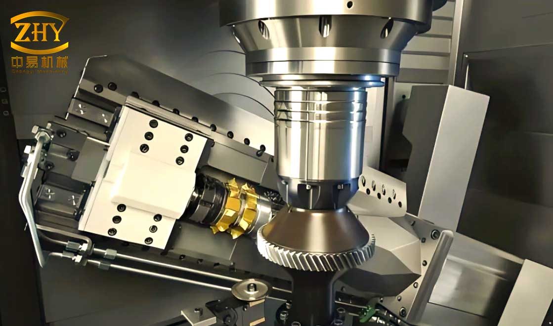
My method follows a hybrid analytical-numerical route. I first identify the grinding contact condition from the meshing kinematics of the generating wheel and the workpiece. I then discretize the three-dimensional contact zone into slices, evaluate the local grinding force and heat flux, estimate the heat partition among the workpiece, wheel, chips, and fluid, and finally solve the transient heat conduction problem by the finite element method. In this way, I can predict the temperature history at any tooth surface point and determine the burn-risk region for different process parameters. The analysis is intended to support parameter selection, improve gear machining quality, and reduce trial-and-error in production.
Gear machining principle and relative motion. In spiral bevel gear grinding, the grinding wheel plays the role of a virtual generating gear or a forming tool. When I use the generating method, the wheel and the workpiece perform a coordinated generating motion. The cutting surface of the wheel represents one tooth of the virtual generating gear, and the instantaneous contact between the wheel and the tooth flank is a line. As the generating motion continues, these instantaneous contact lines sweep the whole tooth surface. When I use the forming method, the wheel profile directly corresponds to the tooth profile. The wheel axis and the workpiece axis have no relative generating motion in the classical sense. Instead, the wheel plunges into the tooth slot, and the contact region can cover a large part of the flank. Because this condition can trap heat and chips, a Waguri mechanism is often introduced. The eccentric spindle makes the wheel move back and forth slightly, so the two flanks are ground alternately and the fluid can enter the contact zone more easily.
| Feature | Generating method | Forming method |
|---|---|---|
| Tool representation | Virtual generating gear | Direct profile copying |
| Contact form | Line contact and sweeping | Large-area or full-flank contact |
| Relative motion | Rolling and generating motion | Plunge motion plus eccentric oscillation |
| Typical application | Pinion with smaller cone angle | Wheel with larger cone angle |
| Thermal risk | Concentrated near root line | More uniform but sensitive to fluid access |
| Cooling strategy | Moving heat source with fluid convection | Alternating flank contact by Waguri mechanism |
For gear machining, I define the machine coordinate system, the cutter or wheel coordinate system, the generating gear coordinate system, and the workpiece coordinate system. The transformation between these systems is expressed by rotation matrices. For example, the rotation matrix about the x-axis is
$$ M_x(\alpha)=\begin{bmatrix}1&0&0\\0&\cos\alpha&\sin\alpha\\0&-\sin\alpha&\cos\alpha\end{bmatrix} $$
the rotation matrix about the y-axis is
$$ M_y(\alpha)=\begin{bmatrix}\cos\alpha&0&-\sin\alpha\\0&1&0\\\sin\alpha&0&\cos\alpha\end{bmatrix} $$
and the rotation matrix about the z-axis is
$$ M_z(\alpha)=\begin{bmatrix}\cos\alpha&\sin\alpha&0\\-\sin\alpha&\cos\alpha&0\\0&0&1\end{bmatrix} $$
Using these matrices, I transform the wheel edge tangent, normal, radius vector, and axis direction into the generating gear frame. The edge geometry of the wheel can be written as a function of the blade phase angle. For a point on the cutting edge, the tangent vector, normal vector, and radius vector are represented in the tool frame. After two successive rotations, the same vectors are expressed in the generating gear frame. The tooth surface point of the spiral bevel gear is then obtained by adding the wheel position vector and the distance along the cutting edge.
Tooth surface equation and discretization. I derive the tooth surface equation from the meshing condition. Let the generating surface be defined by parameters \(q_r\) and \(\varphi\). The radius vector of a point on the generating surface in the machine frame can be written as
$$ \mathbf{R}_{br}=\mathbf{D}_{rr}+\mathbf{A}_{cr}+b_{tr}\mathbf{t}_{r} $$
where \(\mathbf{D}_{rr}\) is the vector from the machine origin to the workpiece axis, \(\mathbf{A}_{cr}\) is the cutter tip vector after rotation about the generating axis, \(b_{tr}\) is the distance along the cutting edge, and \(\mathbf{t}_{r}\) is the unit tangent of the cutting edge. For the generating method, \(b_{tr}\) is not independent; it is determined by the meshing equation. For the forming method, \(b_{tr}\) is an independent parameter that defines the contact point along the blade. The meshing equation for the generating method can be written in the form
$$ b_{tr}=\frac{\left(\mathbf{v}_{r}-\mathbf{v}_{cr}\right)\cdot\left(\mathbf{n}_{r}\times\mathbf{p}_{r}\right)+\mathbf{g}_{r}\cdot\left(\mathbf{D}_{rr}+\mathbf{A}_{cr}\right)}{\left(\mathbf{n}_{r}\times\mathbf{p}_{r}\right)\cdot\mathbf{t}_{r}} $$
where \(\mathbf{v}_{r}\) and \(\mathbf{v}_{cr}\) are the velocity vectors of the generating surface and the cutter, \(\mathbf{n}_{r}\) is the unit normal, \(\mathbf{p}_{r}\) is the unit vector along the workpiece axis, and \(\mathbf{g}_{r}\) is the unit vector opposite to the machine vertical direction. Once the parameters are known, the tooth surface point is projected onto the axial section of the gear. I denote the longitudinal coordinate by \(L_r\) and the radial coordinate by \(R_{br}\). For the generating method,
$$ L_r=L_r(q_r,\varphi),\qquad R_{br}=|\mathbf{R}_{br}\times\mathbf{p}_r| $$
and for the forming method,
$$ L_r=L_r(b_{tr},\varphi),\qquad R_{br}=|\mathbf{R}_{br}\times\mathbf{p}_r| $$
Because the spiral bevel gear tooth surface is a free-form surface without a simple elementary expression, I discretize it numerically. I first determine the theoretical tooth surface boundary, then shrink the boundary slightly inward to avoid non-convergence near the edges. The shrink amounts at the toe, top, heel, and root are denoted by \(d_1\), \(d_2\), \(d_3\), and \(d_4\). I divide the shrunk boundary into \(m\) segments along the tooth length and \(n\) segments along the tooth height. This produces \(m\times n\) grid points. After solving the tooth surface equation at each grid point, I fit the points with spline surfaces to obtain a smooth three-dimensional gear model for gear machining analysis.
Instantaneous contact line and local geometry. In the generating method, the instantaneous contact line is determined by the generating roll angle \(q_r\) and the blade phase angle \(\varphi\). The contact line may intersect the tooth surface boundary in different ways. To decide whether a computed point lies inside the theoretical tooth surface, I use the boundary line functions \(L_1=f_1(x)\), \(L_2=f_2(x)\), \(L_3=f_3(x)\), and \(L_4=f_4(x)\). The point \((L,R)\) belongs to the useful tooth surface only if
$$ R\ge f_1(L),\qquad R\le f_2(L),\qquad R\le f_3(L),\qquad R\ge f_4(L) $$
This condition removes spurious points that lie outside the physical tooth surface during gear machining simulation. At any meshing point on the instantaneous contact line, I establish a local coordinate frame with axes along the tangent, normal, and binormal directions. I then compute the relative angular velocity \(\boldsymbol{\omega}_{12}\), relative velocity \(\mathbf{V}_{12}\), and relative acceleration \(\mathbf{a}_{12}\). Using the Baxter formulas, I obtain the normal curvatures \(K_{tx}^{12}\), \(K_{ty}^{12}\) and the geodesic torsion \(G_{tx}^{12}\). These quantities are essential because they define the local shape of the contact zone and the pressure distribution in gear machining.
The relative curvature in any direction \(\theta\) is evaluated by the Euler formula. If the principal curvatures are \(k_1\) and \(k_2\), and the geodesic torsion along the first principal direction is \(g_1\), then
$$ k_n(\theta)=k_1\cos^2\theta+2g_1\sin\theta\cos\theta+k_2\sin^2\theta $$
and the corresponding geodesic torsion is
$$ \tau_g(\theta)=(k_2-k_1)\sin\theta\cos\theta+g_1(\cos^2\theta-\sin^2\theta) $$
I use these relationships to build a local quadratic surface that approximates the gap between the wheel and the workpiece. The quadratic surface is
$$ z=\frac{1}{2}K_x x^2+G_{xy}xy+\frac{1}{2}K_y y^2 $$
where \(K_x\) and \(K_y\) are the relative normal curvatures and \(G_{xy}\) is the relative geodesic torsion. This fitted surface allows me to describe the shape of the grinding contact zone without solving the full three-dimensional elasticity problem at every instant. It is especially useful for gear machining because the contact zone changes continuously along the tooth flank.
| Quantity | Symbol | Role in gear machining |
|---|---|---|
| Generating roll angle | \(q_r\) | Defines the instantaneous generating position |
| Blade phase angle | \(\varphi\) | Locates a point on the cutting edge |
| Distance along edge | \(b_{tr}\) | Meshing parameter or independent forming parameter |
| Normal curvature | \(K_x,K_y\) | Controls contact ellipse and pressure distribution |
| Geodesic torsion | \(G_{xy}\) | Controls twisting of the contact zone |
| Contact arc length | \(l_g\) | Controls local heat flux and force density |
Grinding contact zone in the generating method. For the generating method, I treat the wheel and the workpiece as two elastic bodies in line contact. At each point on the instantaneous contact line, I extract a small slice perpendicular to the contact line. The intersection of the fitted quadratic surface with a plane parallel to the grinding velocity gives a curve that represents the local removed area. If the grinding depth is \(h_z\), the curve is shifted downward by \(h_z\). The contact arc length is then
$$ l_g=g_1(y=0)-g_2(y=0) $$
where \(g_1(y)\) is the original curve and \(g_2(y)\) is the shifted curve. The contact area of the slice is obtained by integrating the difference between the two curves:
$$ S_g=\int_{L_s}\left[g_1(y)-g_2(y)\right]dy $$
This slice-based approach is efficient for gear machining simulation because the three-dimensional contact zone is reconstructed from a series of two-dimensional slices. I can therefore evaluate the local grinding force and heat flux without meshing the entire wheel-workpiece interface at every time step.
Grinding contact zone in the forming method. For the forming method, the wheel profile matches the tooth profile, so the contact area is much larger. I analyze the motion of the Waguri mechanism to determine the actual contact depth at each instant. Let the eccentric radius be \(e\), the rotation speed be \(n_w\), and the angular position be \(\alpha_t\). The reciprocating velocity caused by the eccentric spindle is
$$ V_{wi}=V_{fw}\sin\alpha_t,\qquad V_{fw}=2\pi e n_w $$
The feed velocity along the tooth height is \(V_z\). If the total depth is \(Z_c\), the depth removed during one contact for the concave flank can be approximated as
$$ Z_{ai}=\frac{V_z t}{h_c}\cos\alpha_a $$
and for the convex flank as
$$ Z_{bi}=\frac{V_z t}{h_c}\cos\alpha_b $$
where \(\alpha_a\) and \(\alpha_b\) are the outer and inner blade pressure angles, and \(h_c\) is the total feed length. Because the two flanks are ground alternately, the heat load on each flank is intermittent. This intermittent contact is beneficial for gear machining because it gives the fluid a chance to cool the surface and carry away chips. However, if the eccentric speed is too high, the cooling interval becomes too short, and the surface temperature can still accumulate.
| Parameter | Meaning in forming method | Thermal consequence |
|---|---|---|
| \(e\) | Eccentric radius of Waguri spindle | Controls alternating flank contact |
| \(n_w\) | Waguri rotation speed | Higher speed reduces cooling interval |
| \(V_z\) | Feed velocity along tooth height | Higher feed increases removed depth per contact |
| \(\alpha_a,\alpha_b\) | Outer and inner blade angles | Control asymmetric depth on two flanks |
| \(Z_c\) | Total grinding depth | Controls total heat input per cycle |
Grinding force model. I model the grinding force by dividing the interaction between a single abrasive grain and the workpiece into three stages: rubbing, plowing, and chip formation. The normal force per unit width is
$$ F_n’=F_{nch}’+F_{npl}’+F_{nsl}’ $$
and the tangential force per unit width is
$$ F_t’=F_{tch}’+F_{tpl}’+F_{tsl}’ $$
The chip formation component is related to the specific chip formation energy \(u_{ch}\), the workpiece feed velocity \(v_w\), the wheel speed \(v_s\), and the equivalent grinding depth \(a’\):
$$ F_{nch}’=k_{ch}\frac{u_{ch}v_w a’}{v_s},\qquad F_{tch}’=\frac{u_{ch}v_w a’}{v_s} $$
The plowing component is proportional to the tangential plowing force:
$$ F_{npl}’=k_{pl}F_{tpl}’ $$
The sliding component depends on the real contact area between the flattened abrasive grains and the workpiece. If \(A_g\) is the flattened grain area, \(b\) is the contact width, \(l_k\) is the sliding contact length, and \(p_c\) is the average contact pressure, then
$$ F_{nsl}’=p_c A_g b l_k,\qquad F_{tsl}’=\mu F_{nsl}’ $$
The average contact pressure is expressed as
$$ p_c=k_{sl}r_k,\qquad r_k=\sqrt{\frac{4v_w}{d_s’v_s}} $$
where \(k_{sl}\) is the sliding coefficient, \(r_k\) is the relative contact ratio, and \(d_s’\) is the equivalent wheel diameter. The equivalent diameter accounts for the curvature of the tooth surface in the grinding direction:
$$ d_s’=\frac{d_s d_w}{d_s+d_w} $$
Combining these terms, I obtain the normal and tangential force intensities for a single-grain plane grinding model:
$$ F_n’=\frac{u_{ch}v_w a’}{v_s}+k_{pl}F_{tpl}’+k_{sl}\sqrt{\frac{4v_w}{d_s’v_s}}A_g b l_k $$
$$ F_t’=\frac{u_{ch}v_w a’}{v_s}+F_{tpl}’+\mu k_{sl}\sqrt{\frac{4v_w}{d_s’v_s}}A_g b l_k $$
For the generating method, I integrate these force intensities along the instantaneous contact line. The total grinding force at a given instant is
$$ \mathbf{F}_G=\int_L\left(\mathbf{F}_{gn}+\mathbf{F}_{gt}\right)ds $$
For the forming method, I estimate the number of active grains on the inner and outer flanks. If the total number of grains on the inner flank is \(N_1\), the total number on the outer flank is \(N_2\), and the contact angle is \(\alpha\), then
$$ N_a=N_1\frac{\alpha}{2\pi},\qquad N_b=N_2\frac{\alpha}{2\pi} $$
The total forces on the two flanks are
$$ \mathbf{F}_{fa}=N_a\left(\mathbf{F}_n’+\mathbf{F}_t’\right),\qquad \mathbf{F}_{fb}=N_b\left(\mathbf{F}_n’+\mathbf{F}_t’\right) $$
These force expressions are used in the thermal model because the heat flux is proportional to the product of force and sliding velocity. In gear machining, the force varies along the contact line in the generating method and across the flank in the forming method, so the heat input is never perfectly uniform.
| Force component | Physical origin | Main influencing variables |
|---|---|---|
| \(F_{nch}’,F_{tch}’\) | Chip formation | \(u_{ch},v_w,a’,v_s\) |
| \(F_{npl}’,F_{tpl}’\) | Plowing | \(k_{pl},F_{tpl}’\) |
| \(F_{nsl}’,F_{tsl}’\) | Sliding and rubbing | \(A_g,b,l_k,\mu,r_k\) |
| \(\mathbf{F}_G\) | Integrated line force | Contact line shape and local depth |
| \(\mathbf{F}_{fa},\mathbf{F}_{fb}\) | Forming flank forces | Active grain number and contact angle |
Heat source and heat flux density. I adopt the moving heat source concept for gear machining. The grinding zone is treated as a band heat source moving along the tooth surface. Because the chip thickness is not uniform along the contact arc, a triangular heat flux distribution is more realistic than a rectangular one. I therefore assume that the heat flux increases from the leading edge to the trailing edge of the contact zone. The moving heat source solution is based on the Jaeger model. For a band source of length \(l_c\), the temperature at a point \((y,z)\) below the surface is
$$ T(y,z)=\int_0^{l_c}\frac{q(\xi)}{2\pi k}\exp\left[-\frac{v(y-\xi)}{2\alpha}\right]K_0\left[\frac{v\sqrt{(y-\xi)^2+z^2}}{2\alpha}\right]d\xi $$
where \(q(\xi)\) is the local heat flux, \(k\) is the thermal conductivity, \(\alpha\) is the thermal diffusivity, \(v\) is the source velocity, and \(K_0\) is the modified Bessel function of the second kind. For a triangular distribution, \(q(\xi)\) can be written as
$$ q(\xi)=q_{\max}\frac{\xi}{l_c},\qquad 0\le\xi\le l_c $$
This distribution produces a sharper temperature peak near the trailing edge, which agrees better with measured grinding temperatures in gear machining.
Heat partition ratio. The total heat generated in the grinding zone is distributed among the workpiece, the wheel, the chips, and the grinding fluid. I write the energy balance as
$$ Q_t=q_w+q_s+q_f+q_{ch} $$
Each term can be related to the maximum contact temperature \(T_{\max}\). For the workpiece, wheel, fluid, and chips,
$$ Q_t=h_w T_{\max}+h_s T_{\max}+\alpha T_{\max}+h_{ch}T_{\max} $$
The workpiece heat transfer coefficient is estimated from the classical moving-source expression
$$ h_w=\sqrt{\frac{k_w\rho_w c_w v_w}{C l_g}} $$
where \(k_w\), \(\rho_w\), and \(c_w\) are the thermal conductivity, density, and specific heat of the workpiece, and \(C\) is a surface temperature coefficient. The chip heat flux is related to the specific grinding energy and the melting temperature:
$$ q_{ch}=\frac{p_w c_w T_{mp} z v_s}{S} $$
where \(T_{mp}\) is the melting temperature, \(z\) is the grinding depth, and \(S\) is the contact area. For the wheel-fluid composite, I use the following corrected partition ratio:
$$ R_w=\frac{q_w}{q_w+q_s}=\left[1+\frac{0.974k_g}{k_w\rho_w c_w r_g v_s}\right]^{-1} $$
This expression shows that the fraction of heat entering the workpiece decreases when the wheel speed increases, when the wheel conductivity increases, or when the workpiece thermal effusivity increases. For wet grinding, the heat carried away by the fluid is
$$ q_{wf}=q_w+q_f=\left(Q_t-q_{ch}\right)R_w $$
and for dry grinding, the heat entering the workpiece is
$$ q_w=R_wQ_t $$
I use these quantities as boundary conditions in the finite element model. In gear machining, the partition ratio is not a constant; it changes with local contact geometry, wheel wear, fluid supply, and material properties. My model therefore updates the partition ratio at each load step.
| Heat sink | Symbol | Main mechanism | Typical effect in gear machining |
|---|---|---|---|
| Workpiece | \(q_w\) | Conduction into tooth flank | Controls burn depth and residual stress |
| Wheel | \(q_s\) | Conduction into abrasive and bond | Reduces workpiece temperature |
| Fluid | \(q_f\) | Convection and film boiling | Strongly lowers wet grinding temperature |
| Chips | \(q_{ch}\) | Heat carried by removed material | More important at high removal rate |
Heat flux calculation. For the generating method, I integrate the product of grinding force and wheel speed along the instantaneous contact line. The total heat flux entering the contact zone is
$$ Q_1=\int_L\frac{\mathbf{F}_{gn}\cdot\mathbf{v}_s+\mathbf{F}_{gt}\cdot\mathbf{v}_s}{S l_z}ds $$
where \(S\) is the local contact area and \(l_z\) is the slice length. For the forming method, I sum the contribution of all active grains:
$$ Q_2=\sum_{a,b}N_{a,b}\frac{\mathbf{F}_{fa,b}\cdot\mathbf{v}_s}{l_a l_b \pi} $$
These heat fluxes are then multiplied by the workpiece partition ratio \(R_w\) and applied to the finite element mesh. In the generating method, the heat flux is concentrated near the root line and moves along the tooth length. In the forming method, the heat flux is distributed over the whole flank and alternates between the concave and convex sides.
Finite element formulation of the temperature field. I assume that the grinding fluid is uniformly distributed in wet grinding, the initial temperature of the gear and air is \(25^\circ\mathrm{C}\), and the material properties vary with temperature. The contact area is treated as a moving heat source. The gear surfaces outside the contact zone exchange heat with air or fluid by convection. The transient heat conduction equation for the gear body is
$$ \frac{\partial}{\partial x}\left(k_x\frac{\partial T}{\partial x}\right)+\frac{\partial}{\partial y}\left(k_y\frac{\partial T}{\partial y}\right)+\frac{\partial}{\partial z}\left(k_z\frac{\partial T}{\partial z}\right)+q_v=\rho c\frac{\partial T}{\partial t} $$
I consider three types of boundary conditions. The first kind specifies the surface temperature:
$$ T=T_1 $$
The second kind specifies the heat flux:
$$ k_x n_x\frac{\partial T}{\partial x}+k_y n_y\frac{\partial T}{\partial y}+k_z n_z\frac{\partial T}{\partial z}=q $$
The third kind specifies convection:
$$ k_x n_x\frac{\partial T}{\partial x}+k_y n_y\frac{\partial T}{\partial y}+k_z n_z\frac{\partial T}{\partial z}=\alpha\left(T-T_f\right) $$
In my gear machining model, the grinding contact zone is governed by the second kind, and the remaining surfaces are governed by the third kind. For wet grinding, a duplicate surface layer is created on the contact zone so that both heat flux and convection can be applied without conflict.
I discretize the gear body into finite elements. The temperature inside an element is interpolated from nodal temperatures:
$$ T(x,y,z,t)=\sum_{i=1}^{n_e}N_i(x,y,z)T_i(t) $$
Using the weighted residual method, I obtain the transient finite element equation
$$ C\dot{T}+KT=P $$
where \(C\) is the heat capacity matrix, \(K\) is the conductivity matrix, \(T\) is the nodal temperature vector, and \(P\) is the thermal load vector. The element matrices are
$$ K_{ij}^e=\int_{\Omega^e}\left(k_x\frac{\partial N_i}{\partial x}\frac{\partial N_j}{\partial x}+k_y\frac{\partial N_i}{\partial y}\frac{\partial N_j}{\partial y}+k_z\frac{\partial N_i}{\partial z}\frac{\partial N_j}{\partial z}\right)d\Omega $$
$$ C_{ij}^e=\int_{\Omega^e}\rho c N_i N_j d\Omega $$
$$ H_{ij}^e=\int_{\Gamma_3^e}\alpha N_i N_j d\Gamma $$
$$ P_{qi}^e=\int_{\Gamma_2^e}qN_i d\Gamma $$
$$ P_{Hi}^e=\int_{\Gamma_3^e}\alpha T_f N_i d\Gamma $$
The global matrices are assembled from the element matrices. The time integration is performed by dividing the entire gear machining cycle into a sequence of load steps. Each load step corresponds to a small interval of wheel motion. At the end of each step, the heat flux boundary is removed and reapplied at the new contact location. The temperature field from the previous step becomes the initial condition for the next step. This procedure captures the thermal history of the tooth surface as the wheel sweeps along the flank.
| Model component | Mathematical tool | Purpose in gear machining |
|---|---|---|
| Tooth surface | Meshing equation and spline fitting | Provides exact geometry for heat source location |
| Contact zone | Quadratic surface and slice method | Defines local contact area and arc length |
| Grinding force | Single-grain plane grinding model | Provides mechanical energy input |
| Heat source | Jaeger moving source and triangular distribution | Defines spatial heat flux |
| Heat partition | Composite wheel-fluid model | Separates heat entering each medium |
| Temperature field | Transient finite element method | Predicts temperature history and burn risk |
Material and process data. I use a representative spiral bevel gear pair in my analysis. The wheel is ground by the forming method, and the pinion is ground by the generating method. The gear material is a carburizing steel, the abrasive is brown alumina, and the fluid is a water-based emulsion. The thermal properties change with temperature, so I update them during the transient solution. The main gear parameters are listed below.
| Parameter | Wheel | Pinion |
|---|---|---|
| Number of teeth | 41 | 11 |
| Module | 4.024 mm | 4.024 mm |
| Shaft angle | \(90^\circ\) | \(90^\circ\) |
| Offset distance | 23.00 mm | 23.00 mm |
| Face width | 26.00 mm | 29.78 mm |
| Hand | Left | Right |
| Pressure angle | \(38^\circ\) | \(38^\circ\) |
| Thermal property | Water-based fluid | Carburizing steel | Alumina wheel |
|---|---|---|---|
| Thermal conductivity \(W/(m\cdot K)\) | 0.68 | 40 | 35 |
| Density \(kg/m^3\) | 1000 | 7900 | 3980 |
| Specific heat \(J/(kg\cdot K)\) | 4180 | 460 | 765 |
| Thermal contact coefficient \(J/(m^2s^{0.5}K)\) | 1686 | 12057 | 10300 |
| Process | Wheel speed | Feed speed | Grinding depth | Fluid |
|---|---|---|---|---|
| Generating method | 31.4 m/s | 1000 mm/min | 0.05 mm | Water-based emulsion |
| Forming method | 31.4 m/s | 20 mm/min | 0.10 mm | Water-based emulsion |
Temperature field results and burn validation. After solving the transient finite element model, I obtain the temperature distribution on the tooth surface at every load step. For the generating method, the high-temperature region appears near the root line and has an irregular elliptical shape. The maximum temperature occurs inside the contact zone and moves with the wheel. For the forming method, the temperature is more uniformly distributed over the flank, and the two flanks are heated alternately. In wet grinding, the maximum temperature is much lower because the fluid removes a large fraction of the heat. In dry grinding, the temperature continues to accumulate and can exceed the burn threshold.
The burn threshold for the carburizing steel used in my analysis is approximately \(600^\circ\mathrm{C}\). When the calculated temperature exceeds this value, the material is considered to be at risk of thermal damage. For the generating method, the burn-risk zone is concentrated near the root line. This agrees with experimental observations that root regions are often more susceptible to grinding burn in gear machining. For the forming method, the burn risk is less localized, but the overall temperature level can be higher if the fluid cannot reach the contact zone. The Waguri mechanism improves cooling by alternating the contact, but excessive rotational speed shortens the cooling interval and raises the average temperature.
| Condition | Maximum temperature trend | Burn risk region | Recommended action |
|---|---|---|---|
| Generating, dry | High and localized | Near root line | Reduce depth or use fluid |
| Generating, wet | Lower and more stable | Small near root line | Use high speed and small depth |
| Forming, dry | High and accumulating | Broad flank area | Use fluid and lower feed |
| Forming, wet | Moderate and intermittent | Weakly localized | Optimize Waguri speed |
Influence of grinding depth. I studied the effect of grinding depth on the maximum temperature. For the generating method, the maximum temperature increases nonlinearly with depth. When the depth exceeds about \(0.08\ \mathrm{mm}\), the temperature rise becomes steeper because the contact area and heat partition ratio change rapidly. In dry grinding, the depth should not exceed \(0.10\ \mathrm{mm}\) if burn is to be avoided. In wet grinding, the limit is about \(0.13\ \mathrm{mm}\). Therefore, I recommend a rough grinding depth of \(0.05\ \mathrm{mm}\) and a finishing depth between \(0.01\) and \(0.03\ \mathrm{mm}\). For the forming method, the temperature rises more slowly with depth because the contact area does not grow as sharply. A rough depth of \(0.03\ \mathrm{mm}\) and a finishing depth of \(0.01\) to \(0.02\ \mathrm{mm}\) are practical for gear machining.
| Method | Condition | Critical depth | Recommended rough depth | Recommended finish depth |
|---|---|---|---|---|
| Generating | Dry | 0.10 mm | 0.03–0.05 mm | 0.01–0.03 mm |
| Generating | Wet | 0.13 mm | 0.05 mm | 0.01–0.03 mm |
| Forming | Dry | 0.05 mm | 0.02–0.03 mm | 0.01–0.02 mm |
| Forming | Wet | 0.07 mm | 0.03 mm | 0.01–0.02 mm |
Influence of wheel speed. In the generating method, the maximum temperature decreases as the wheel speed increases. The decrease is not linear; it becomes smaller at very high speeds. The reason is that a higher wheel speed reduces the average chip thickness and the friction coefficient, so the specific grinding energy decreases. The abrasive grains also remove material more efficiently, which reduces the force per grain. In the forming method, dry grinding shows a decrease followed by a plateau, while wet grinding continues to decrease. The plateau in dry grinding occurs because the contact conditions reach a limit where the friction coefficient no longer drops significantly. For gear machining, increasing the wheel speed is generally beneficial for surface quality, provided that the machine spindle and cooling system can support it.
Influence of feed speed. In the generating method, the maximum temperature decreases slightly as the feed speed increases. A higher feed speed reduces the time during which the heat source acts on a given surface point. The fluid also has more relative time to remove heat before the next pass. However, if the feed speed is too high, the dynamic stability of the gear machining process may degrade, and the actual depth of cut may become uneven. In the forming method, the feed speed along the tooth height has the opposite effect: a higher feed speed increases the removed depth per contact, so the grinding force and temperature both increase. Therefore, the feed speed must be selected together with the grinding depth and the Waguri speed.
| Parameter | Generating method effect | Forming method effect | Practical recommendation |
|---|---|---|---|
| Grinding depth | Strongly increases temperature | Moderately increases temperature | Use small depth and multiple passes |
| Wheel speed | Decreases temperature | Decreases then plateaus | Use high speed within machine limits |
| Feed speed | Slightly decreases temperature | Increases temperature | Optimize by method |
| Grain size | Too fine or too coarse both raise temperature | Same trend | Use an intermediate grain size |
| Waguri speed | Not applicable | Higher speed raises temperature | Keep speed moderate |
Influence of grain size and Waguri speed. The abrasive grain size affects the number of active cutting edges and the real contact area. When the grain size is too fine, the wheel pores can become clogged, and the temperature rises because the wheel cannot cut efficiently. When the grain size is too coarse, the single-grain contact length and width increase, the grinding force becomes large, and the heat flux increases. Therefore, an intermediate grain size is best for gear machining. In the forming method, the Waguri speed controls the alternating contact frequency. If the speed is too low, the fluid has more time to cool the surface, but the material removal rate decreases. If the speed is too high, the cooling interval becomes short and the temperature rises. I therefore recommend selecting the Waguri speed together with the fluid supply pressure and the grinding depth.
Temperature field characteristics. The temperature field in gear machining is highly transient. At a fixed tooth surface point, the temperature rises rapidly when the wheel passes and then decays as heat conducts into the subsurface and convects to the environment. The thermal penetration depth depends on the contact time and the thermal diffusivity. For a short contact, the heat remains close to the surface, producing a steep temperature gradient. For a longer contact, the heat penetrates deeper and the subsurface temperature increases. In the generating method, the contact time is short because the wheel moves quickly along the flank. In the forming method, the contact time is longer because the wheel interacts with a larger area, so the heat penetration depth can be larger even when the peak temperature is lower.
$$ \delta \approx \sqrt{\alpha t_c} $$
where \(\delta\) is the thermal penetration depth, \(\alpha\) is the thermal diffusivity, and \(t_c\) is the contact duration. This simple relation explains why short contact times in gear machining produce a thin heat-affected layer, while long contact times can cause deeper tempering or softening.
Numerical procedure. My numerical procedure consists of the following steps. First, I compute the tooth surface geometry and discretize it into a grid. Second, I determine the instantaneous contact line or forming contact area for each time step. Third, I calculate the local grinding force and heat flux. Fourth, I estimate the heat partition ratio and apply the heat flux to the finite element model. Fifth, I solve the transient heat conduction equation for the whole gear. Sixth, I extract the maximum temperature, temperature gradient, and burn-risk region. Finally, I compare the results with the critical burn temperature and adjust the process parameters. This workflow makes gear machining analysis systematic and repeatable.
| Step | Input | Operation | Output |
|---|---|---|---|
| 1 | Gear and wheel parameters | Solve meshing equations | Tooth surface grid |
| 2 | Generating or forming motion | Locate contact line or area | Contact geometry |
| 3 | Process parameters | Compute force and heat flux | Local thermal load |
| 4 | Material properties | Estimate heat partition | Workpiece heat flux |
| 5 | Finite element mesh | Solve transient conduction | Temperature field |
| 6 | Burn threshold | Compare temperature | Burn-risk map |
Discussion. The main advantage of my method is that it links the complex kinematics of gear machining to a practical thermal prediction. Instead of treating the tooth surface as a simple plane, I use the actual tooth surface equation and local contact geometry. Instead of assuming a uniform heat flux, I use a triangular moving heat source. Instead of using a constant heat partition ratio, I update the ratio according to the wheel-fluid composite model. This combination improves the accuracy of the predicted temperature field and makes the model useful for process optimization. The results show that the generating method produces a concentrated thermal load near the root line, while the forming method produces a broader thermal load over the flank. Both methods require careful cooling and depth control to avoid burn.
I also note some limitations. The fitting surface method is accurate when the grinding depth is small, but it becomes less accurate for deep grinding because the higher-order terms of the Taylor expansion are neglected. The single-grain plane grinding force model is an approximation of the three-dimensional grinding process, so the force prediction may deviate when the contact path is long and complex. The finite element model assumes that the fluid is uniformly distributed, which may not be true in real gear machining where the fluid jet is localized. Future work can address these issues by using a full three-dimensional contact model, a more detailed fluid-flow model, and direct temperature measurement inside the grinding zone.
Conclusion. I have developed an analysis method for the grinding temperature field of spiral bevel gears in gear machining. The method combines tooth surface generation, contact zone modeling, single-grain grinding force theory, moving heat source theory, heat partition analysis, and transient finite element solution. I found that the generating method concentrates heat near the root line, while the forming method distributes heat over the flank and benefits from the Waguri mechanism. The maximum temperature increases strongly with grinding depth, decreases with wheel speed, and behaves differently with feed speed depending on the method. Wet grinding is essential for controlling temperature and preventing burn. For the generating method, I recommend high wheel speed, small grinding depth, and relatively high feed speed. For the forming method, I recommend high wheel speed, small grinding depth, moderate feed speed, and a moderate Waguri speed. These guidelines provide a practical basis for improving gear machining quality, reducing thermal damage, and increasing the efficiency of spiral bevel gear production.