
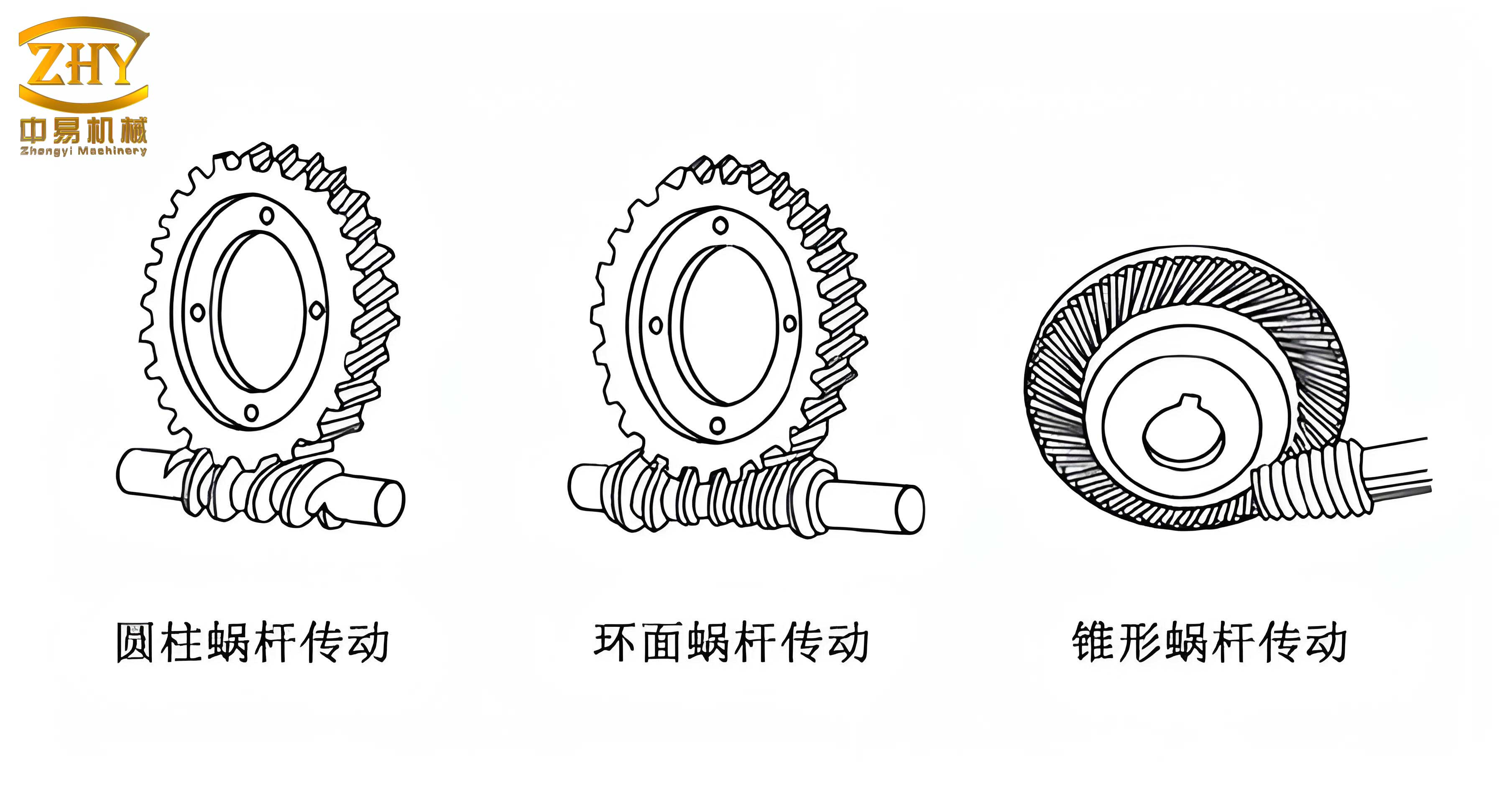
In the field of mechanical engineering, screw gear mechanisms, commonly referred to as worm and worm gear drives, are ubiquitous for applications requiring high reduction ratios, compact design, and smooth, quiet operation. The fundamental principle involves a threaded screw (the worm) meshing with a toothed wheel (the worm gear), where motion and power are transferred between non-intersecting, perpendicular shafts. A typical configuration is shown below.
Despite their advantages, screw gear drives have a characteristic vulnerability: significant sliding contact at the meshing interface. This sliding generates considerable frictional heat. While designs often employ bronze for the worm gear to aid heat dissipation, inadequate operational conditions or poor maintenance can lead to excessive temperatures, lubrication breakdown, and ultimately, catastrophic failure modes like scoring and seizure. This analysis delves into a less common but critical failure in a heavy-duty lifting mechanism: the bending deformation of the worm shaft following a seizure event. We will systematically investigate the structure, materials, forces, stability, and transmission kinematics to pinpoint the root cause and propose corrective measures for future screw gear lifting system designs.
Case Study: Configuration and Structure of the Failed Lifting Mechanism
The subject of this investigation is a large-capacity lifting platform designed for vertical transport. The core actuation system employs three identical SWL-25 type screw gear units arranged linearly on a support structure. The screw gears are fundamentally screw jacks, where the rotating worm drives the worm gear, which is fixed within a housing. The worm shaft itself is prevented from rotating; instead, its axial movement provides the lifting force. In this specific assembly, the worm shafts are connected at their lower ends to a lifting platform (or “carriage”). At their upper ends, they engage with the worm gearboxes. A centrally located drive motor transmits power to all three gearboxes via shafts and universal joints to ensure synchronized operation. The carriage is guided by vertical rails with opposing guide wheels to restrain lateral movement.
During operation, the motor drives the worm gears within the three boxes. Since the worm gears rotate but are axially fixed, the engaged worm shafts are forced to translate vertically, raising or lowering the carriage. The mechanism’s duty cycle involves lifting a fully loaded container from a lower level to a fermentation chamber and subsequently lowering it after processing.
The initial operation was satisfactory. However, over time, all three worm shafts exhibited varying degrees of bending deformation, with one shaft failing most severely. The primary observed symptoms on the disassembled units included darkened, aerated, and diminished lubricating grease within the gearboxes, along with signs of seizure and galling on the worm gear teeth. The carriage structure remained intact but was found misaligned relative to its guide rails.
Material Analysis of the Worm Shafts
A fundamental step in any failure analysis is verifying the material conformance. Samples were taken from all three deformed screw gear worm shafts for spectroscopic chemical analysis. The results are summarized in the table below.
| Element | Worm Shaft 2, Sample 1 | Worm Shaft 2, Sample 2 | Worm Shaft 1 | Worm Shaft 3 |
|---|---|---|---|---|
| C | 0.23% | 0.23% | 0.21% | 0.23% |
| Si | 0.21% | 0.22% | 0.21% | 0.21% |
| Mn | 0.55% | 0.55% | 0.55% | 0.54% |
| P | 0.026% | 0.028% | 0.026% | 0.026% |
| S | 0.010% | 0.011% | 0.008% | 0.009% |
The composition aligns with Grade 25 (or C25) low-carbon steel according to standards like ASTM A29 or equivalent. While this material offers good ductility and toughness, its selection for a heavily loaded, wear-prone component like a screw gear worm shaft is suboptimal. Common design practice for power-transmitting shafts subject to significant stresses and surface wear calls for medium-carbon steels (e.g., AISI 1045, ~0.45% C) or alloy steels (e.g., 4140), which can be heat-treated to achieve higher surface hardness, better wear resistance, and greater strength. The use of a softer, low-carbon steel likely contributed to increased susceptibility to adhesive wear (galling) at the screw gear mesh, especially under poor lubrication conditions.
Static Force Analysis and Shaft Stress
To assess the worm shafts’ adequacy under normal tensile loads, a static force analysis was performed for the worst-case lifting scenario. The system is statically indeterminate because the three screw gear worm shafts share the load elastically. The following parameters were used:
- Carriage Weight, \( Q_c = 29.4 \text{ kN} \)
- Fully Loaded Container Weight, \( Q_l = 186.2 \text{ kN} \)
- Worm Shaft Minor Diameter, \( d = 70 \text{ mm} \)
- Distance between outer screw gears, \( s = 4900 \text{ mm} \)
- Container Width, \( w_c = 4320 \text{ mm} \)
The total load \( Q = Q_c + Q_l = 215.6 \text{ kN} \). Assuming the container load is uniformly distributed, its resultant force acts at the container’s mid-width. Taking moments about the carriage’s geometric center allows us to find the effective load position. The system of equations for the forces in the three worm shafts (\(F_1\), \(F_2\), \(F_3\)) is derived from equilibrium and compatibility conditions (equal deflection for a symmetric carriage under asymmetric load):
1. Force Equilibrium: $$ F_1 + F_2 + F_3 = Q $$
2. Moment Equilibrium: $$ F_2 \cdot \frac{s}{2} + F_3 \cdot s = Q \cdot L $$ where \(L\) is the lateral distance from the system centerline to the resultant load \(Q\).
3. Compatibility (assuming equal shaft length \(h\) and cross-section \(A\)): $$ \frac{F_2 h}{EA} = \frac{F_1 h}{EA} + \frac{F_3 h}{EA} \implies 2F_2 = F_1 + F_3 $$
Solving this system yields the forces carried by each screw gear worm shaft during lifting. The outermost shaft under the load carries the highest force.
| Worm Shaft | Calculated Tensile Force (kN) | Calculated Tensile Stress, \(\sigma_t\) (MPa) |
|---|---|---|
| Shaft 1 (Unloaded Side) | 25.3 | 6.6 |
| Shaft 2 (Central) | 71.9 | 18.7 |
| Shaft 3 (Loaded Side) | 118.4 | 30.8 |
The tensile stress is calculated using the minor diameter area: $$ \sigma_t = \frac{4F}{\pi d^2} $$
For C25 steel with a typical yield strength \(S_y \approx 275 \text{ MPa}\), and applying a conservative safety factor of \(n=2\), the allowable stress \([\sigma] = S_y / n = 137.5 \text{ MPa}\). The maximum operational tensile stress of 30.8 MPa is well within this limit. Therefore, under normal, steady-state lifting conditions, the screw gear worm shafts are not overstressed in tension.
Stability Analysis: Buckling of the Worm Shaft
The preceding analysis confirms the worm shafts are in tension during normal operation. However, the observed bending deformation points toward a compressive instability failure, known as buckling. This scenario becomes plausible if the rotational motion of the screw gear mesh suddenly stops (e.g., due to seizure), while the massive carriage continues its upward movement by inertia, subjecting the worm shaft to a large axial compressive force.
The worm shaft is a long, slender column. Its lower end is fixed to the carriage via a robust bearing housing. Its upper end is constrained by the engaged worm gear teeth, which allow some rotation but restrict lateral movement—this can be approximated as a pinned (simply-supported) connection for buckling analysis. The effective length factor for this end condition is \(\mu \approx 0.7\).
The slenderness ratio \(\lambda\) determines the buckling mode:
$$ \lambda = \frac{\mu L}{r} $$
where \(L = 5550 \text{ mm}\) is the shaft length, and \(r = d/4 = 17.5 \text{ mm}\) is the radius of gyration for a solid circular cross-section. This yields:
$$ \lambda = \frac{0.7 \times 5550}{17.5} \approx 222 $$
For structural steel, the transition slenderness ratio \(\lambda_{1}\) is typically around 100. Since \(\lambda > \lambda_{1}\), the worm shaft is a “long” column, and Euler’s formula for elastic buckling applies.
The critical Euler buckling stress \(\sigma_{cr}\) and critical force \(P_{cr}\) are:
$$ \sigma_{cr} = \frac{\pi^2 E}{\lambda^2} $$
$$ P_{cr} = A \cdot \sigma_{cr} = \frac{\pi d^2}{4} \cdot \frac{\pi^2 E}{\lambda^2} $$
Assuming Young’s Modulus \(E = 210 \text{ GPa}\) for steel:
$$ \sigma_{cr} = \frac{\pi^2 \times 210 \times 10^3}{222^2} \text{ MPa} \approx 42.1 \text{ MPa} $$
$$ P_{cr} = \frac{\pi (0.07)^2}{4} \times 42.1 \times 10^6 \text{ N} \approx 162.1 \text{ kN} $$
This result is pivotal: the screw gear worm shaft will buckle elastically if subjected to a compressive force exceeding approximately 162 kN.
During a sudden seizure event, the dynamic compressive force can be significantly higher than the static tensile force. Using a dynamic impact factor common in elevator safety analysis (\(K_{dyn} = 3\) to \(5\)), the impulsive compressive force on the most loaded screw gear worm shaft could reach:
$$ P_{dyn} = K_{dyn} \times F_3 \approx (3 \text{ to } 5) \times 118.4 \text{ kN} = 355.2 \text{ to } 592.0 \text{ kN} $$
This dynamic force vastly exceeds the critical buckling load \(P_{cr} \approx 162 \text{ kN}\). Therefore, seizure inevitably leads to catastrophic elastic buckling, explaining the observed bending deformation. The predicted buckling mode shape for a fixed-pinned column matches the observed single-curvature bending of the failed worm shaft.
Kinematic and Thermal Analysis: The Role of Transmission Ratio
The investigation now turns to the root cause of the seizure. The core function of any screw gear system is speed reduction and torque multiplication. The specified SWL-25 unit has a recommended gearbox reduction ratio of \(i_{spec} = 32:1\) to achieve its rated performance parameters, including maximum lifting force and safe thermal limits. However, examination of the installed system revealed an actual reduction ratio of \(i_{act} = 24:1\).
This alteration has profound consequences on the screw gear drive’s kinematics and thermal performance. The motor speed was \(n_{motor} = 1470 \text{ rpm}\).
| Parameter | Specified Design (i=32:1) | As-Installed (i=24:1) | Change |
|---|---|---|---|
| Worm Gear Output Speed | \(n_{gear, spec} = 1470 / 32 \approx 45.9 \text{ rpm}\) | \(n_{gear, act} = 1470 / 24 \approx 61.3 \text{ rpm}\) | +33.6% |
| Lifting Speed | \(v_{spec}\) (Proportional to \(n_{gear, spec}\)) | \(v_{act} = 1.336 \times v_{spec}\) | +33.6% |
The increased speed directly escalates the sliding velocity \(v_s\) at the screw gear mesh interface. For a worm with lead \(p_z\) and pitch diameter \(d_{w}\), the sliding velocity is approximated by:
$$ v_s \approx \frac{\pi d_{w} n_{gear}}{60 \times \cos(\gamma)} $$
where \(\gamma\) is the worm lead angle. Therefore, \(v_s\) is linearly proportional to the worm gear speed \(n_{gear}\).
The frictional power loss \(P_{loss}\) and consequent heat generation \(Q_{heat}\) in the screw gear mesh are strongly correlated to the sliding velocity, normal load, and coefficient of friction \(\mu\):
$$ P_{loss} \propto \mu \cdot F_n \cdot v_s $$
$$ Q_{heat} = f(P_{loss}) $$
A 33.6% increase in \(n_{gear}\) (and thus \(v_s\)) leads to a substantial increase in frictional heat generation if all other factors remain constant. Excessive heat causes the lubricant temperature to rise, degrading its viscosity and film-forming ability. This triggers a vicious cycle: poorer lubrication increases the coefficient of friction \(\mu\), which further increases heat generation \(Q_{heat}\), leading to lubricant breakdown, increased wear, and eventually, adhesive seizure of the screw gear pair. The observed state of the lubricant (darkened, aerated, depleted) is a classic symptom of thermal overload and oxidative degradation.
The mismatch in reduction ratio is therefore the primary initiating factor. The screw gear system was forced to operate at a significantly higher speed than its thermal design intended, creating a high risk of overheating and seizure. Once seizure occurred, the inertial forces from the moving carriage induced compressive loads on the slender screw gear worm shafts that far exceeded their buckling strength, causing permanent bending deformation.
Comprehensive Failure Sequence and Design Recommendations
The failure of this screw gear lifting mechanism was not due to a single factor but a chain of interconnected design and maintenance deficiencies. The sequence of events is reconstructed as follows:
- Root Cause (Design Error): Installation of an incorrect, higher-speed reduction gearbox (\(i=24:1\) vs. specified \(i=32:1\)) on the screw gear drive. This increased the operational sliding speed and frictional heat generation beyond the system’s thermal capacity.
- Degradation Mechanism: Chronic overheating degraded the lubricant, reducing its viscosity and lubricity. This led to increased wear and a rising coefficient of friction in the screw gear mesh.
- Maintenance Factor: Likely inadequate monitoring and replenishment of the degraded lubricant, accelerating the thermal runaway condition.
- Triggering Event: Eventual adhesive seizure (galling) of the worm and worm gear teeth, causing sudden rotational locking of the screw gear pair.
- Catastrophic Failure Mode: With the worm shaft rotation halted, the kinetic energy of the massive, upward-moving carriage converted into a high-magnitude dynamic compressive load on the now-stationary screw gear worm shafts.
- Structural Collapse: The dynamic compressive load exceeded the critical Euler buckling load of the long, slender screw gear worm shafts, resulting in elastic instability and permanent bending deformation.
To prevent recurrence in future screw gear lifting mechanism designs, the following recommendations are proposed:
| Aspect | Problem Identified | Recommendation |
|---|---|---|
| Transmission Ratio | Mismatched, higher-speed ratio causing thermal overload. | Strictly adhere to the screw gear manufacturer’s specified speed reduction ratio. Conduct thermal rating verification for the application’s specific duty cycle. |
| Material Selection | Use of low-carbon C25 steel for worm shafts, offering poor wear resistance. | Select medium-carbon (e.g., AISI 1045) or alloy steel (e.g., AISI 4140) for worm shafts. Apply appropriate heat treatment (hardening and tempering) to achieve higher surface hardness and core strength. |
| Lubrication & Maintenance | Degraded lubricant leading to seizure. | Implement a rigorous preventive maintenance schedule. Use high-quality, extreme-pressure (EP) lubricants specified for screw gear applications. Monitor lubricant condition and temperature regularly. |
| Buckling Resistance | Slender shaft design susceptible to buckling post-seizure. | While changing the ratio is primary, consider increasing the worm shaft’s minor diameter \(d\) to lower its slenderness ratio \(\lambda\). This dramatically increases the critical buckling load \(P_{cr} \propto d^4 / L^2\). |
| Protective Systems | No protection against inertial overload after seizure. | Integrate mechanical safety devices such as overspeed sensors, torque limiters, or shear pins designed to disconnect the drive in the event of a blockage, preventing the transfer of excessive compressive loads to the screw gear worm shafts. |
In conclusion, the bending failure of the screw gear worm shafts was a secondary effect. The primary cause was an inappropriate transmission ratio that induced thermal seizure. This case underscores that in screw gear system design, kinematic parameters must be respected not only for force and torque but critically for their thermal implications. Furthermore, the potential for slender actuator members to buckle under fault conditions must be evaluated during the design phase. A holistic approach encompassing correct component selection, adherence to specifications, and proactive maintenance is essential for the reliable operation of screw gear lifting mechanisms.