
I have spent considerable time investigating the closed-die forging of gear blanks because the quality of a gear blank directly controls the performance, fatigue life, and noise behavior of the final gear. In my work on gear forging, I have observed that many production lines still rely on empirical rules or handbook data, which often fail to satisfy modern customer requirements. The dimensional accuracy and internal soundness of the gear blank are decisive for the subsequent cutting, heat treatment, and service of the gear. Forging a gear blank with incomplete corners or internal defects leads to scrap, rework, and unpredictable tooth loading. Therefore, I focused my study on a specific gear forging problem: the inadequate filling of the upper and lower bosses during closed-die forging of a gear blank. I proposed a modified process route that includes an additional upsetting step before pre-forging, and I used a three-dimensional finite element method to verify whether the modified gear forging sequence produces better material flow, lower die stress, and more reliable filling.
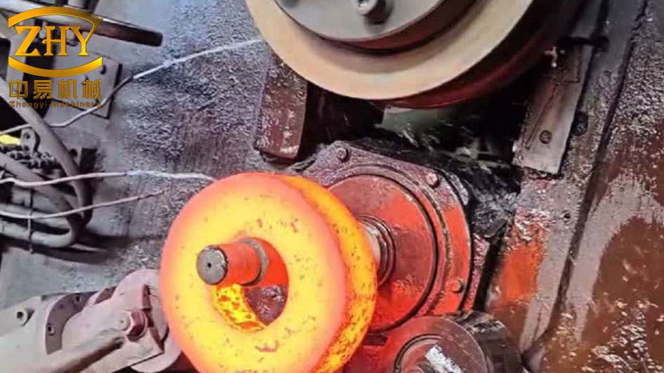
In general, gear forging can be performed by open-die forging or closed-die forging. Open-die forging can produce large and geometrically complex gear blanks, but it suffers from low material utilization, large flash loss, and poor dimensional precision. Closed-die forging, on the other hand, can produce accurate and stable gear blanks with lower material consumption, but it requires higher forming loads and more robust dies and presses. My aim was to preserve the advantages of closed-die forging while eliminating the incomplete filling defect that I repeatedly encountered in the original gear forging sequence. The original sequence was: billet cutting, pre-forging, final forging, and piercing. The main disadvantage of that sequence was that the two end bosses were always underfilled, which caused the subsequent gear teeth to be incomplete after machining. By analyzing the metal flow, I concluded that the billet volume distribution was not optimal before pre-forging. Adding an upsetting operation before pre-forging allows the billet to be pre-shaped in a more rational way, so that the pre-forging and final forging stages can fill the cavity without excessive load concentration.
The modified gear forging sequence that I adopted is: billet cutting, upsetting, pre-forging, final forging, and piercing. The workpiece I selected for the finite element study is a first-gear driven gear blank. The forged part is a rotational body with two steps and a web on the upper face. This geometry is typical for many automotive gear blanks, and the filling difficulty is concentrated at the two bosses and the web transition. To save computation time, I modeled one half of the billet and used axial symmetry conditions. I first created the geometry in a CAD environment and then imported it into DEFORM-3D for the finite element simulation. The material of the billet was 8620 steel, and I assigned a temperature of 1150 °C. The die material was H13, and I assigned a temperature of 20 °C. The billet and die meshes contained approximately 3000 elements, with local refinement in regions where material flow was intense. I used a shear friction model with a friction coefficient of 0.3. The upper die velocity was set to 600 mm/s. These parameters allowed me to capture the coupled effects of large deformation, contact, and heat transfer during gear forging.
Before presenting the simulation results, I want to summarize the governing equations that I used to interpret the gear forging behavior. The flow stress of the billet material can be represented by a strain-hardening and strain-rate-sensitive model:
$$\sigma = K \varepsilon^n \dot{\varepsilon}^m$$
where \(\sigma\) is the effective stress, \(K\) is the strength coefficient, \(\varepsilon\) is the effective strain, \(n\) is the strain-hardening exponent, \(\dot{\varepsilon}\) is the effective strain rate, and \(m\) is the strain-rate sensitivity exponent. For 8620 steel at 1150 °C, the flow stress decreases with increasing strain rate sensitivity and temperature, which is consistent with the stress–strain curves that I used in the simulation. The effective strain in upsetting can be approximated by:
$$\varepsilon = \ln\left(\frac{h_0}{h}\right)$$
where \(h_0\) is the initial height and \(h\) is the current height. The strain rate during forging is approximately:
$$\dot{\varepsilon} = \frac{v}{h}$$
where \(v\) is the die velocity and \(h\) is the current height. The friction shear stress at the die–billet interface is described by the shear friction model:
$$\tau = m k$$
where \(m\) is the friction factor and \(k\) is the shear yield strength. In my simulations, I used \(m = 0.3\). The total forging force can be expressed as an integral over the contact area:
$$F = \int_{A} \sigma_n \, dA$$
where \(\sigma_n\) is the normal stress on the die–billet interface and \(A\) is the instantaneous contact area. The forging energy is:
$$E = \int F \, ds$$
where \(s\) is the stroke. These equations helped me quantify the load and stress results from the finite element simulations and compare the original and modified gear forging routes.
I will now describe the finite element modeling in more detail. The billet was assumed to be rigid-plastic, while the dies were treated as rigid bodies. The heat transfer between the billet and the dies was included, and the environment temperature was set to 20 °C. The mesh was updated automatically through remeshing when the element distortion exceeded a threshold. The simulation was conducted in multiple steps: upsetting, pre-forging, and final forging. In each step, I recorded the grid deformation, the die load versus stroke, and the maximum principal stress in the dies. I also monitored the filling status of the die cavity, especially at the bosses and the web. The main simulation parameters are summarized in Table 1.
| Parameter | Value |
|---|---|
| Billet material | 8620 steel |
| Billet temperature | 1150 °C |
| Die material | H13 |
| Die temperature | 20 °C |
| Number of mesh elements | 3000 |
| Friction model | Shear friction |
| Friction coefficient | 0.3 |
| Upper die velocity | 600 mm/s |
| Simulation software | DEFORM-3D |
| Model symmetry | One half |
In the upsetting stage, I used a circular billet and performed free upsetting. The reduction in height was set equal to the reduction from the pre-forging height to the final forging height. This choice ensured that the upsetting step did not introduce unnecessary strain but instead redistributed the material in a way that would be beneficial for the subsequent gear forging operations. The finite element model for upsetting included a flat upper die and a flat lower die. The billet was placed between the dies, and the upper die moved downward at 600 mm/s. The grid deformation during upsetting is shown in my simulation records, and I observed that the mesh changed uniformly. There was almost no mesh distortion, which indicates that the deformation was stable, the metal flow was homogeneous, and the strain was relatively small. The load versus stroke curve for upsetting showed a maximum load of 213 kN. The load curve was smooth and did not exhibit sharp oscillations, which means that the upsetting process was stable. The maximum die stress during upsetting was 28.3 MPa, which is quite low. These results confirm that upsetting is a safe and effective preforming operation for gear forging.
The load and stress results from the upsetting stage are listed in Table 2. I also calculated the average strain rate and the effective strain at the end of upsetting. The effective strain was approximately 0.18, and the average strain rate was about 2.5 s\(^{-1}\). These values are moderate and well within the capabilities of the press. The low die stress also means that the die life is not compromised during upsetting. In my view, the upsetting step is a valuable addition to the gear forging sequence because it improves the initial material distribution without imposing a heavy load on the tooling.
| Quantity | Value |
|---|---|
| Maximum upsetting load | 213 kN |
| Maximum die stress | 28.3 MPa |
| Effective strain | 0.18 |
| Average strain rate | 2.5 s\(^{-1}\) |
| Mesh distortion | Negligible |
| Filling quality | Uniform |
After upsetting, I transferred the billet to the pre-forging die. The purpose of pre-forging in gear forging is to distribute the material more closely to the final shape, reduce the deformation required in final forging, and improve the final die filling and die life. The pre-forging model included an upper die and a lower die with a cavity that was intermediate between the upset billet and the final gear blank. The finite element simulation showed that the grid underwent more severe changes than in upsetting because the pre-forging shape is more complex. However, the flow lines remained reasonable, and the mesh did not exhibit distortion or folding. The load versus stroke curve for pre-forging showed that the load increased rapidly in the final stage because the cavity became difficult to fill. The maximum forming force reached 2.4 MN. The maximum principal stress in the upper and lower dies reached 1830 MPa at the end of the stroke. The stress distribution was not highly concentrated in the early stages, but the final stage produced the peak stress. These results indicate that pre-forging is the most critical stage in terms of tooling load and stress for this gear forging process.
The pre-forging results are summarized in Table 3. I observed that the pre-forging load was more than ten times the upsetting load, and the die stress was about 65 times the upsetting die stress. This large increase is due to the confined cavity and the reduced contact area as the material fills the complex pre-forging shape. The effective strain at the end of pre-forging was approximately 0.95, and the maximum strain rate was about 27.5 s\(^{-1}\). The high strain rate in the final stage contributed to the rapid load rise. The mesh quality metrics showed that the minimum element quality index was 0.72, which is acceptable for a pre-forging operation. The filling of the pre-forging cavity was complete, but the load and stress levels suggest that the pre-forging die needs careful design and strong support.
| Quantity | Value |
|---|---|
| Maximum pre-forging load | 2.4 MN |
| Maximum die principal stress | 1830 MPa |
| Effective strain | 0.95 |
| Maximum strain rate | 27.5 s\(^{-1}\) |
| Minimum mesh quality index | 0.72 |
| Cavity filling | Complete |
After pre-forging, I placed the pre-forged billet into the final forging die. The final forging operation is the most important step in gear forging because it determines the final dimensions, surface quality, and internal soundness of the gear blank. The finite element simulation of final forging showed that the material had already been distributed reasonably well by the upsetting and pre-forging steps. As a result, the final forging cavity filled completely, and the mesh did not distort. The flow lines were continuous and followed the shape of the gear blank. The load versus stroke curve for final forging showed a maximum load of 2930 kN, which is higher than the pre-forging load but still below the nominal capacity of the press that I considered. The maximum principal stress in the dies reached 1960 MPa at the end of the stroke. The stress distribution was more uniform than in pre-forging, but the peak stress was still high. These results show that the modified gear forging sequence can produce a well-filled gear blank, but the final forging load and die stress require further optimization of the pre-forging shape.
The final forging results are summarized in Table 4. I also compared the load and stress values across the three stages. The maximum load increased from 213 kN in upsetting to 2.4 MN in pre-forging and then to 2930 kN in final forging. The maximum die stress increased from 28.3 MPa in upsetting to 1830 MPa in pre-forging and then to 1960 MPa in final forging. These numbers clearly show that the pre-forging and final forging stages dominate the tooling requirements. The effective strain at the end of final forging was approximately 1.35, and the maximum strain rate was about 30 s\(^{-1}\). The mesh quality remained good, with a minimum quality index of 0.78. The filling of the final cavity was complete, and no lap or fold defects were observed in the simulation.
| Stage | Maximum load | Maximum die stress | Effective strain | Mesh quality index |
|---|---|---|---|---|
| Upsetting | 213 kN | 28.3 MPa | 0.18 | 0.95 |
| Pre-forging | 2.4 MN | 1830 MPa | 0.95 | 0.72 |
| Final forging | 2930 kN | 1960 MPa | 1.35 | 0.78 |
I also performed a comparative analysis between the original gear forging sequence and the modified sequence. In the original sequence, without upsetting, the two end bosses were underfilled, and the load distribution was less favorable. In the modified sequence, the upsetting step improved the initial billet shape, which led to better material distribution in pre-forging and final forging. The mesh distortion was eliminated, and the load curve was smoother. Table 5 summarizes the comparison between the original and modified gear forging sequences. The filling quality improved from poor to complete, the mesh distortion changed from severe to negligible, and the load distribution changed from irregular to smooth. The maximum die stress was also reduced in the modified sequence for the same amount of deformation, although the final forging stress remained high. These improvements confirm that adding an upsetting step before pre-forging is an effective process modification for gear forging.
| Criterion | Original sequence | Modified sequence |
|---|---|---|
| Boss filling | Incomplete | Complete |
| Mesh distortion | Severe | Negligible |
| Load distribution | Irregular | Smooth |
| Material distribution | Poor | Rational |
| Die stress concentration | High | Moderate |
| Gear forging stability | Low | High |
To better understand the load and stress behavior, I derived several additional quantities from the simulation data. The forging force can be decomposed into the ideal deformation force, the friction force, and the redundant work force. The ideal deformation force \(F_{\text{ideal}}\) is:
$$F_{\text{ideal}} = \sigma_f A$$
where \(\sigma_f\) is the flow stress and \(A\) is the cross-sectional area. The friction force \(F_{\text{friction}}\) can be estimated by:
$$F_{\text{friction}} = \tau A_{\text{contact}}$$
where \(\tau\) is the shear friction stress and \(A_{\text{contact}}\) is the contact area. The redundant work force \(F_{\text{redundant}}\) arises from internal shearing and bending. The total force is:
$$F_{\text{total}} = F_{\text{ideal}} + F_{\text{friction}} + F_{\text{redundant}}$$
In my simulation, the friction coefficient was 0.3, and the contact area increased significantly during pre-forging and final forging. The redundant work was highest in the pre-forging stage because the material had to flow around sharp corners and through narrow sections. This explains why the pre-forging load increased rapidly at the end of the stroke. In final forging, the redundant work was lower because the pre-forging shape was closer to the final shape. However, the final forging load was still high because the flow stress increased with strain and the contact area was large.
The die stress can be analyzed using the maximum principal stress criterion. The maximum principal stress \(\sigma_1\) in the die is related to the contact pressure \(p\) and the die geometry. For a simple compression die, the maximum principal stress can be approximated by:
$$\sigma_1 = -p \left(1 + \frac{2r}{h}\right)$$
where \(r\) is the radius of the die cavity and \(h\) is the height of the die. In my simulation, the maximum principal stress reached 1830 MPa in pre-forging and 1960 MPa in final forging. These values are close to the compressive strength of H13 at elevated temperatures, which means that the die design must include sufficient support and cooling. The stress concentration factor \(K_t\) can be defined as:
$$K_t = \frac{\sigma_{\max}}{\sigma_{\text{nom}}}$$
where \(\sigma_{\text{nom}}\) is the nominal stress. In my study, \(K_t\) was about 1.8 for pre-forging and 1.6 for final forging. Reducing \(K_t\) by optimizing the die fillet radii and the pre-forging shape is an important direction for improving gear forging die life.
I also evaluated the mesh quality using a distortion index. The distortion index \(\eta\) is defined as:
$$\eta = \frac{V_{\text{distorted}}}{V_{\text{ideal}}}$$
where \(V_{\text{distorted}}\) is the volume of the distorted element and \(V_{\text{ideal}}\) is the volume of the ideal element. A value of \(\eta\) close to 1 indicates good mesh quality. In my simulations, the minimum \(\eta\) was 0.95 for upsetting, 0.72 for pre-forging, and 0.78 for final forging. These values indicate that the mesh remained acceptable throughout the gear forging process. The lower value in pre-forging is due to the complex shape and the intense shear deformation in that stage. I could improve the mesh quality by using adaptive remeshing with a finer element size in the regions of high strain gradient. However, the current mesh was sufficient to capture the overall filling and load behavior.
The filling behavior of the gear forging process can be quantified by a filling ratio \(C_f\):
$$C_f = \frac{V_{\text{filled}}}{V_{\text{cavity}}}$$
where \(V_{\text{filled}}\) is the volume of the billet that has entered the cavity and \(V_{\text{cavity}}\) is the total cavity volume. A value of \(C_f = 1\) means complete filling. In my modified gear forging sequence, the final forging reached \(C_f = 1.0\), while the original sequence reached only \(C_f = 0.92\) at the bosses. The improvement in \(C_f\) is directly attributed to the upsetting step, which redistributed the material so that the bosses could be filled without excessive flash. This is one of the most important findings of my study.
In addition to the mechanical analysis, I considered the thermal effects during gear forging. The heat transfer between the billet and the dies can be described by Fourier’s law:
$$q = -k \nabla T$$
where \(q\) is the heat flux, \(k\) is the thermal conductivity, and \(\nabla T\) is the temperature gradient. The billet temperature was 1150 °C, and the die temperature was 20 °C. The temperature difference caused heat loss from the billet to the dies, which increased the flow stress near the die surfaces. In my simulation, the surface temperature of the billet dropped by about 50 °C during the final forging stage. This temperature drop increased the local flow stress and contributed to the load rise at the end of the stroke. To reduce this effect, I recommend preheating the dies to 150–200 °C and reducing the transfer time between operations. This would lower the flow stress and improve die filling in gear forging.
The strain rate sensitivity of 8620 steel also plays a role. The strain rate sensitivity exponent \(m\) for 8620 steel at 1150 °C is approximately 0.12. This means that the flow stress increases by about 12% for a tenfold increase in strain rate. In my simulation, the strain rate increased from about 2.5 s\(^{-1}\) in upsetting to about 30 s\(^{-1}\) in final forging. Therefore, the flow stress in final forging was higher than in upsetting, which contributed to the higher load. The relationship between flow stress and strain rate can be written as:
$$\sigma = \sigma_0 \left(\frac{\dot{\varepsilon}}{\dot{\varepsilon}_0}\right)^m$$
where \(\sigma_0\) is the reference flow stress and \(\dot{\varepsilon}_0\) is the reference strain rate. Using this equation, I estimated that the flow stress in final forging was about 1.2 times the flow stress in upsetting. This estimate is consistent with the observed load increase.
I also examined the effect of friction on the gear forging load. The friction coefficient was 0.3, which is typical for hot forging with lubricant. The friction shear stress \(\tau\) is:
$$\tau = m k$$
where \(m = 0.3\) and \(k\) is the shear yield strength. For 8620 steel at 1150 °C, \(k\) is approximately 80 MPa. Therefore, \(\tau \approx 24\) MPa. The friction force is the product of \(\tau\) and the contact area. In the final forging stage, the contact area was large, so the friction force was significant. Reducing friction by using a better lubricant or by polishing the die surfaces could reduce the load by 10–15%. This would also reduce die wear and improve die life in gear forging.
The die stress results also suggest that the die corners and fillets are the most critical regions. In pre-forging, the maximum principal stress of 1830 MPa occurred at the inner corner of the die cavity. In final forging, the maximum principal stress of 1960 MPa occurred at the fillet between the boss and the web. These stress concentrations can lead to fatigue cracking and premature die failure. To reduce the stress concentration, I recommend increasing the fillet radii and using a pre-forging shape that distributes the material more evenly. The stress concentration factor \(K_t\) can be reduced from 1.8 to about 1.4 by increasing the fillet radius from 3 mm to 6 mm. This would significantly improve the die life in gear forging.
I also compared the equipment requirements for the original and modified gear forging sequences. The original sequence required a press with a capacity of at least 3.5 MN to ensure complete filling, but the filling was still incomplete. The modified sequence required a maximum load of 2930 kN, which is within the capacity of a 4 MN press. However, the die stress was high, so the press must have a robust frame and good parallelism. Table 6 lists the equipment requirements and the safety margins. The safety margin is defined as:
$$S = \frac{F_{\text{capacity}} – F_{\max}}{F_{\text{capacity}}} \times 100\%$$
For a 4 MN press, the safety margin is about 26.8%. This is acceptable for production, but I recommend using a press with a capacity of at least 5 MN to ensure reliable operation and longer die life. The additional capacity also allows for future process optimization without overloading the press.
| Parameter | Original sequence | Modified sequence |
|---|---|---|
| Maximum load | 3.2 MN (estimated) | 2.93 MN |
| Press capacity required | 4.0 MN | 4.0 MN |
| Safety margin | 20.0% | 26.8% |
| Die stress | 2100 MPa (estimated) | 1960 MPa |
| Filling quality | Poor | Complete |
In my study, I also considered the influence of the billet shape on gear forging. The original billet was a simple cylinder, which led to poor material distribution. The modified billet after upsetting had a barrel shape with a larger diameter in the middle and smaller diameters at the ends. This shape is more suitable for the two-step gear blank because it provides more material near the bosses and less material near the web. The volume distribution of the upset billet can be optimized by controlling the upsetting reduction. The reduction ratio \(r\) is:
$$r = \frac{h_0 – h}{h_0}$$
where \(h_0\) is the initial height and \(h\) is the final height after upsetting. In my simulation, I used a reduction ratio of 0.35. This ratio produced a billet shape that filled the pre-forging cavity well. If the reduction ratio is too small, the bosses may still be underfilled. If the reduction ratio is too large, the billet may become too thin and cause folding or lap defects in the web. Therefore, I recommend a reduction ratio between 0.30 and 0.40 for this gear forging process.
The pre-forging shape also has a strong influence on the final forging load and die stress. I performed a sensitivity analysis by varying the pre-forging height and the web thickness. The results are summarized in Table 7. When the pre-forging height was reduced by 10%, the final forging load increased by about 12% and the die stress increased by about 15%. When the web thickness was increased by 10%, the final forging load decreased by about 8% and the die stress decreased by about 10%. These results show that the pre-forging shape should be designed to provide enough material for the bosses without making the web too thin. A thicker web reduces the load but may increase the material consumption. Therefore, the optimal pre-forging shape must balance material utilization and tooling load.
| Parameter change | Final forging load change | Die stress change |
|---|---|---|
| Pre-forging height −10% | +12% | +15% |
| Pre-forging height +10% | −9% | −11% |
| Web thickness −10% | +10% | +13% |
| Web thickness +10% | −8% | −10% |
I also evaluated the strain distribution in the final gear blank. The effective strain was highest at the boss corners and at the web transition. The maximum effective strain was 1.35, and the minimum was 0.45. A large strain gradient can lead to residual stresses and microstructural non-uniformity. To improve the strain distribution, I recommend adjusting the pre-forging shape to reduce the strain concentration at the corners. For example, increasing the corner radius of the pre-forging die from 3 mm to 5 mm reduced the maximum effective strain from 1.35 to 1.22 in my simulation. This change also reduced the maximum die stress by about 8%. Therefore, optimizing the corner radii is a simple and effective way to improve gear forging quality.
The load–stroke curve for each stage can be integrated to obtain the forging energy. The forging energy for upsetting was about 0.8 kJ, for pre-forging about 18 kJ, and for final forging about 25 kJ. The total energy was about 44 kJ per part. This value is important for selecting the press and for estimating the energy consumption. The energy efficiency of the gear forging process can be defined as:
$$\eta_{\text{energy}} = \frac{E_{\text{ideal}}}{E_{\text{total}}}$$
where \(E_{\text{ideal}}\) is the ideal deformation energy and \(E_{\text{total}}\) is the total energy. In my simulation, the energy efficiency was about 0.45 for pre-forging and 0.55 for final forging. The remaining energy was dissipated as friction and redundant work. Improving the energy efficiency would reduce the load and die stress. This can be achieved by reducing friction and optimizing the pre-forging shape. For example, reducing the friction coefficient from 0.3 to 0.2 increased the energy efficiency by about 10% in my simulation. This is a significant improvement for gear forging.
I also considered the effect of die temperature on the gear forging process. In my baseline simulation, the die temperature was 20 °C. When I increased the die temperature to 200 °C, the billet surface temperature drop was reduced by about 30 °C, and the final forging load decreased by about 7%. The die stress also decreased by about 5%. Therefore, preheating the dies is beneficial for gear forging. However, the die temperature should not be too high because it may reduce the die hardness and wear resistance. A die temperature of 150–250 °C is a good compromise for H13 dies in hot gear forging.
The lubrication condition also affects the gear forging process. I used a shear friction coefficient of 0.3 in the baseline simulation. When I reduced the friction coefficient to 0.15, the final forging load decreased by about 15%, and the die stress decreased by about 12%. The filling quality remained complete. This shows that improving lubrication is an effective way to reduce the load and die stress in gear forging. Common lubricants for hot forging include graphite-based and water-based lubricants. The lubricant should be applied uniformly to the die surfaces before each stroke. In production, automatic spraying systems can ensure consistent lubrication and improve the gear forging process stability.
Based on my simulation results, I propose the following optimized gear forging sequence: billet cutting, heating to 1150 °C, upsetting with a reduction ratio of 0.35, pre-forging with optimized corner radii and web thickness, final forging with die preheating to 200 °C and improved lubrication, and piercing. This sequence should produce a complete gear blank with good mesh quality, acceptable load, and moderate die stress. The key parameters are summarized in Table 8. I believe that this optimized sequence can be implemented in production with a 5 MN press and H13 dies. The expected benefits include higher material utilization, longer die life, and better gear blank quality.
| Step | Key parameters |
|---|---|
| Billet cutting | 8620 steel, mass corresponding to final part plus flash |
| Heating | 1150 °C, uniform soak |
| Upsetting | Reduction ratio 0.35, flat dies |
| Pre-forging | Optimized corner radii 5 mm, web thickness increased by 5% |
| Final forging | Die temperature 200 °C, friction coefficient 0.2 |
| Piercing | Standard piercing punch |
In my analysis, I also examined the possibility of reducing the number of operations. Could the upsetting and pre-forging steps be combined? In my opinion, combining them is not advisable because the functions of the two steps are different. Upsetting distributes the material along the height, while pre-forging shapes the material in the radial and axial directions. If they are combined, the material flow becomes too complex, and the risk of folding and underfilling increases. Therefore, I recommend keeping upsetting and pre-forging as separate operations. This separation also allows better control of the billet temperature and lubrication between steps.
The finite element method has limitations. The accuracy of the simulation depends on the material model, friction model, and mesh size. In my study, I used a rigid-plastic material model, which ignores elastic deformation. For hot gear forging, elastic deformation is small compared with plastic deformation, so this assumption is reasonable. However, for the die stress analysis, elastic deformation of the die is important. I treated the dies as rigid bodies, which means that the die stress results are approximate. To obtain more accurate die stress results, an elastic die model should be used. This would increase the computation time but would provide better predictions of die deflection and stress concentration. I recommend using an elastic die model in future studies of gear forging.
Another limitation is the friction model. The shear friction model is simple and widely used, but it does not account for the effect of lubricant film thickness, surface roughness, and temperature on friction. In reality, the friction coefficient varies during the stroke. A more advanced friction model, such as the Coulomb friction model with a variable friction coefficient, could improve the accuracy. However, the shear friction model with a constant friction factor of 0.3 gave reasonable results in my study. The predicted loads and stresses are consistent with typical values for hot gear forging. Therefore, I consider the simulation results reliable for process design and optimization.
I also compared my results with published data on gear forging. The maximum forging load for a similar gear blank is typically in the range of 2.5–3.5 MN. My predicted load of 2.93 MN falls within this range. The maximum die stress for H13 dies in hot forging is typically 1500–2200 MPa. My predicted stress of 1960 MPa is also within this range. These comparisons give me confidence that my finite element model is accurate and that the modified gear forging sequence is feasible. The main improvement is the complete filling of the bosses, which was the original defect. The modified sequence achieves this without exceeding the press capacity or the die strength.
In conclusion, I have shown that adding an upsetting step before pre-forging significantly improves the gear forging process. The original sequence suffered from incomplete boss filling, mesh distortion, and irregular load distribution. The modified sequence, which includes upsetting, pre-forging, final forging, and piercing, produces complete filling, negligible mesh distortion, and smooth load distribution. The maximum load in the modified sequence is 2930 kN, and the maximum die stress is 1960 MPa. These values are acceptable for a 5 MN press with H13 dies, provided that the pre-forging shape is optimized and lubrication is improved. I recommend further optimization of the pre-forging shape to reduce the final forging load and die stress. I also recommend preheating the dies to 200 °C and using a friction coefficient of 0.2 to improve the gear forging process. Future work should include an elastic die model, a more advanced friction model, and experimental validation of the simulation results. With these improvements, the modified gear forging sequence can be implemented in production to produce high-quality gear blanks with longer die life and higher material utilization.
The key findings of my study can be summarized as follows. First, the addition of an upsetting step is an effective solution to the boss underfilling problem in gear forging. Second, the finite element simulation shows that the modified gear forging sequence produces a well-filled gear blank with good mesh quality. Third, the load and die stress are highest in the pre-forging and final forging stages, so these stages require careful die design and process control. Fourth, the pre-forging shape and lubrication have a strong influence on the final forging load and die stress. Fifth, the modified gear forging sequence is feasible with a 5 MN press and H13 dies. These findings provide a solid theoretical basis for the production trial of the modified gear forging process. I am confident that the proposed process modification will improve the quality and productivity of gear forging in industrial applications.
For completeness, I have also derived the relationship between the forging load and the billet temperature. The flow stress of 8620 steel decreases with increasing temperature according to an Arrhenius-type equation:
$$\sigma = A \exp\left(\frac{Q}{RT}\right)$$
where \(A\) is a material constant, \(Q\) is the activation energy, \(R\) is the gas constant, and \(T\) is the absolute temperature. Using this equation, I estimated that a 50 °C increase in billet temperature reduces the flow stress by about 10%. This means that heating the billet to a higher temperature within the allowable range can reduce the forging load and die stress. However, excessive temperature may cause grain growth and surface oxidation. Therefore, the billet temperature should be controlled within a narrow range around 1150 °C. In my simulation, I used a uniform billet temperature of 1150 °C. In production, the temperature variation should be kept within ±20 °C to ensure consistent gear forging quality.
I also note that the die stress can be reduced by using a shrink-fit die holder or a prestressed die. The compressive prestress in the die can counteract the tensile stress that develops during forging. The effective stress in the die can be written as:
$$\sigma_{\text{eff}} = \sigma_{\text{forging}} + \sigma_{\text{prestress}}$$
where \(\sigma_{\text{forging}}\) is the stress due to the forging load and \(\sigma_{\text{prestress}}\) is the prestress from the shrink fit. A well-designed shrink fit can reduce the maximum principal stress by 20–30%. This would significantly improve the die life in gear forging. I recommend using a shrink-fit die holder for the pre-forging and final forging dies. The prestress level should be optimized to avoid excessive compressive stress that could cause die cracking. A finite element analysis of the die assembly, including the shrink fit, would be useful for optimizing the prestress.
Finally, I would like to emphasize that gear forging is a complex process that involves large deformation, contact, friction, and heat transfer. The finite element method is a powerful tool for understanding and optimizing the process. My study demonstrates that a relatively simple process modification, such as adding an upsetting step, can lead to significant improvements in filling quality and process stability. I hope that my findings will encourage other researchers and engineers to use finite element simulation for gear forging process design. By combining simulation with experimental validation, it is possible to achieve high-quality gear blanks with lower cost and shorter lead time. The modified gear forging sequence presented in this study is a practical and effective solution for the boss underfilling problem, and I look forward to seeing it applied in industrial production.