
I see the gear as one of the most important load-bearing and motion-transfer elements in the electric drive transmission system of a new energy vehicle. In my view, the entire performance chain of a new energy vehicle is strongly influenced by the quality of gear cutting, gear finishing, and gear surface creation. As electric drive systems move toward higher motor speeds, greater power density, lower noise, and longer fatigue life, I cannot treat gear cutting as a simple shape-generation operation. Instead, I must treat gear cutting as a coupled system problem that connects tooth flank generation, process mechanics, machine tool accuracy, tool wear, surface integrity, and final service performance. The central argument I develop here is that high-efficiency precision machining of new energy vehicle gears must be understood through a three-level mapping: service performance, tooth surface creation performance, and process system parameters. This mapping determines how I should design gear cutting processes, select gear cutting tools, control gear cutting machines, and optimize gear cutting parameters.
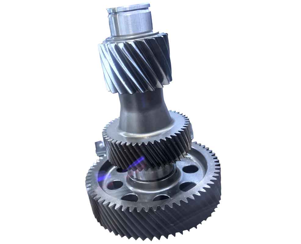
Demand and performance targets. I begin with the demand side because the required performance of new energy vehicle gears is changing faster than many conventional gear cutting workflows can adapt. A typical electric drive transmission often uses a single-speed reducer with two gear pairs and three main shaft components: the motor input shaft gear, the intermediate shaft gear, and the output gear. The intermediate shaft gear may be a double gear with two toothed sections. The motor speed has reached approximately 25,000 r/min and is moving toward 30,000 r/min. Because electric motors are much quieter than internal combustion engines, the noise, vibration, and harshness behavior of the reducer becomes more prominent. Gear whine, ghost frequency screaming, regenerative braking impact, and fatigue failure become key concerns. Therefore, I must achieve high geometric accuracy, complex tooth flank modification, controlled surface topography, favorable residual stress, and stable batch consistency. These targets directly affect gear cutting strategy, gear cutting tool life, and gear cutting machine design.
| Requirement | Physical meaning | Consequence for gear cutting |
|---|---|---|
| High speed | High pitch line velocity and high meshing frequency | Reduce profile error, lead error, waviness, and dynamic excitation |
| Low noise | Low gear whine and ghost frequency noise | Control tooth flank texture, roughness, waviness, and modification |
| Fatigue resistance | High contact and bending fatigue life | Generate compressive residual stress and avoid grinding burn |
| Power density | Higher torque per unit volume | Improve load capacity through topology modification and surface integrity |
| Batch consistency | Stable quality in mass production | Monitor tool wear, thermal error, and process system dynamics |
| Manufacturing efficiency | Short cycle time and low cost | Optimize gear cutting parameters, tool speed, feed, and machine architecture |
For me, the most difficult part is that shape accuracy alone is not sufficient. A gear can pass conventional geometric inspection and still produce unacceptable noise or fatigue failure. This is why I emphasize that gear cutting must be designed not only for nominal involute geometry but also for surface integrity. The tooth surface must be modified in a controlled way, the surface texture must be oriented and distributed appropriately, the roughness must be kept within a functional range, the waviness must avoid strong spectral peaks, and the residual stress must remain compressive. These requirements make gear cutting a multi-objective problem rather than a single-objective accuracy problem.
Process routes and gear cutting selection. The general manufacturing route for new energy vehicle gears is soft roughing, heat treatment, and hard finishing. Because heat treatment distortion cannot be predicted with perfect accuracy, hard finishing remains the key step that guarantees final service performance. Although many finishing methods exist, including magnetic abrasive polishing, abrasive flow machining, and laser surface texturing, mass automotive production still relies primarily on mature high-efficiency precision gear cutting processes. Among these, continuous generating grinding with a worm grinding wheel and internal meshing power honing are the two most important processes. I treat both as gear cutting processes in the broad sense because they remove material through defined cutting edges on an abrasive tool while maintaining a conjugate meshing relationship between the tool and the workpiece.
The kinematic principle is that the abrasive tool and the gear maintain a crossed-axis helical gear meshing relation. Material removal occurs at contact points where the relative sliding velocity and the common normal satisfy the conjugate condition. I can express the general condition as
$$ \mathbf{v}^{(12)} \cdot \mathbf{n}^{(12)} = 0 $$
where v(12) is the relative velocity between tool and workpiece at the contact point, and n(12) is the common normal. For worm grinding, a more detailed meshing equation can be written as
$$
\begin{aligned}
f_g ={}& r_b \cot\beta_b \sin\Sigma_g \cos\phi_g
+ r_b \cot\beta_b \cos\Sigma_g \sin\phi_g \\
&+ r_b \cot\beta_b \sin\Sigma_g \sin\phi_g
– r_b \cot\beta_b \cos\Sigma_g \cos\phi_g \\
&+ p \cos\Sigma_g \sin\phi_g – p \sin\Sigma_g \cos\phi_g \\
&+ a \cot\beta_b \cos\Sigma_g \sin\phi_g
– a \cot\beta_b \sin\Sigma_g \cos\phi_g \\
&+ v_f \cot\beta_b \cos\Sigma_g \cos\phi_g
– v_f \cot\beta_b \sin\Sigma_g \sin\phi_g = 0
\end{aligned}
$$
For internal meshing power honing, I express the corresponding meshing equation as
$$
\begin{aligned}
f_h ={}& a p \cos\Sigma_h \sin\phi_h
+ p r_b \cos\Sigma_h \cos\phi_h \\
&- a p \sin\Sigma_h \cos\phi_h
+ p r_b \sin\Sigma_h \sin\phi_h \\
&- p a i_h \cos\Sigma_h \sin\phi_h
+ p a i_h \sin\Sigma_h \cos\phi_h = 0
\end{aligned}
$$
These equations are not merely mathematical formalism. They tell me how the tool axis angle, center distance, workpiece rotation, tool rotation, and axial feed jointly determine the contact trace. If I change any of these variables to obtain a modified tooth flank, I also change the local cutting velocity, the uncut chip geometry, the force distribution, the heat distribution, and the resulting surface integrity. This is why I insist that gear cutting process design must be integrated rather than sequential.
| Feature | Worm grinding wheel gear cutting | Internal meshing power honing gear cutting |
|---|---|---|
| Tool type | Worm-shaped grinding wheel | Internal gear-shaped honing wheel |
| Meshing relation | Crossed-axis worm and gear | Crossed-axis internal gear and external gear |
| Typical cutting speed | Very high, around 80 to 100 m/s and above | Low to moderate, around 10 to 20 m/s |
| Material removal amount | Relatively large, capable of correcting heat treatment distortion | Small, mainly for final accuracy and surface integrity |
| Thermal effect | Significant, risk of burn and tensile residual stress | Low, usually avoids burn |
| Surface texture | Predominantly parallel or controlled traces | Characteristic cross-hatched or herringbone texture |
| Residual stress | Compressive but sensitive to heat accumulation | Usually stronger compressive stress |
| Typical limitation | Ghost frequency risk and thermal damage | Machine tool stiffness, tool diameter, axis angle, and tool breakage |
Cutting velocity and trace formation. I calculate the local cutting velocity because it controls the interaction between the abrasive grit and the tooth flank. For worm grinding, the velocity components are
$$
v_{gd} = 2\pi n_g r_{gw}, \qquad
v_{gs} = 2\pi n_{gw} r_{gw}, \qquad
v_g = \sqrt{v_{gd}^2 + v_{gs}^2}
$$
where vgd is the lead-direction component, vgs is the profile-direction component, ng is the tool speed, ngw is the workpiece speed, and rgw is the local radius. Because the tool speed is much higher than the workpiece speed, the lead-direction component often dominates the resulting texture. For power honing, I write
$$
\begin{aligned}
v_{hd} &= 2\pi n_{hw} r_{hw} \sin\Sigma_h \cos\beta_h, \\
v_{hs} &= 2\pi n_{hw} r_{hw} \left(\rho_h – \rho_{hw}\right)\sin\Sigma_h, \\
v_h &= \sqrt{v_{hd}^2 + v_{hs}^2}
\end{aligned}
$$
where nhw is the honing wheel speed, rhw is the local radius, Σh is the shaft angle, βh is the helix angle, and ρhw and ρh are local curvature radii. At the pitch point, the profile-direction component can approach zero, while on either side of the pitch point the direction reverses. This is why power honing creates a unique surface pattern that differs from worm grinding. For gear cutting process planning, this velocity field determines whether I can suppress noise or whether I create a spectral signature that excites the transmission.
Cutting forces. I cannot optimize gear cutting without a force model. The force determines tool deflection, workpiece deflection, vibration, temperature, residual stress, and surface roughness. A general uncut chip model can be written as
$$
F_c = K_c \frac{V_c}{l_c} + F_f
$$
where Fc is the cutting force, Kc is a specific cutting energy coefficient, Vc is the chip volume, lc is the contact length, and Ff is a friction or ploughing component. The chip volume itself can be integrated over the contact zone:
$$
V_c = \int_{\Omega_c} h_c(\xi,\eta) \, l_c(\xi,\eta) \, d\xi \, d\eta
$$
where hc is the local uncut chip thickness and Ωc is the contact domain. For worm grinding, I can approximate the worm as a set of conical or cylindrical grits and calculate the interference between each grit and the involute surface. For power honing, I can divide the tooth flank into regions based on the local sliding velocity and grit path, then apply a proportional factor to each region. The resulting force distribution is not uniform. It changes with the contact trace, the modification amount, the tool wear state, and the machine tool dynamics.
| Modeling target | Key inputs | Key outputs | Typical use |
|---|---|---|---|
| Worm grinding force | Grit geometry, chip thickness, contact length, cutting speed | Normal and tangential force components | Predict deflection and thermal load |
| Power honing force | Sliding velocity, grit path, region factor, axis angle | Distributed honing force along tooth flank | Predict material removal and residual stress |
| Dynamic force | Machine stiffness, damping, excitation frequency | Force fluctuation and vibration amplitude | Suppress chatter and waviness |
| Force measurement | Rotating dynamometer, acoustic emission, strain sensor | Measured force or surrogate signal | Validate models and monitor wear |
Cutting heat. Heat is the other half of the process physics. In worm grinding, the specific energy is high, the cutting speed is high, and the contact time is short but intense. The heat flux can be expressed as
$$
q = \frac{u_g v_c a_e b}{A_c}
$$
where ug is the specific grinding energy, vc is the cutting speed, ae is the equivalent depth of cut, b is the contact width, and Ac is the contact area. The transient temperature field satisfies
$$
\rho c_p \frac{\partial T}{\partial t}
= k \nabla^2 T + q(x,y,t)
$$
where ρ is density, cp is specific heat capacity, k is thermal conductivity, and T is temperature. If the local temperature exceeds the tempering threshold, I can create grinding burn, reduce compressive residual stress, or even produce tensile stress. This is a primary reason why gear cutting for new energy vehicles cannot be optimized only for cycle time. I must balance material removal rate, heat partition, cooling strategy, and tool topography.
In power honing, the cutting speed is much lower, so the thermal effect is usually smaller. However, the mechanical effect is dominant. The honing force can produce strong compressive residual stress, but it can also cause tool breakage, tooth flank damage, and uneven wear. I therefore treat honing as a low-temperature, high-contact-density gear cutting process whose main challenge is not burn but process stability and tool life.
| Thermal aspect | Worm grinding gear cutting | Power honing gear cutting |
|---|---|---|
| Heat generation intensity | High | Low |
| Dominant heat source | Grit-workpiece friction and chip formation | Grit-workpiece ploughing and sliding |
| Cooling requirement | Critical | Moderate |
| Burn risk | High | Low |
| Residual stress sensitivity | Strongly sensitive to temperature | Strongly sensitive to mechanical load |
| Control strategy | Reduce specific energy, improve cooling, optimize grit depth | Control force, axis angle, tool topography, and wear |
Surface integrity and service performance. I now turn to the surface integrity parameters that connect gear cutting to final vehicle behavior. Surface topography can be divided into texture, waviness, and roughness. Texture is a macro-scale feature determined by the tool path. Waviness is a meso-scale feature influenced by machine vibration, tool wear, installation error, and process parameters. Roughness is a micro-scale feature generated by the random distribution of abrasive grits and micro cutting edges. Each scale affects lubrication, contact stress, friction, vibration, and noise in a different way.
I use the following general representation for a measured tooth flank profile:
$$
z(x) = z_{\text{nominal}}(x) + z_{\text{waviness}}(x) + z_{\text{roughness}}(x)
$$
The roughness parameter Ra can be written as
$$
Ra = \frac{1}{L} \int_0^L |z(x) – \bar{z}| \, dx
$$
where L is the evaluation length and \bar{z} is the mean line. Waviness can be represented in the frequency domain as
$$
W(x) = A_0 + \sum_{i=1}^{N} A_i \sin(2\pi f_i x + \phi_i)
$$
where Ai, fi, and φi are the amplitude, spatial frequency, and phase of each waviness component. For gear noise, the amplitudes at specific frequencies matter more than the overall average. A small but periodic waviness peak can excite a strong response in the transmission system. This is why I consider waviness a critical gear cutting target for new energy vehicle gears.
| Surface integrity parameter | Scale | Main cause in gear cutting | Effect on service performance |
|---|---|---|---|
| Texture | Macro | Tool motion path, tool axis angle, feed direction | Lubrication, contact stress, noise excitation |
| Waviness | Meso | Machine vibration, tool wear, installation error, process parameters | Transmission error, meshing noise, contact pattern |
| Roughness | Micro | Grit size, grit shape, dressing, material removal mechanism | Friction, stress concentration, film formation |
| Residual stress | Subsurface and surface | Mechanical load, thermal load, phase transformation | Fatigue life, crack initiation, contact fatigue |
| Hardness alteration | Subsurface | Grinding heat, tempering, rehardening | Wear resistance, load capacity, fatigue |
| Microstructure | Micro and subsurface | Thermal cycle, plastic deformation | Fracture toughness, fatigue crack growth |
For residual stress, I write a functional relationship as
$$
\sigma_{\text{res}} = f\left(F_n, T, v_c, a_e, f_a, \theta_{\text{tool}}, W_{\text{grit}}, H_{\text{material}}\right)
$$
where Fn is the normal force, T is temperature, vc is cutting speed, ae is depth of cut, fa is axial feed, θtool is tool orientation, Wgrit is grit spacing, and Hmaterial is material hardness. In worm grinding, the thermal effect tends to reduce the absolute value of compressive residual stress and may even create tension near the surface. In power honing, the mechanical effect tends to increase compressive residual stress, but the distribution depends on the local sliding speed, grit path, and tooth flank curvature.
Complex modification and gear cutting accuracy. New energy vehicle gears commonly use tooth flank modification to reduce meshing impact and suppress noise. The modification can include profile crowning, lead crowning, twist, taper, and topology modification. However, modification makes gear cutting more difficult because the tool must generate a non-involute surface while maintaining conjugate contact. I use the point-vector family envelope method to calculate the spatial tooth surface family and avoid the singularities that can arise in conventional analytical meshing solutions. The envelope condition can be written as
$$
\mathbf{r}(u,v,\tau) = \mathbf{M}(\tau) \mathbf{r}_0(u,v)
$$
where \mathbf{r}0 is the tool surface, \mathbf{M}(\tau) is the motion transformation matrix, and \tau is the motion parameter. The family of points satisfies
$$
\frac{\partial \mathbf{r}}{\partial u} \times \frac{\partial \mathbf{r}}{\partial v} \cdot \frac{\partial \mathbf{r}}{\partial \tau} = 0
$$
This condition allows me to compute the generated tooth surface for complex modification. For worm grinding, one common problem is tooth flank twist. I can compensate for twist by continuously rotating the diamond dressing wheel or by optimizing the axial lead of the worm grinding wheel. A general compensation amount can be expressed as
$$
\Delta \theta_d(\tau) = \Delta \theta_0 + k_1 \tau + k_2 \tau^2 + k_3 \tau^3
$$
where \Delta θd is the additional dressing rotation and k1, k2, k3 are coefficients selected according to the left and right flank slope errors. For power honing, I can add multi-axis polynomial motions to the honing wheel swivel axis, base rotation axis, radial feed axis, and workpiece rotation axis. A general additional motion can be written as
$$
\Delta q_j(\tau) = \sum_{m=1}^{M} c_{j,m} \tau^m
$$
where qj is the j-th machine axis and cj,m are polynomial coefficients. By optimizing these coefficients, I can generate topology modification on the honed tooth flank and correct the contact pattern.
| Modification type | Typical purpose | Gear cutting challenge | Control approach |
|---|---|---|---|
| Profile crowning | Reduce edge contact and impact | Accurate profile curvature control | Tool profile dressing and multi-axis motion |
| Lead crowning | Improve load distribution | Lead direction compensation | Axial feed modulation and tool axis adjustment |
| Twist | Compensate misalignment | Opposite slope errors on left and right flanks | Dressing wheel rotation or worm lead optimization |
| Topology modification | Optimize contact pattern and noise | Three-dimensional surface generation | Multi-axis additional polynomial motion |
| Asymmetric modification | Different drive and coast flanks | Separate flank control | Dual pressure angle tool design and flexible motion |
Machine tool error compensation. I cannot achieve high-precision gear cutting without controlling machine tool errors. The errors can be divided into position-independent geometric errors and position-dependent geometric errors. For a linear axis, I consider six position-dependent error components and three perpendicularity errors. For a rotary axis, I consider six position-dependent error components and two offset errors and two angular errors. A general error mapping model can be written as
$$
\mathbf{e}_{\text{tooth}} = \mathbf{J}_{\text{machine}}(\mathbf{q}) \mathbf{e}_{\text{machine}}
$$
where \mathbf{e}tooth is the tooth surface error vector, \mathbf{J}machine is the Jacobian matrix that maps machine errors to tooth surface errors, and \mathbf{e}machine is the machine error vector. For a gear cutting machine with multiple linear and rotary axes, this Jacobian is configuration-dependent. I must identify the error parameters at different positions and then compensate them through additional motion of the workpiece axis, tool axis, or feed axes.
Thermal errors are equally important. The thermal error can be expressed as
$$
E_{\text{thermal}}(t) = \sum_{i=1}^{n} \alpha_i \Delta T_i(t – \tau_i)
$$
where αi is the thermal sensitivity coefficient, \Delta Ti is the temperature rise of the i-th component, and τi is the thermal lag. Because the thermal error is nonlinear and time-varying, I need sensor-based prediction and real-time compensation. The total compensated motion can be written as
$$
\mathbf{q}_{\text{cmd}} = \mathbf{q}_{\text{desired}} + \mathbf{K}_g \mathbf{e}_g + \mathbf{K}_t \mathbf{e}_t
$$
where \mathbf{q}cmd is the commanded axis motion, \mathbf{q}desired is the nominal motion, \mathbf{e}g is the geometric error, \mathbf{e}t is the thermal error, and \mathbf{K}g and \mathbf{K}t are compensation gain matrices. This approach is central to maintaining gear cutting accuracy over long production runs.
| Error source | Typical components | Effect on gear cutting | Compensation strategy |
|---|---|---|---|
| Linear axis geometric error | Straightness, angular, positioning, perpendicularity | Profile error, lead error, twist | Error mapping and axis correction |
| Rotary axis geometric error | Radial, axial, tilt, angular offset | Indexing error, flank slope error, contact shift | Rotary axis calibration and additional motion |
| Thermal error | Spindle growth, feed drive expansion, coolant effect | Drift in tooth depth, lead, and profile | Thermal modeling, sensor fusion, real-time compensation |
| Tool setting error | Tool offset, axis angle error, center distance error | Contact pattern shift and modification deviation | On-machine measurement and adaptive correction |
| Workpiece installation error | Eccentricity, tilt, clamping deformation | Tooth thickness variation, runout, waviness | Flexible fixture and in-process correction |
Process parameter optimization. I see process parameter optimization as the bridge between physical models and industrial gear cutting. The main variables in worm grinding are wheel speed, radial feed, axial feed, depth of cut, and dressing parameters. The main variables in power honing are honing wheel speed, axial feed, radial feed, spark-out time, and axis angle. The objectives can include profile total deviation, lead total deviation, cumulative pitch deviation, surface roughness, waviness, residual stress, cutting force, tool life, and cycle time. I summarize the general optimization problem as
$$
\begin{aligned}
\min_{\mathbf{x}} \quad & \mathbf{F}(\mathbf{x}) = \left[ f_1(\mathbf{x}), f_2(\mathbf{x}), \ldots, f_m(\mathbf{x}) \right] \\
\text{s.t.} \quad & g_j(\mathbf{x}) \leq 0, \quad j = 1,\ldots,p \\
& h_k(\mathbf{x}) = 0, \quad k = 1,\ldots,q \\
& \mathbf{x} \in \Omega
\end{aligned}
$$
where \mathbf{x} is the process parameter vector, \mathbf{F} is the objective vector, gj are inequality constraints, hk are equality constraints, and Ω is the feasible domain. I can use response surface methodology, particle swarm optimization, genetic algorithms, neural networks, or case-based reasoning to solve this problem. However, I must remember that the optimum is not fixed. It changes with tool wear, machine thermal state, workpiece batch, and cooling condition.
| Process | Optimization objective | Decision variables | Main challenge |
|---|---|---|---|
| Worm grinding gear cutting | Profile deviation and transmission error | Radial feed, axial feed, workpiece speed | Twist and thermal error coupling |
| Worm grinding gear cutting | Efficiency, wheel life, roughness | Wheel speed, radial feed, axial feed | Trade-off between removal rate and burn |
| Worm grinding gear cutting | Roughness and vibration RMS | Wheel speed, axial feed, radial feed | Chatter and waviness generation |
| Power honing gear cutting | Profile, lead, and pitch deviations | Wheel speed, axial feed, radial feed, spark-out time | Tool wear and contact uncertainty |
| Power honing gear cutting | Roughness and compressive stress | Wheel speed, axial feed, radial feed | Force distribution and edge breakage |
| Hybrid gear cutting line | Overall quality and productivity | Grinding parameters and honing parameters | Data transfer and process chain integration |
Tool wear and dressing. I cannot ignore tool wear in gear cutting. In worm grinding, wear changes the grit shape, grit protrusion, and wheel profile. The wear is not uniform from root to tip. Curled chips and melted chips may adhere to the wheel surface. I can quantify wear using fractal dimension, wear flat area, or profile deviation. The wheel wear affects tooth surface topography, cutting force, temperature, and residual stress. If the wear becomes severe, the gear cutting process loses both accuracy and surface integrity.
In power honing, the honing wheel wear is also critical. The wheel can suffer edge chipping, grit pull-out, and profile change. The wear is influenced by the material, bond type, porosity, grit size, and cutting parameters. Vitreous bonded wheels tend to have higher porosity and larger chip thickness, while resin bonded wheels tend to produce smaller chip thickness and more ploughing. The latter can be beneficial for compressive residual stress but may reduce material removal efficiency. The dressing process must restore both the geometry and the cutting ability of the tool.
For gear cutting tools, I model the wear rate as
$$
\dot{W} = C_w v_c^a f_b^b a_e^c H_w^d
$$
where Cw is a wear coefficient, vc is cutting speed, fb is feed, ae is depth of cut, and Hw is wheel hardness. The coefficients depend on the abrasive material, bond, workpiece material, and cooling condition. I use this type of model to schedule dressing intervals and to predict the change in tooth surface quality. For worm grinding, the dressing strategy includes profile dressing with a diamond roll, continuous rotation of the dressing tool, and lead optimization. For power honing, the dressing strategy includes variable axis angle dressing and flexible multi-axis dressing. These strategies maintain the tool profile and reduce the variation in gear cutting results.
| Tool issue | Worm grinding gear cutting | Power honing gear cutting | Mitigation |
|---|---|---|---|
| Grit wear | Flank wear, attritious wear, grain fracture | Grit flattening, pull-out, edge chipping | Optimize speed, feed, and bond |
| Loading | Chip adhesion and pore clogging | Chip entrapment in contact zone | Improve coolant and wheel porosity |
| Profile change | Wheel profile deviation | Honing wheel geometry deviation | Dressing and on-machine measurement |
| Thermal damage to tool | Bond degradation and grit weakening | Less severe but possible | Cooling and specific energy control |
| Tool breakage | Rare but possible in severe conditions | Tooth edge breakage and impact damage | Force monitoring and parameter adaptation |
Gear cutting equipment. I now consider the machine tool as the physical platform that enables all the above physics to be controlled. A high-performance gear cutting machine must provide high spindle speed, high stiffness, high damping, precise interpolation, thermal stability, and integrated process monitoring. For worm grinding, the machine typically has a tool spindle, workpiece spindle, radial feed axis, axial feed axis, swivel axis, and dressing unit. For power honing, the machine has an internal honing head, workpiece spindle, radial feed axis, axial feed axis, swivel axis, and sometimes an additional base rotation axis. The machine architecture determines the achievable axis angle, tool diameter, workpiece size, and dynamic response.
I observe that international gear cutting machine tools have moved toward integrated process chains. Some platforms combine functional gear design, manufacturing simulation, on-machine measurement, and closed-loop correction. Others use dual spindles, high-speed tool spindles, and automatic tool changers to reduce non-cutting time. Some machines offer low-noise shifting, tooth flank polishing, asymmetric gear cutting, and full topology modification. For power honing, the machine tool remains the main bottleneck because the internal honing head requires a large-diameter thin-wall bearing, high torque, high speed, and high rigidity. The limited maximum axis angle and tool speed constrain the process window. This is why I expect strong research and development activity in internal power honing equipment.
For high-performance gear cutting tools, I see a clear trend toward composite and superabrasive systems. Segmented composite worm wheels allow different sections to perform different functions, such as roughing and finishing. A finishing section with fine resin-bonded abrasive can reduce roughness, while a roughing section can maintain removal rate. Cubic boron nitride abrasives offer low grinding stress, low grit loss, high thermal stability, and long tool life. Vitreous bonded and sintered CBN wheels can be dressed and thus retain flexibility. For power honing, electroplated diamond or CBN honing wheels have shown advantages in accuracy consistency and residual stress, but the affinity between diamond and iron can limit performance. CBN honing wheels may offer a better balance for steel gears. The dressing tools for honing wheels, including diamond dressing gears and variable-speed dressing tools, are also critical. Without precise dressing, even the best honing wheel cannot maintain a stable gear cutting process.
| Equipment or tool category | Key capability | Benefit for gear cutting | Remaining challenge |
|---|---|---|---|
| Worm grinding machine | High tool speed, multi-axis interpolation, dressing unit | High material removal and flexible modification | Thermal error and waviness control |
| Internal power honing machine | High-torque internal head, high stiffness, large axis angle | Low noise, high surface integrity, distortion correction | Tool size, bearing stiffness, and process robustness |
| Segmented composite worm wheel | Roughing and finishing in one tool | Balanced efficiency and roughness | Section alignment and dressing complexity |
| CBN grinding wheel | High hardness, low wear, thermal stability | Long tool life and stable gear cutting | Cost, dressing, and spindle power |
| CBN or diamond honing wheel | High material removal at low speed | Consistent accuracy and compressive stress | Bond selection and dressing tool development |
| Diamond dressing gear | Precise profile restoration | Stable tool geometry | Manufacturing precision and cost |
| Variable-speed dressing tool | Flexible honing wheel dressing | Profile correction and life extension | Laser machining accuracy and service life |
Monitoring and dynamic control. I believe the future of gear cutting is not only better hardware but also better information. The process system includes many dynamic interactions: the abrasive tool, the workpiece, the fixture, the spindle, the feed drives, the coolant, and the thermal environment. These interactions change over time. A static process parameter set cannot remain optimal for an entire production shift. I therefore need multi-sensor monitoring, physical model fusion, and real-time compensation.
A general monitoring framework can be written as
$$
\hat{\mathbf{s}}(t) = \mathcal{F}\left( \mathbf{x}_{\text{sensor}}(t), \mathbf{x}_{\text{process}}(t), \mathbf{x}_{\text{model}}(t) \right)
$$
where \hat{\mathbf{s}} is the estimated process state, \mathbf{x}sensor is the sensor signal vector, \mathbf{x}process is the commanded process parameter vector, \mathbf{x}model is the physical model prediction, and \mathcal{F} is a fusion function. The sensors can include force, vibration, acoustic emission, displacement, temperature, and current. The estimated state can include tool wear, contact stiffness, thermal drift, material removal rate, and surface generation condition. Based on this estimate, I can adjust the gear cutting parameters, trigger dressing, compensate machine errors, and predict the final tooth surface quality.
For predictive maintenance, I can define a health index as
$$
H(t) = w_1 \frac{F(t)}{F_0} + w_2 \frac{V(t)}{V_0} + w_3 \frac{T(t)}{T_0} + w_4 \frac{Ra(t)}{Ra_0}
$$
where wi are weights, F is force, V is vibration, T is temperature, and Ra is roughness. When the health index exceeds a threshold, I schedule dressing, recalibration, or tool replacement. This approach can reduce scrap and improve batch consistency in gear cutting.
| Monitoring target | Sensor | Feature | Control action |
|---|---|---|---|
| Cutting force | Dynamometer, strain sensor, spindle current | Peak force, RMS, frequency spectrum | Adjust feed, speed, or depth of cut |
| Vibration | Accelerometer, displacement sensor | Amplitude, frequency, mode shape | Suppress chatter and waviness |
| Acoustic emission | AE sensor | RMS, event count, energy | Detect wheel loading and burn |
| Thermal state | Thermocouple, infrared, encoder thermal model | Temperature rise and gradient | Thermal error compensation |
| Tool wear | Vision, laser, AE, force | Wear area, profile deviation, fractal dimension | Dressing or tool change |
| Surface quality | On-machine probe, optical sensor | Roughness, waviness, profile | Parameter correction and closed-loop feedback |
Future trends. I summarize the future trends in gear cutting for new energy vehicles as follows. First, the transmission configuration may change. Single-speed reducers dominate today, but two-speed transmissions, planetary gear sets, asymmetric gears, and polymer-metal composite gears may become more common. Each configuration will impose new requirements on gear cutting, tool design, and machine architecture. Second, the mechanism of high-performance tooth surface creation must be studied more deeply. I need to move from single-parameter studies to coupled studies that consider geometry, surface integrity, and service performance together. The relationship among service performance, tooth surface creation performance, and process system parameters must become quantitative and predictive.
Third, process monitoring and dynamic control will become embedded in gear cutting machines. Multi-sensor fusion, digital twins, edge computing, and cloud-based data management will enable real-time compensation and predictive maintenance. Fourth, equipment and tools will continue to evolve. High-speed dry grinding, minimum quantity lubrication, multi-energy field assisted machining, superabrasive tools, and on-machine dressing will be integrated. Fifth, the entire gear cutting chain will become more automated and more intelligent. Robots, automatic guided vehicles, and interoperable data platforms will connect gear cutting, measurement, assembly, and testing.
| Trend | Driving force | Expected impact on gear cutting |
|---|---|---|
| New transmission architectures | Higher power density and efficiency | New gear geometries and new gear cutting kinematics |
| Coupled surface creation models | Need for noise and fatigue control | More accurate prediction of texture, waviness, roughness, and stress |
| Digital twin and multi-sensor fusion | Batch consistency and zero defect | Real-time parameter adaptation and predictive maintenance |
| Green machining | Energy saving and environmental regulation | Dry or minimum quantity lubrication gear cutting |
| Multi-energy field assistance | Difficult-to-cut materials and surface integrity | Hybrid gear cutting with laser, ultrasonic, or magnetic assistance |
| Superabrasive tools | Tool life and process stability | CBN and diamond tools with engineered topography |
| On-machine measurement and dressing | Accuracy and automation | Closed-loop gear cutting without offline remounting |
My synthesis. In my assessment, the core challenge of new energy vehicle gear manufacturing is not the absence of a single technology. The core challenge is the integration of many technologies under mass production conditions. Gear cutting must generate a complex modified surface, control surface integrity at multiple scales, maintain compressive residual stress, avoid thermal damage, compensate machine errors, manage tool wear, and adapt to changing process states. The worm grinding process is strong in efficiency and flexibility but faces thermal and waviness challenges. The internal power honing process is strong in surface integrity and noise reduction but faces machine tool and tool life challenges. The two processes are not simply competitors. They can be complementary in a process chain, where grinding establishes the geometry and honing creates the final surface integrity.
I conclude that the next generation of gear cutting technology should be designed around four pillars. The first pillar is physics-based modeling of force, heat, wear, and surface generation. The second pillar is data-driven monitoring and control of the process system. The third pillar is high-performance machine tools and superabrasive tools with on-machine dressing. The fourth pillar is closed-loop integration from design to measurement to process correction. If these pillars are developed together, I expect significant improvements in gear cutting efficiency, accuracy, surface integrity, and service performance. This integrated approach will support the continued growth of new energy vehicles and will strengthen the entire gear cutting industrial chain.
From my perspective, the most important message is that gear cutting is not a stand-alone shaping step. It is the decisive link between material, tool, machine, surface, and vehicle performance. Every improvement in gear cutting creates a direct benefit in noise, fatigue life, power density, and manufacturing cost. Therefore, I will continue to treat gear cutting as a coupled precision manufacturing system, and I will evaluate every new process, tool, and machine by how well it controls the tooth surface creation mechanism and the final service behavior.