
I approached this work from the perspective of a manufacturing engineer who needs to convert a traditional, multi-machine hob production route into a more controllable, digitally supported, and efficient process. In gear cutting, the hob is not merely a tool; it is a precision cutting element whose geometry, thread form, flute arrangement, and relieving profile directly determine the accuracy and productivity of the downstream gear cutting operation. My central argument is that gear cutting performance can be improved before the hob reaches the gear cutting machine. If the hob itself is manufactured with fewer setups, more stable clamping, parameter-driven programming, verified tool paths, and optimized cutting parameters, then the entire gear cutting chain becomes more predictable, faster, and less dependent on operator experience.
Traditional hob manufacturing usually separates turning, threading, flute milling, and relieving across several machines. This creates repeated loading and unloading, datum changes, long waiting times, and inconsistent quality. I therefore designed an integrated turn-milling process for a multi-axis machine platform. I combined group technology with parametric programming, developed a customized operator interface for zero-programming machining, verified the process in a virtual machining environment, and optimized thread-turning parameters with a multi-objective genetic algorithm. The result is a practical method for producing hobs that support high-quality gear cutting with shorter lead times and better process stability.
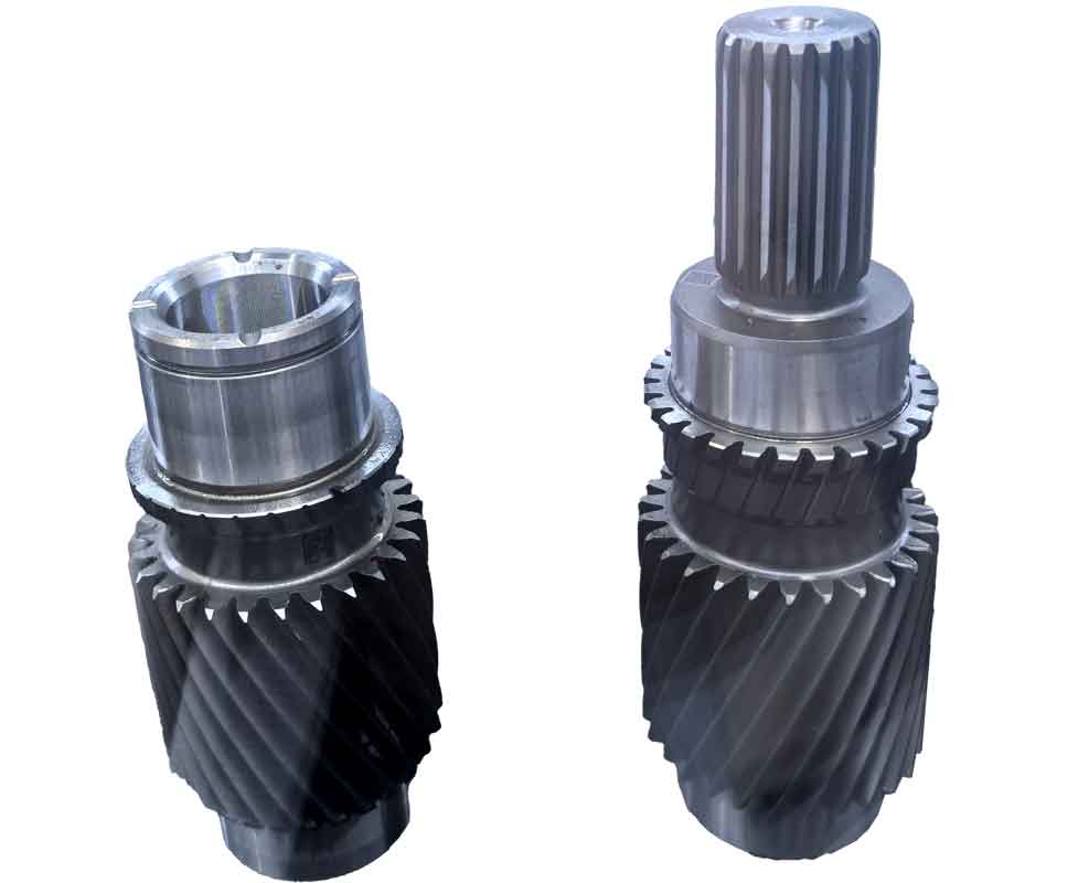
Background and Motivation
In modern gear cutting, the demand for higher accuracy, shorter delivery cycles, and greater product variety continues to rise. Hobs are used in gear cutting for spur gears, helical gears, worm wheels, and many other transmission components. Because the hob geometry is transferred to the gear tooth space during gear cutting, any error in the hob profile, thread pitch, flute angle, or front rake is reflected in the gear tooth accuracy. At the same time, hob manufacturers face small-batch and multi-variety production. Manual programming and multi-machine processing are no longer sufficient for competitive gear cutting tool production.
The most obvious limitations of the conventional route are familiar to me from process planning practice: multiple machines are required, the workpiece is clamped and re-clamped several times, the operator must adjust programs for each hob size, tool interference risks increase, and quality depends heavily on individual skill. These limitations slow down gear cutting tool preparation and make it difficult to guarantee repeatability. I therefore focused on three questions. First, how can the hob turning and milling operations be integrated with fewer setups? Second, how can the machining program automatically adapt to different hob sizes? Third, how can cutting parameters be selected so that machining time is reduced while surface quality and tool life remain acceptable?
My response is an integrated method that connects process design, parametric programming, customized numerical control interface development, virtual simulation, and multi-objective cutting parameter optimization. This method is intended for gear cutting tool manufacturing and, more specifically, for hob production in a turn-milling environment.
Comparative Analysis of Traditional and Integrated Hob Processing
I first analyzed the existing hob process route. The main operations include turning the outer diameter, end faces, shoulders, bore, and undercut grooves; turning the thread; milling the chip flutes; and relieving the tooth profile. In the conventional route, these operations are distributed over a turning center, a CNC lathe, a CNC milling machine, and a relieving lathe. The process capability of each machine may be adequate, but the total route is not optimized as a system. Every additional setup introduces datum variation, clamping deformation, non-cutting time, and the possibility of human error.
| Process Stage | Conventional Route | Integrated Turn-Milling Route | Main Benefit for Gear Cutting Tool Production |
|---|---|---|---|
| Outer diameter, end faces, shoulders, bore | Turning center, multiple clamping operations | Single turn-milling platform with coordinated axes | Fewer datum changes and lower geometric error |
| Thread turning | Separate CNC lathe with a dedicated mandrel | Same platform after turning operations | Better concentricity between bore and thread |
| Chip flute milling | Separate CNC milling machine | Milling spindle and rotary axes on the same platform | Improved flute spacing and front rake consistency |
| Relieving | Special relieving lathe | Retained as a specialized finishing operation | Preserves relief accuracy while simplifying prior stages |
| Programming | Manual or semi-manual, size dependent | Parametric templates with variable substitution | Faster response for multi-variety gear cutting orders |
| Verification | Trial cuts and operator experience | Virtual simulation before real machining | Lower collision risk and higher first-pass success |
The integrated route does not simply place all operations on one machine. It redistributes them according to the kinematic capability of the machine. The turning and threading operations are grouped because they share rotational symmetry and can use the same spindle. The flute milling operation is integrated because the machine has a milling spindle, rotary axes, and sufficient tool storage. The relieving operation remains on a specialized relieving lathe because its cam and linkage characteristics are still superior for final tooth profile relief. This hybrid strategy gives the best balance between process concentration and specialized precision.
Machine Platform and Process Configuration
I selected a BHR700V-type horizontal turn-milling center as the main platform. The machine has dual spindles, an upper tool turret with a B-axis, a lower power turret, linear axes, rotary C axes, and a chain tool magazine. It supports five-axis interpolation and combined turning and milling. The machine structure is suitable for shaft-type workpieces such as hobs because it allows one end to be machined while the other end is supported or transferred. The dual-channel capability also allows turning and milling operations to be coordinated under one numerical control system.
| Machine Feature | Value or Function | Process Meaning |
|---|---|---|
| Maximum swing diameter | 700 mm | Accommodates a wide range of hob blanks |
| Maximum turning diameter | 500 mm | Covers medium and large hob bodies |
| Maximum machining length | 2594 mm | Supports long shaft-type gear cutting tools |
| Linear axis strokes | X1/X2/Z1/Z2/W: 845/270/2680/2600/2400 mm | Provides reach for both spindles and turrets |
| Y-axis stroke | 430 mm, plus or minus 215 mm | Enables off-center milling and virtual Y-axis motion |
| B-axis range | Plus or minus 120 degrees | Allows angular milling and complex tool orientation |
| Tool magazine capacity | 80 tools | Reduces manual tool changes |
| Positioning accuracy | X/Y/Z: 0.003/0.003/0.008 mm | Supports precision gear cutting tool manufacturing |
| B/C repeatability | 5 arc seconds | Maintains angular consistency for flutes and threads |
For the hob process, I divided the integrated route into four logical stages. The first stage is turning all revolution features, including outer diameter, end faces, shoulders, bore, and undercut grooves. The second stage is thread turning. The third stage is chip flute milling. The fourth stage is relieving on a specialized machine. The first three stages are performed on the turn-milling platform. This arrangement removes two or more clamping operations from the conventional route and improves the alignment between the bore, outer diameter, thread, and flutes.
Parametric Programming Based on Group Technology
I used group technology to classify hobs according to common structural and technological features. Although hob dimensions vary, many hobs share the same basic structure: a cylindrical body, a central bore, shoulders, a helical or straight thread, and a set of chip flutes. The machining path logic also remains similar. By treating these similarities as a family, I can create one parametric program template that adapts to many hob sizes. This is especially valuable for gear cutting tool production, where small batch sizes and frequent product changes are common.
Parametric programming works by replacing fixed numerical values with variables. The numerical control system reads the variables, performs arithmetic and logical operations, and generates the required tool motion. For a hob family, the key variables include outer diameter, shoulder diameter, overall length, shoulder length, bore diameter, fitting length, thread height, flute depth, pressure angle, number of starts, cutting speed, feed, and depth of cut. These variables are stored in registers and used by subprograms for facing, boring, groove turning, thread turning, and flute milling.
| Variable Register | Meaning | Role in Gear Cutting Tool Manufacturing |
|---|---|---|
| #50201 | Outer diameter | Controls the outer boundary of the hob body |
| #50202 | Shoulder diameter | Defines the shoulder geometry for clamping and support |
| #50203 | Overall length | Sets axial machining limits |
| #50204 | Shoulder length | Controls shoulder axial length |
| #50206 | Bore diameter | Determines the final bore size for the gear cutting tool |
| #50211 | Pre-bore diameter | Defines the rough boring start |
| #50221 | Flute depth | Controls chip flute depth |
| #50222 | Pressure angle | Relates to the tooth profile of the gear cutting tool |
| #50224 | Workpiece length | Used for axial feed calculations |
| #50226 | Number of thread starts | Determines the lead and feed for thread turning |
| #50228 | Tip width | Controls the thread tip geometry |
| #50230 | Groove top width | Defines flute opening width |
| #50231 | Hand of rotation | Selects left-hand or right-hand hob geometry |
| #50232 | Spindle speed | Provides the base speed for machining operations |
I organized the machining program into a main program and a set of subprograms. The main program initializes the machine, sets units and coordinate modes, calls the required subprograms, and returns the machine to a safe position. The subprograms contain the parametric machining cycles. For example, the facing subprogram uses the outer diameter and shoulder diameter to generate the facing path. The boring subprogram uses the pre-bore diameter and final bore diameter to create a boring cycle. The groove subprogram uses the groove width and axial position to cut the undercut. The thread subprogram uses the thread height, pitch, number of starts, and depth of cut to generate the thread passes. The flute subprogram uses the flute depth, tip width, and hand of rotation to mill the chip flutes.
The thread geometry is particularly important in gear cutting tool production because the hob thread defines the basic rack profile that is transferred to the gear during gear cutting. For a straight hob, the lead angle can be treated as zero in the simplified relation used here. The pitch is therefore related to the module by:
$$p = \frac{\pi m}{\cos \lambda_0}$$
For the straight hob case, the lead angle term is simplified, giving:
$$p = \pi m$$
The feed per workpiece revolution is related to the pitch and the number of thread starts by:
$$f = g p = g \pi m$$
where \(m\) is the module, \(g\) is the number of starts, and \(f\) is the axial feed. This relation allows the parametric program to calculate feed directly from the hob module and number of starts. It also helps maintain consistency between the thread turning program and the intended gear cutting geometry.
Parametric Machining Time and Pass Calculation
For the turning and threading cycles, I used parametric expressions to estimate machining time and the number of passes. The thread-turning time can be written as:
$$T_1 = \frac{(l + l_1 + l_2)i}{p n g}$$
where \(l\) is the thread length, \(l_1\) is the approach length, \(l_2\) is the overrun length, \(i\) is the number of passes, \(p\) is the pitch, \(n\) is the spindle speed, and \(g\) is the number of starts. In the process planning stage, I used an approach length approximately equal to three times the pitch and an overrun length of about 5 mm. The number of passes is related to the thread height and the depth of cut by:
$$i = \frac{h}{a_p}$$
where \(h\) is the total thread height and \(a_p\) is the depth of cut per pass. These equations allow the parametric program to calculate the required number of passes and estimate the cycle time before actual machining. They also provide the basis for the multi-objective optimization described later.
For the turning operations, I created subprograms for facing, boring, and groove turning. Each subprogram uses variables from the register table. The facing subprogram performs a series of axial passes until the shoulder length is reached, then finishes the surface. The boring subprogram moves the boring tool to the pre-bore diameter, cuts to the required bore length, retracts, and repeats until the final bore diameter is achieved. The groove subprogram cuts the undercut groove and retracts safely. Because these subprograms are parametric, they can be reused for different hob sizes without rewriting the entire program.
| Subprogram Function | Key Variables | Output Motion |
|---|---|---|
| Facing | Outer diameter, shoulder diameter, shoulder length | Axial facing passes and finish pass |
| Boring | Pre-bore diameter, bore diameter, bore length | Radial incremental boring and axial feed |
| Groove turning | Groove width, groove position, bore diameter | Radial and axial groove cutting |
| Thread turning | Module, starts, thread height, depth of cut | Synchronized spindle and axial thread passes |
| Flute milling | Flute depth, tip width, hand of rotation | Indexed milling around the hob axis |
Customized Interface and Zero-Programming Machining
Although parametric programming reduces the need for manual editing, the operator still needs an interface that is easy to use on the shop floor. I therefore developed a customized interface using an HNCSCADA-type configuration environment. The interface is organized around the actual hob process. The operator selects the operation, enters the hob parameters, confirms the tool and fixture data, and starts the cycle. The interface then loads the corresponding parametric program, assigns the variables, and executes the machining process. In this way, the operator does not need to write or edit G-code for each new hob. I refer to this as zero-programming machining for gear cutting tool production.
The interface includes several functional zones. The first zone is program selection, where the operator chooses turning, thread turning, or flute milling. The second zone is parameter input, where the operator enters dimensions such as outer diameter, bore diameter, length, module, number of starts, and flute number. The third zone is data exchange, which writes the entered values into the numerical control variable registers. The fourth zone is status display, which shows the selected tool, current operation, and progress. The fifth zone is safety confirmation, which checks whether the entered values are within the allowable range.
| Interface Function | Operator Action | System Response |
|---|---|---|
| Operation selection | Select turning, threading, or flute milling | Loads the corresponding parametric program template |
| Parameter entry | Input hob dimensions and process data | Validates values and writes them to registers |
| Tool selection | Confirm or select tool number | Checks tool offset and tool life data |
| Program generation | Press the generate or start button | Builds the executable numerical control program |
| Cycle start | Press cycle start | Runs the machining process under monitoring |
| Data exchange | Read or write parameter files | Stores hob-family data for future orders |
I designed the interface so that the same parameter set can be reused for a hob family. For example, when the module and number of starts change, the thread-turning subprogram recalculates pitch, feed, and pass count automatically. When the outer diameter and bore diameter change, the turning subprogram adjusts the facing and boring cycles. When the flute number changes, the flute milling subprogram adjusts the indexing angle. This reduces programming time and minimizes the chance of manual input errors. It also supports the small-batch, multi-variety production pattern that is common in gear cutting tool manufacturing.
The interface was designed with a hierarchical menu structure. The main menu contains the three main operations. Each operation screen contains parameter fields, tool information, and start buttons. The operator can move between screens without leaving the machining context. This is important because a hob may require turning, threading, and flute milling in sequence. The interface keeps the process data available so that the operator can verify the complete route before starting the first cut.
Virtual Machining Simulation and Verification
Before real machining, I built a virtual turn-milling environment. I created the machine tool geometry in a CAD environment and exported the components in STL format. I then assembled the machine model in a VERICUT-type simulation environment according to the kinematic topology. The model includes the bed, spindles, turrets, linear axes, rotary axes, tool magazine, and clamping devices. The simulation environment allows me to check tool paths, detect collisions, verify coordinate offsets, and observe the material removal process.
The machine model is organized as a component tree. The bed is the base. The Z1 axis carries the milling spindle assembly. The Y axis is mounted on the Z1 axis, and the X1 axis is mounted on the Y axis. The B-axis turret is mounted on the X1 axis. The C1 spindle and chuck form a separate branch. The Z2 and X2 axes carry the lower turret. The W axis and C2 spindle form the second spindle branch. This topology reflects the actual machine structure and allows the simulation to reproduce the relative motion between the tool and the workpiece.
| Simulation Element | Configuration | Purpose |
|---|---|---|
| Machine model | CAD geometry exported as STL | Visual and collision representation |
| Control system | Dual-channel numerical control behavior | Separate milling and turning channels |
| Milling channel | X1, Y, Z1, B, and milling spindle | Flute milling and auxiliary milling |
| Turning channel | X2, Z2, and lower turret | Turning and thread turning |
| Shared axes | C1 and C2 | Workpiece indexing and spindle rotation |
| Virtual Y axis | Combined motion of X and Y axes | Correct off-center milling motion |
| Synchronization | WAITM-type macro instructions | Coordinate two channels during combined cycles |
| Work offsets | G54 and G55 | Define two programming zeros for two ends |
I configured the dual-channel behavior carefully. The milling channel and turning channel can run independently or synchronously. For hob machining, the turning channel performs the turning and thread-turning operations, while the milling channel performs the flute milling operations. The shared C axes allow the workpiece to be indexed accurately. The virtual Y axis is configured because the machine uses an inclined axis arrangement, and the numerical control system transforms the commanded Y motion into coordinated X and Y motion. If this transformation is not configured correctly, the simulated tool path will deviate from the actual path.
I also configured macro instructions for synchronization. In a dual-channel machine, one channel may need to wait for the other before a combined operation can proceed. The synchronization macro provides a communication marker between channels. When both channels reach the same marker, the subsequent motion is allowed. This prevents collisions and ensures that the workpiece is properly positioned before the second operation begins. The dual C-axis configuration is also defined so that the main spindle and the counter-spindle are distinguished correctly. The work offsets are set as G54 and G55 for the two ends of the hob. This is necessary because the hob may be machined from both ends, and each end requires its own programming zero.
After the machine model and control configuration were complete, I imported the parametric numerical control programs into the simulation environment. I ran the turning cycle, the thread-turning cycle, and the flute milling cycle. During the first simulation runs, I observed potential interference between the end-facing tool and the boring tool because of their different mounting orientations. I adjusted the tool positions in the turret so that the boring tool was away from the facing tool during the turning cycle. I also adjusted the approach and retract paths to avoid collisions with the chuck and tailstock. These adjustments are difficult and expensive to discover on a real machine, but they are straightforward in a virtual environment.
The simulation results confirmed that the integrated process is feasible. The tool paths followed the intended geometry, the threads were generated correctly, and the flutes were indexed properly. The virtual workpiece after machining matched the reference model within the simulation tolerance. I used the compare function to check for over-cut and under-cut. The comparison showed no unacceptable deviation. This validation gave me confidence to proceed to real machine trials.
Real Machine Validation
I then validated the method on an actual turn-milling machine. The customized interface and parametric programs were packaged and loaded into the numerical control system. The operator selected the hob type, entered the parameters, and started the cycle. The machine completed the turning, threading, and flute milling operations according to the integrated route. The actual machining results were consistent with the simulation. The interface was easy to operate, the program responded correctly to parameter changes, and the machining process was stable. This validation confirmed that the combination of parametric programming, customized interface, and virtual simulation is practical for gear cutting tool production.
The main benefits observed in real machining were reduced setup time, fewer clamping operations, lower programming effort, and better repeatability. Because the program adapts to the hob parameters, the operator does not need to edit the program for each new size. Because the process is integrated, the workpiece does not need to be moved between machines for the first three operations. This reduces the chance of datum errors and improves the concentricity between the bore, outer diameter, thread, and flutes. These improvements are directly relevant to gear cutting accuracy because the hob geometry is transferred to the gear during gear cutting.
Multi-Objective Cutting Parameter Optimization
After establishing the process and programming method, I focused on cutting parameter optimization for the thread-turning operation. Thread turning is one of the most time-consuming steps in hob manufacturing. It also has a strong influence on surface quality and tool life. I selected cutting speed, depth of cut, and feed as the main variables. The objectives were to minimize thread-turning time and maximize tool life. The constraints were surface roughness, spindle speed, and depth of cut.
The machining time objective is:
$$\min T_1 = \frac{(l + l_1 + l_2)i}{p n g}$$
The tool life objective is based on an extended Taylor-type model. I used the following form:
$$T_2 = k v_c^a f^b a_p^c$$
where \(T_2\) is the tool life or regrinding interval, \(v_c\) is the cutting speed, \(f\) is the feed, \(a_p\) is the depth of cut, and \(k\), \(a\), \(b\), and \(c\) are coefficients determined from machining data. The cutting speed is related to spindle speed and workpiece diameter by:
$$v_c = \frac{\pi d n}{1000}$$
Substituting this relation into the tool life model gives:
$$T_2 = k \left(\frac{\pi d n}{1000}\right)^a f^b a_p^c$$
Using the data collected from actual thread-turning operations, I fitted the coefficients. The fitted model was:
$$T_2 = 2.9979 \left(\frac{\pi d n}{1000}\right)^{0.3983} f^{-0.2777} a_p^{0.0700}$$
The negative exponent on feed indicates that increasing feed tends to reduce tool life, while the positive exponents on cutting speed and depth of cut reflect the combined influence of thermal and mechanical loading. The model is not a universal law, but it is a useful local approximation for the selected workpiece material, tool material, and machine condition.
The surface roughness constraint is based on the theoretical relation between feed and tool nose radius:
$$Ra = \frac{f^2}{32 r_\epsilon}$$
where \(r_\epsilon\) is the tool nose radius. To ensure that the thread surface meets the required quality, I imposed:
$$Ra \le Ra_{\max} = 20 \mu m$$
The spindle speed constraint was set according to the machine capability and the threading process:
$$10 \le n \le 50 \text{ r/min}$$
The depth of cut constraint was set to avoid unstable cutting and excessive tool load:
$$0.1 \le a_p \le 0.6 \text{ mm}$$
The complete optimization problem can therefore be summarized as a multi-objective problem with two objectives and three constraints. The first objective is to minimize thread-turning time. The second objective is to maximize tool life. The constraints ensure that surface roughness remains acceptable, spindle speed remains within the machine range, and depth of cut remains within a stable cutting range.
| Optimization Element | Expression or Range | Interpretation |
|---|---|---|
| Objective 1 | \(\min T_1\) | Reduce thread-turning time |
| Objective 2 | \(\max T_2\) | Extend thread tool life |
| Variable | \(v_c\), \(a_p\), \(f\) | Cutting speed, depth of cut, and feed |
| Surface roughness constraint | \(Ra \le 20 \mu m\) | Maintain thread surface quality |
| Spindle speed constraint | \(10 \le n \le 50\) r/min | Stay within stable threading range |
| Depth of cut constraint | \(0.1 \le a_p \le 0.6\) mm | Avoid unstable cuts and excessive load |
| Pass count relation | \(i = h / a_p\) | Relate depth of cut to number of passes |
I solved the optimization problem using a genetic algorithm. The genetic algorithm is suitable for this problem because the objectives are nonlinear, the constraints are inequality constraints, and the search space is not convex. The algorithm evaluates a population of candidate parameter sets. Each candidate is checked against the roughness, speed, and depth constraints. If a candidate violates the roughness constraint, its fitness is reduced so that it is less likely to survive to the next generation. If a candidate satisfies the constraints, it is ranked according to the two objectives. Over successive generations, the algorithm favors parameter sets that reduce machining time and extend tool life.
I used the optimization routine to calculate the best spindle speed and depth of cut for each hob in the selected family. From these values, I calculated cutting speed, number of passes, thread-turning time, tool life, and surface roughness. The results were then compared with the original machining data.
| Hob Case | Outer Diameter (mm) | Thread Height (mm) | Optimized Speed (r/min) | Optimized Depth (mm) | Passes | Optimized Time (min) | Optimized Tool Life (min) | Surface Roughness (\(\mu m\)) |
|---|---|---|---|---|---|---|---|---|
| 1 | 60 | 9.13 | 40 | 0.40 | 23 | 9.87 | 82.34 | 4.28 |
| 2 | 52 | 10.42 | 22 | 0.45 | 23 | 58.34 | 80.12 | 4.11 |
| 3 | 70 | 3.16 | 42 | 0.50 | 6 | 18.98 | 118.23 | 3.11 |
| 4 | 120 | 13.20 | 28 | 0.45 | 29 | 25.12 | 110.45 | 4.05 |
| 5 | 55 | 3.30 | 48 | 0.35 | 9 | 22.34 | 112.34 | 3.33 |
| 6 | 83 | 11.48 | 18 | 0.48 | 24 | 68.23 | 109.12 | 4.77 |
| 7 | 58 | 7.70 | 42 | 0.35 | 22 | 7.98 | 108.45 | 3.99 |
| 8 | 65 | 8.31 | 48 | 0.35 | 24 | 8.98 | 115.67 | 3.77 |
| 9 | 82 | 10.78 | 42 | 0.50 | 21 | 5.89 | 90.23 | 4.03 |
| 10 | 85 | 10.71 | 42 | 0.50 | 21 | 4.98 | 93.45 | 4.08 |
| 11 | 100 | 9.29 | 26 | 0.45 | 21 | 27.34 | 88.45 | 4.56 |
| 12 | 90 | 7.27 | 48 | 0.50 | 14 | 3.98 | 114.56 | 3.44 |
| 13 | 120 | 9.35 | 35 | 0.55 | 17 | 7.89 | 170.23 | 3.05 |
| 14 | 70 | 4.46 | 19 | 0.48 | 9 | 36.54 | 85.45 | 4.44 |
| 15 | 120 | 13.20 | 40 | 0.55 | 24 | 12.34 | 82.34 | 3.66 |
| 16 | 150 | 9.77 | 28 | 0.45 | 22 | 34.56 | 107.23 | 4.33 |
| 17 | 80 | 9.89 | 48 | 0.35 | 28 | 12.34 | 95.45 | 3.55 |
| 18 | 80 | 6.63 | 48 | 0.45 | 15 | 6.78 | 96.78 | 3.88 |
| 19 | 80 | 4.94 | 48 | 0.45 | 11 | 4.89 | 94.56 | 3.92 |
| 20 | 80 | 8.41 | 15 | 0.38 | 22 | 56.78 | 103.45 | 5.11 |
| 21 | 80 | 6.31 | 42 | 0.45 | 14 | 11.23 | 110.23 | 3.96 |
| 22 | 90 | 8.15 | 42 | 0.45 | 18 | 12.34 | 135.45 | 4.11 |
Result Analysis and Discussion
The optimization results showed a clear improvement in thread-turning efficiency. For most cases, the optimized thread-turning time was lower than the original time. The average reduction was about 18.70 percent. The best case showed a reduction of more than 80 percent, which indicates that the original parameters were far from optimal. Some cases showed only a small improvement because the original parameters were already close to a stable operating point. The tool life results also improved on average by about 4.60 percent. This means that the optimized parameters not only reduced machining time but also reduced the tool wear rate in many cases.
| Metric | Before Optimization | After Optimization | Change |
|---|---|---|---|
| Thread-turning time | Relatively long | Average reduction of 18.70 percent | Higher productivity |
| Tool life | Frequent regrinding | Average increase of 4.60 percent | Longer tool life and fewer interruptions |
| Feed | Conservative | Moderately increased | Better material removal rate |
| Surface roughness | Within specification | Maintained below 20 micrometers | Quality constraint satisfied |
I also examined the cases where the optimization did not improve tool life. One case showed a slight decrease in tool life. This occurred because the algorithm increased the depth of cut to reduce the number of passes, which increased the mechanical load on the tool. The result shows that the trade-off between productivity and tool life is not uniform across all hob sizes. For large hobs, the depth of cut may be limited by machine stiffness, tool holder rigidity, or thermal effects. For small hobs, the thread-turning time can be reduced more easily because the removed volume is smaller and the spindle speed can be increased within the stable range.
The influence of cutting speed was also significant. In general, increasing cutting speed reduces machining time but also increases tool wear. The genetic algorithm found a balance by selecting speeds that were high enough to reduce cycle time but not so high that tool life dropped sharply. The feed was increased in many cases because the surface roughness constraint still allowed it. The depth of cut was adjusted according to the thread height and the number of passes. In some cases, a larger depth of cut reduced the number of passes and shortened the cycle time, but it also increased the cutting force. This is why the optimization model included both objectives rather than minimizing time alone.
The surface roughness constraint was satisfied in all optimized cases shown in the result table. The calculated roughness values remained below 20 micrometers. This is important for gear cutting tool quality because the thread surface influences the contact condition during gear cutting. A rough thread surface can increase friction, cause uneven load distribution, and reduce the effective accuracy of the gear cutting process. By keeping roughness within the specified limit, the optimization improves productivity without sacrificing the functional requirement of the hob.
Integration of Process Design, Programming, Simulation, and Optimization
The main contribution of my work is the integration of several digital manufacturing methods into one workflow for gear cutting tool production. The workflow begins with process analysis. The traditional route is decomposed into operations, and the operations are reorganized according to the capability of the turn-milling platform. The second step is group technology classification. Hobs with similar structure and process logic are grouped into a family. The third step is parametric programming. The common features of the family are converted into variables, and the machining cycles are written as reusable subprograms. The fourth step is customized interface development. The operator interacts with the numerical control system through a simple, process-oriented interface. The fifth step is virtual simulation. The machine model, control channels, tools, fixtures, and programs are verified before real machining. The sixth step is cutting parameter optimization. The thread-turning parameters are tuned to reduce cycle time and extend tool life while maintaining surface quality.
| Workflow Stage | Input | Method | Output |
|---|---|---|---|
| Process analysis | Traditional hob route | Operation decomposition and regrouping | Integrated turn-milling route |
| Group technology | Hob family data | Feature extraction and classification | Common parameter set |
| Parametric programming | Variable register table | Main program and subprogram templates | Adaptive numerical control programs |
| Interface development | Operator requirements | HNCSCADA-type configuration | Zero-programming machining interface |
| Virtual simulation | CAD model and control data | VERICUT-type machining simulation | Verified tool paths and collision-free process |
| Parameter optimization | Machining data | Genetic algorithm and multi-objective model | Optimized speed, feed, and depth of cut |
This workflow is particularly suitable for gear cutting tool manufacturing because hobs are high-value tools with complex geometry and strict quality requirements. The cost of a failed trial cut is high. The cost of an incorrect program is high. The cost of an unstable process is high. By moving much of the trial-and-error into the virtual environment and by making the program adapt to the hob family, I can reduce these costs and improve the overall efficiency of gear cutting tool production.
Practical Implications for Gear Cutting
From the perspective of gear cutting, the hob is the first link in the accuracy chain. If the hob is manufactured with fewer setups, better concentricity, and more consistent thread geometry, the gear cutting process becomes more stable. The integrated turn-milling process improves the alignment between the bore and the thread because both are machined on the same platform with minimal reclamping. The parametric programming method ensures that the thread and flute geometry are generated from the correct variables rather than from manually edited values. The simulation step ensures that the tool does not collide with the workpiece or fixture. The optimization step ensures that the thread-turning parameters are selected for both efficiency and tool life.
These improvements have a direct effect on gear cutting quality. A hob with accurate thread pitch produces a gear tooth with accurate pitch. A hob with consistent flute spacing produces a gear tooth with stable cutting conditions. A hob with proper front rake reduces cutting force and improves surface finish during gear cutting. Therefore, the methods described here are not isolated manufacturing improvements. They support the final gear cutting operation by improving the tool that performs the cutting.
Limitations and Further Development
I also recognize several limitations. First, the optimization model is based on a limited set of machining data. The coefficients in the tool life equation are local to the selected material, tool, and machine configuration. A larger data set would improve the generality of the model. Second, the virtual simulation is only as accurate as the machine model and control configuration. Small differences in tool offsets, fixture stiffness, and thermal behavior may still cause deviations in real machining. Third, the customized interface requires careful maintenance. If the hob family changes, the variable definitions and subprograms must be updated. Fourth, the real machining validation was performed on a limited number of hob cases. More extensive production trials would be useful to confirm the long-term stability of the method.
Future work could extend the method in several directions. One direction is to collect more data from actual gear cutting tool production and use machine learning to predict tool life and surface roughness more accurately. Another direction is to integrate adaptive control so that the machine can adjust feed or speed in real time based on cutting force or vibration. A third direction is to expand the parametric family to include more hob types, such as multi-start hobs, helical hobs, and special profile hobs. A fourth direction is to link the hob manufacturing data with the gear cutting process model so that the hob geometry can be optimized for a specific gear cutting application.
Conclusions
I analyzed the traditional hob manufacturing route and identified its main weaknesses: multiple machines, repeated clamping, manual programming, and unstable parameter selection. I designed an integrated turn-milling process that concentrates the turning, threading, and flute milling operations on one platform while retaining specialized relieving for final tooth profile accuracy. I applied group technology to extract the common features of a hob family and created parametric programs that adapt to different hob sizes. I developed a customized interface that allows the operator to enter parameters and generate machining programs without manual G-code editing. I built a virtual turn-milling simulation environment, configured the dual-channel control behavior, verified the tool paths, and validated the process on a real machine. I then optimized the thread-turning parameters using a multi-objective genetic algorithm.
The optimization reduced the average thread-turning time by about 18.70 percent and increased average tool life by about 4.60 percent, while maintaining surface roughness below the specified limit. The integrated process reduced setup time, improved dimensional consistency, and lowered programming effort. For gear cutting tool production, these improvements mean faster delivery, more stable quality, and better support for the final gear cutting operation. The method provides a practical path toward intelligent, flexible, and efficient manufacturing of hobs for modern gear cutting.