
In this study, I focused on the high-precision phase matching between the internal spline and the external teeth of a diesel engine valve gear. The valve gear is a critical component of the valve train. Its function is to open and close the intake and exhaust valves according to the engine firing order. The timing of the valve phase strongly affects the time-area integral and thus the power performance of the engine. The gear cutting process for such a component must meet strict size, form, and angular requirements. The material selected for the valve gear was 20CrMnTi carburizing steel. The structure is complex, the number of operations is large, and the precision is high. Among all requirements, the phase angle between the center of the marked external tooth and the center of the corresponding internal spline groove is the most difficult to achieve. I analyzed the process route and drawing requirements, then designed dedicated fixed-tooth fixtures, pull card heads, and internal spline broaches. These tools and fixtures solved the gear cutting difficulty and satisfied the trial production requirements.
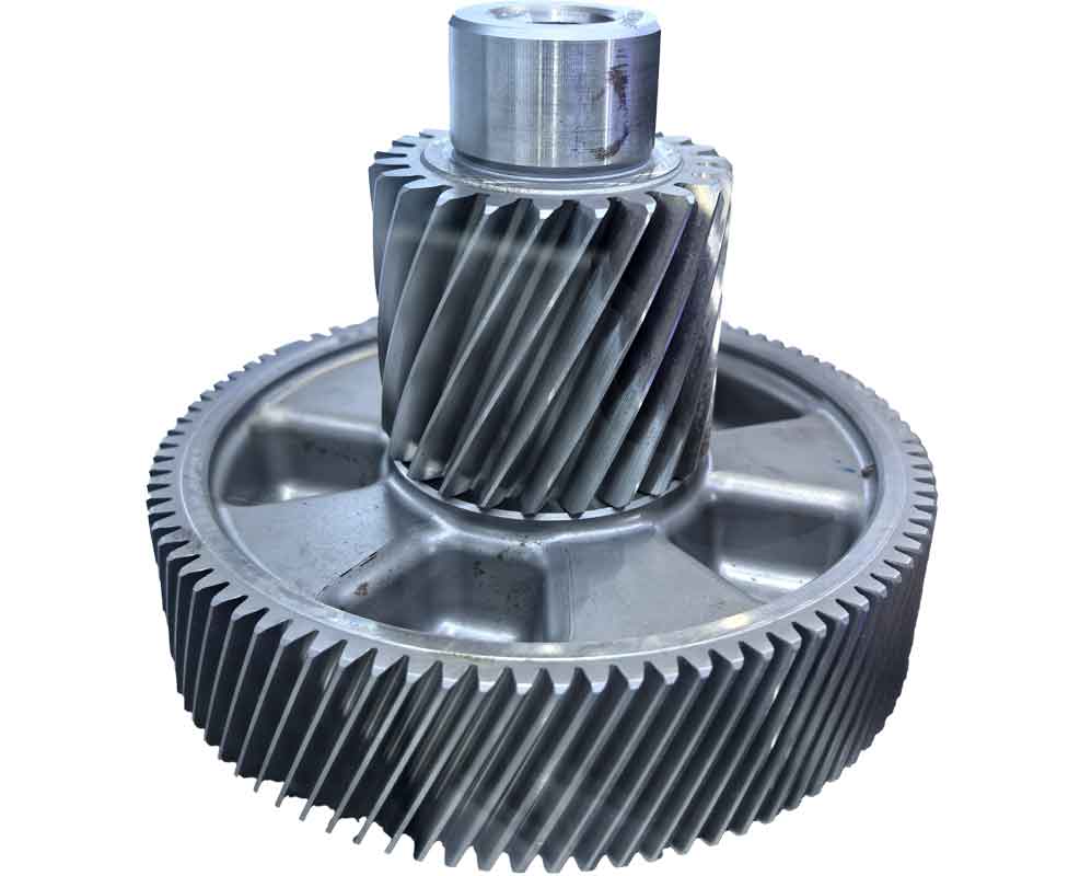
Design precision requirements
The main design precision indices of the valve gear are summarized in Table 1. The external teeth must reach grade 6HK according to GB/T 10095-1988. The internal spline must reach grade 7H according to GB/T 3478.1-2008. The two end datum journals have a diameter tolerance of 2-50f7 (-0.025/-0.05) mm. The radial runout of each journal relative to the internal spline datum is 0.02 mm, and the coaxiality tolerance between the two journals is 0.03 mm. The phase angle between the marked external tooth center and the corresponding internal spline groove center must be within ±10′. This phase requirement is the core challenge for gear cutting and for the entire manufacturing chain.
| Characteristic | Requirement | Standard / Method |
|---|---|---|
| External teeth | Grade 6HK | GB/T 10095-1988 |
| Internal spline | Grade 7H | GB/T 3478.1-2008 |
| Journal diameter | 2-50f7 (-0.025/-0.05) mm | Micrometer |
| Radial runout | 0.02 mm | Taper spline mandrel + dial indicator |
| Coaxiality | 0.03 mm | Runout checker |
| Phase angle | ±10′ | CMM with expanding mandrel |
The phase angle tolerance in radians is
$$\Delta \phi_{tol} = 10′ = \frac{10}{60}^\circ = 0.1667^\circ = 2.909 \times 10^{-3} \text{ rad}.$$
At a nominal radius of 50 mm, the allowable tangential displacement is
$$e_{tol} = r \Delta \phi_{tol} = 50 \times 2.909 \times 10^{-3} = 0.145 \text{ mm}.$$
This value is the total allowable tangential error at the reference radius. However, because the errors from the machine, fixture, broach, workpiece, and measurement stack up, the individual allocations must be much smaller. I used an error budget to distribute the tolerance among the contributors. This is a key step in robust gear cutting process design.
Material and heat treatment foundation
The valve gear material was 20CrMnTi carburizing steel. This material provides a tough core and a hard, wear-resistant case. The typical chemical composition is given in Table 2. The carburizing and quenching cycle is critical for the internal spline and external teeth. I used vacuum furnace non-oxidizing quenching to avoid surface decarburization and oxidation. The heat treatment parameters are summarized in Table 3.
| Element | Content (%) |
|---|---|
| C | 0.17-0.23 |
| Si | 0.17-0.37 |
| Mn | 0.80-1.10 |
| Cr | 1.00-1.30 |
| Ti | 0.04-0.10 |
| P | ≤0.035 |
| S | ≤0.035 |
| Parameter | Value |
|---|---|
| Carburizing temperature | 920-930 °C |
| Carburizing time | According to case depth |
| Effective case depth | 0.8-1.2 mm |
| Surface hardness | 58-62 HRC |
| Core hardness | 30-45 HRC |
| Quenching medium | Vacuum furnace, high-pressure gas |
| Tempering temperature | 160-200 °C |
The dimensional change during quenching can be approximated by
$$\Delta L = \alpha L \Delta T,$$
where \(\alpha\) is the coefficient of thermal expansion, \(L\) is the characteristic length, and \(\Delta T\) is the temperature change. For steel, \(\alpha \approx 11 \times 10^{-6} /^\circ C\). For a 50 mm dimension and a temperature change of 800 °C, the free thermal contraction would be
$$\Delta L = 11 \times 10^{-6} \times 50 \times 800 = 0.44 \text{ mm}.$$
This is much larger than the final tolerance, so the quenching process must be controlled to avoid distortion. The actual distortion depends on the phase transformation and the cooling uniformity. Vacuum quenching provides uniform cooling and low oxidation, which reduces distortion. The spline calibration broach then corrects any remaining small distortion. This two-step approach is essential for gear cutting because the internal spline is the angular datum for the external teeth.
Process route and analysis
Based on the structural features and precision requirements, I developed the process route shown in Table 4. The internal spline is the datum for machining the external teeth and the two end journals. Therefore, the accuracy of the internal spline is the foundation of the whole gear cutting chain. The two end journals are ground on a high-precision taper spline mandrel. The external teeth are ground on a high-precision spline-expanding gear grinding mandrel. The internal spline is machined on an L620 horizontal broaching machine using a form broach. The hydraulic pull rod transmits the pulling force to the broach body through the pull card head. The broach performs linear motion, and the radial feed is realized by the tooth rise per cutter tooth. This method provides high efficiency and stable size accuracy for the internal spline. The critical issue is the angular position of the internal spline groove relative to the external tooth center. This requires accurate limiting of the broach tooth center and the workpiece external tooth center. The cumulative error of the machine, fixture, tool, and workpiece must remain within the allocated budget for gear cutting.
| Step | Operation | Purpose |
|---|---|---|
| 1 | Forging | Form blank |
| 2 | Rough machining | Remove stock |
| 3 | Normalizing | Improve machinability and refine grain |
| 4 | Finish machining | Prepare for hobbing |
| 5 | Gear hobbing | Form external teeth |
| 6 | Carburizing | Case hardening |
| 7 | Turning carburized layer | Remove excessive case |
| 8 | Internal spline machining | Broach internal spline |
| 9 | Vacuum quenching | Harden with low oxidation |
| 10 | Spline calibration | Correct distortion |
| 11 | Finish grinding journals | Achieve journal tolerances |
| 12 | Finish grinding teeth | Achieve grade 6HK |
| 13 | Magnetic particle inspection | Detect cracks |
| 14 | Final inspection | Verify all requirements |
External gear cutting parameters
The external teeth are first hobbed and then ground. The hobbing operation removes most of the stock, while the grinding operation achieves the final grade 6HK accuracy. The gear geometry is defined by the module, number of teeth, pressure angle, and helix angle. The pitch diameter is
$$d = m z,$$
where \(m\) is the module and \(z\) is the number of teeth. The addendum and dedendum are
$$h_a = m,$$
$$h_f = 1.25 m.$$
The base diameter is
$$d_b = d \cos \alpha,$$
where \(\alpha\) is the reference pressure angle. The transverse contact ratio is
$$\varepsilon_\alpha = \frac{\sqrt{r_{a1}^2 – r_{b1}^2} + \sqrt{r_{a2}^2 – r_{b2}^2} – a \sin \alpha_t}{p_{bt}},$$
where \(r_a\) is the tip radius, \(r_b\) is the base radius, \(a\) is the center distance, and \(p_{bt}\) is the base pitch. These parameters ensure proper meshing and load capacity. The gear cutting process for the external teeth must keep the tooth center aligned with the internal spline datum. This is why the phase angle control is critical.
| External gear parameter | Value or formula |
|---|---|
| Module | \(m\) |
| Number of teeth | \(z\) |
| Pressure angle | \(\alpha\) |
| Pitch diameter | \(d = m z\) |
| Base diameter | \(d_b = d \cos \alpha\) |
| Addendum | \(h_a = m\) |
| Dedendum | \(h_f = 1.25 m\) |
| Tooth thickness | \(s = \pi m / 2\) |
Internal spline process optimization
During the first two trial rounds, the main problem was heat treatment distortion and surface oxidation of the internal spline. With ordinary quenching, the spline teeth suffered from surface decarburization and oxidation. The measured cross-pin distance exceeded the upper process limit in 100% of the parts, causing batch scrap. To solve this, I designed and manufactured a spline broach and a spline calibration broach. I also changed the quenching process to vacuum furnace non-oxidizing quenching. After this optimization, the trial results were very good. The internal spline size accuracy, profile error, lead error, pitch error, and roughness met the process requirements. This provided a high-precision datum for subsequent finish operations and improved the overall capability of gear cutting.
The cross-pin distance is a functional measurement of spline size. For an involute spline, the theoretical cross-pin distance can be expressed as
$$M = m z \cos \alpha \left( \frac{\cos \alpha}{\cos \alpha_M} – 1 \right) + d_p,$$
where \(m\) is the module, \(z\) is the number of teeth, \(\alpha\) is the reference pressure angle, \(\alpha_M\) is the pressure angle at the pin center, and \(d_p\) is the pin diameter. The measured value must lie between the go and no-go limits. Vacuum quenching reduced the oxidation layer and distortion, so the cross-pin distance remained within tolerance. This step was essential for reliable gear cutting because the internal spline is the rotational datum.
Broach geometry and cutting force
The spline broach material was high-speed steel. The total number of spline teeth was 75, including 70 cutting teeth and 5 calibration teeth. The spline pitch was 7.5 mm. The cutting edge inclination and adjacent tooth rise angle met the broaching design precision requirements. The key to the broach design was the size accuracy of the head moving pair plane. The perpendicularity between this moving pair plane and the broach tooth center was required to be 0.02 mm. The broach structure and geometry are summarized in Table 5 and Table 6.
| Parameter | Value |
|---|---|
| Material | High-speed steel |
| Total teeth | 75 |
| Cutting teeth | 70 |
| Calibration teeth | 5 |
| Pitch | 7.5 mm |
| Head moving pair perpendicularity to tooth center | 0.02 mm |
| Cutting edge inclination | According to design |
| Tooth rise | According to design |
| Geometric feature | Typical value |
|---|---|
| Rake angle | 12-15° |
| Clearance angle | 3-5° |
| Tooth height | Calculated from spline depth |
| Fillet radius | 0.2-0.5 mm |
| Chip space depth | 3-5 times tooth rise |
| Tooth width | According to spline width |
The broach tooth rise determines the chip load per tooth. For a broach with total stock removal \(h\) and \(N_c\) cutting teeth, the nominal rise per tooth is
$$a_f = \frac{h}{N_c}.$$
The cutting force per tooth is approximately
$$F_c = K_c a_f b,$$
where \(K_c\) is the specific cutting force and \(b\) is the cutting width. The total broaching force is
$$F_{total} = \sum_{i=1}^{N_c} F_{c,i}.$$
For a typical case with \(K_c = 2000 \text{ N/mm}^2\), \(a_f = 0.05 \text{ mm}\), and \(b = 10 \text{ mm}\), the force per tooth is
$$F_c = 2000 \times 0.05 \times 10 = 1000 \text{ N}.$$
If 14 teeth are in cut at the same time, the total force is
$$F_{total} = 14 \times 1000 = 14000 \text{ N}.$$
The machine hydraulic pull rod must provide enough force to overcome this total force and friction. The pull card head and broach moving pair must transmit this force without angular slip. The rotational limit provided by the semi-cylindrical insert plate is therefore critical for phase accuracy in gear cutting.
Pull card head design
By analyzing the working principle of the L620 horizontal broaching machine, I determined that the pull card head is the intermediate carrier for power transmission between the hydraulic pull rod and the broach. To transmit precision efficiently and accurately, I measured the hydraulic pull rod bore diameter as 50.01 mm. The connection shaft diameter of the pull card head was designed as 50 0/-0.02 mm, which satisfies the clearance fit requirement. The rotational limit of the pull card head is achieved by a semi-cylindrical locating insert plate. During operation, the two cylindrical surfaces of the semi-cylindrical locating insert plate fit closely with the keyway holes of the pull card head and the hydraulic pull rod, achieving precise rotational limit. The pull card head structure parameters are summarized in Table 7.
| Parameter | Value | Function |
|---|---|---|
| Hydraulic pull rod bore | 50.01 mm | Measured |
| Pull card head shaft | 50 0/-0.02 mm | Clearance fit |
| Rotational limit | Semi-cylindrical insert | Precise angular limit |
| Concentricity of moving pair | 0.015 mm | Axis alignment |
| Perpendicularity of moving plane | 0.02 mm | Tooth center alignment |
In the moving pair design between the pull card head and the broach head, the hydraulic pull rod, pull card head, and broach axis must theoretically be on the same axis. Therefore, I added a concentricity requirement of 0.015 mm to the moving pair solid surface, with the datum being the mating surface between the pull card head and the hydraulic pull rod. The rotational limit precision of the broach requires that the perpendicularity between the moving pair plane and the keyway center plane of the pull card head be 0.02 mm. This is the key point of the pull card head design. The high-precision geometric tolerance of the pull card head ensures the concentricity of the hydraulic pull rod axis and the broach body axis, realizing precise and efficient conversion of the broaching machine power into broach cutting force. This directly improves the angular stability of gear cutting.
Fixed tooth fixture design
The workpiece tooth center positioning required a dedicated fixed tooth fixture. The technical difficulties and solutions in the design of this fixture are described below.
Precision assembly of the fixed tooth fixture with the L620 broaching machine stop arm flange
The fixed tooth fixture must be reusable and easy to assemble and disassemble. Considering the structural features of the L620 horizontal broaching machine body stop arm flange, the fit between the fixture inner bore and the shaft neck was selected as a clearance fit. The machine body stop arm flange bore size accuracy was 130H6 according to the machine operation manual. Therefore, the shaft neck size accuracy of the fixed tooth fixture was selected as 130h6 to meet the assembly requirement. To prevent rotational displacement of the fixed tooth fixture during operation and avoid affecting machining quality, the assembly between the fixture body and the machine body stop arm flange included a key connection. In addition, three groups of T-shaped screws were used for fastening. This solved the precision assembly difficulty between the fixed tooth fixture and the broaching machine body. This stable connection is essential for repeatable gear cutting phase accuracy.
Limiting the degrees of freedom of the workpiece datum tooth center
The limitation of the workpiece datum tooth center degrees of freedom is a complex design. The mechanism has many types of components and high precision requirements. This is the key part of the fixed tooth fixture. The mechanism mainly consists of a locating bracket, bushing, pin, nut, screw, limit pin, and spring. The locating bracket, bushing, and pin are non-standard parts and require professional size design. The assembly of the locating bracket and bushing uses a hole-basis system with a transition fit H7/n6, plus three groups of screws for fastening. The pin and bushing use a clearance fit, and the clearance must be less than 0.005 mm, so they are matched during assembly. The working principle is as follows: when machining the workpiece, the nut is rotated, the pin limit pin falls into the opening slot on the end face of the bushing under the action of the spring force, and the pin tooth groove surface sinks. The spring force locks any tooth center, achieving precise tooth positioning. After the workpiece is machined, the nut is pulled and rotated so that the pin limit pin is placed on the end face of the bushing, and the workpiece can be replaced. The operation is simple and practical. This mechanism provides the angular datum for gear cutting and directly controls the phase between the internal spline and the external teeth.
| Component | Fit / Requirement | Function |
|---|---|---|
| Locating bracket | Non-standard | Support |
| Bushing | H7/n6 with bracket | Precise location |
| Pin | Clearance < 0.005 mm with bushing | Tooth center lock |
| Nut | Threaded | Operate pin |
| Screw | 3 groups | Fasten bracket |
| Limit pin | In bushing slot | Lock position |
| Spring | Force lock | Maintain engagement |
Fixture mechanics and spring force
The spring-loaded pin must hold the workpiece against cutting forces and vibration. The spring force is
$$F_s = k x,$$
where \(k\) is the spring constant and \(x\) is the compression. The friction force at the pin-tooth contact is
$$F_f = \mu F_s,$$
where \(\mu\) is the coefficient of friction. The resisting torque is
$$T_f = F_f r_t,$$
where \(r_t\) is the tooth radius. This torque must exceed the cutting torque reaction. If the spring force is too low, the workpiece may rotate during broaching. If it is too high, the pin may indent the tooth surface. For a typical design with \(k = 20 \text{ N/mm}\), \(x = 5 \text{ mm}\), \(\mu = 0.15\), and \(r_t = 40 \text{ mm}\), the spring force is
$$F_s = 20 \times 5 = 100 \text{ N}.$$
The friction force is
$$F_f = 0.15 \times 100 = 15 \text{ N}.$$
The resisting torque is
$$T_f = 15 \times 40 = 600 \text{ N mm}.$$
This must be compared with the cutting torque reaction. The cutting torque is
$$T_c = F_c r_c.$$
For \(F_c = 1000 \text{ N}\) and \(r_c = 25 \text{ mm}\),
$$T_c = 1000 \times 25 = 25000 \text{ N mm}.$$
This is much larger than the friction torque. Therefore, the pin alone cannot resist the cutting torque. The workpiece is actually held by the fixture body and the broach guidance. The pin only establishes the angular datum before cutting. Once the broach enters the workpiece, the spline teeth and the fixture body constrain the rotation. The spring force is sufficient to maintain engagement during setup, but the cutting forces are resisted by the fixture structure. This is an important distinction in gear cutting fixture design.
Phase angle precision matching
The phase angle precision matching between the fixture locating datum tooth center and the broach tooth center, which is the internal spline groove center of the workpiece, requires an additional design feature. I added a symmetry requirement of 0.03 mm between the body locating keyway and the datum shaft neck. I also required a symmetry of 0.02 mm between the fixed tooth mechanism limit pin and the body locating keyway center. These symmetry tolerances must be verified by a coordinate measuring machine, and a qualified inspection report must be provided. The datum selection and parameter marking are defined in the fixture drawing. Through this approach, the angular datum of the fixture is aligned with the broach tooth center, and the phase angle of the internal spline relative to the external tooth center is controlled during gear cutting.
The phase angle can be defined as
$$\Delta \phi = \phi_{ext} – \phi_{int},$$
where \(\phi_{ext}\) is the angular position of the marked external tooth center and \(\phi_{int}\) is the angular position of the corresponding internal spline groove center. The requirement is
$$|\Delta \phi| \le 10′.$$
For a linear symmetry error \(e\) at radius \(r\), the angular error is approximately
$$\Delta \phi_e = \arctan\left(\frac{e}{r}\right) \approx \frac{e}{r}.$$
For example, if \(e = 0.03\) mm and \(r = 50\) mm,
$$\Delta \phi_e = \frac{0.03}{50} = 6.0 \times 10^{-4} \text{ rad} = 0.0344^\circ = 2.06′.$$
If \(e = 0.02\) mm,
$$\Delta \phi_e = \frac{0.02}{50} = 4.0 \times 10^{-4} \text{ rad} = 0.0229^\circ = 1.38′.$$
These individual angular errors are within the ±10′ budget. However, the root-sum-square and worst-case stack-up must be considered. The total angular error can be estimated as
$$\Delta \phi_{total} = \sqrt{\Delta \phi_{machine}^2 + \Delta \phi_{fixture}^2 + \Delta \phi_{broach}^2 + \Delta \phi_{workpiece}^2 + \Delta \phi_{measurement}^2}.$$
Alternatively, for a conservative worst-case estimate,
$$\Delta \phi_{total} = \sum |\Delta \phi_i|.$$
I used both estimates to ensure that the design tolerances were safe for gear cutting. The error budget is summarized in Table 8.
| Source | Linear tolerance (mm) | Angular error at r=50 mm | Contribution |
|---|---|---|---|
| Machine rotational limit | 0.010 | 0.69′ | Small |
| Pull card head moving pair | 0.015 | 1.03′ | Medium |
| Broach perpendicularity | 0.020 | 1.38′ | Medium |
| Fixture symmetry | 0.030 | 2.06′ | Large |
| Workpiece datum | 0.020 | 1.38′ | Medium |
| Measurement | 0.010 | 0.69′ | Small |
| RSS total | – | 3.7′ | Within tolerance |
| Worst-case total | – | 10.3′ | Near limit |
Acceptance of workpiece precision indices
Because the main design precision indices of the valve gear are high, acceptance requires custom gauges and specified professional equipment. The inspection plan is shown in Table 9.
| Characteristic | Instrument / Gauge |
|---|---|
| External teeth grade 6HK | Gear measuring center ZD40 |
| Internal spline grade 7H | Involute spline plug gauge X9559-012 (go), X9559-011 (no-go) |
| Internal spline parameters | Gear measuring center ZD40 |
| Journal diameter 2-50f7 | Outside micrometer |
| Radial runout 0.02 mm | High-precision taper spline mandrel, runout checker, dial indicator |
| Coaxiality 0.03 mm | High-precision taper spline mandrel, runout checker, dial indicator |
| Phase angle ±10′ | High-precision taper spline mandrel, expanding workpiece, coordinate measuring machine |
The external tooth grade is verified on a gear measuring center. The internal spline size is verified with go and no-go plug gauges. The internal spline tooth parameters are verified on the gear measuring center. The journal diameters are measured with an outside micrometer. The radial runout and coaxiality are measured with a high-precision taper spline mandrel, a runout checker, and a dial indicator. The phase angle is measured with the high-precision taper spline mandrel expanding the workpiece as an auxiliary datum, together with a coordinate measuring machine. This measurement setup isolates the internal spline datum and provides the angular reference for gear cutting verification.
Measurement uncertainty budget
The phase angle measurement uncertainty includes the mandrel runout, probe error, temperature variation, and CMM accuracy. The combined standard uncertainty is
$$u_c = \sqrt{u_{mandrel}^2 + u_{probe}^2 + u_{temp}^2 + u_{cm}^2}.$$
The expanded uncertainty is
$$U = k u_c,$$
where \(k\) is the coverage factor. For a 95% confidence interval, \(k \approx 2\). The uncertainty budget is shown in Table 10. The measurement uncertainty must be significantly smaller than the tolerance. If the tolerance is ±10′, and the measurement uncertainty is ±1′, the measurement is capable. I verified the measurement setup and included it in the error budget. Accurate measurement is essential for validating gear cutting processes.
| Source | Standard uncertainty (minute) | Distribution |
|---|---|---|
| Mandrel runout | 0.30′ | Normal |
| Probe error | 0.20′ | Rectangular |
| Temperature variation | 0.15′ | Rectangular |
| CMM accuracy | 0.40′ | Normal |
| Combined standard uncertainty | 0.55′ | – |
| Expanded uncertainty (k=2) | 1.10′ | – |
Actual machining results
According to the established process plan, I measured and accepted the newly designed pulling fixture. The fixture met the drawing requirements, so trial machining could proceed. From 54 workpieces in the production site, I randomly selected 5 pieces for trial machining and inspected all precision indices as required. The external tooth grade passed inspection. The internal spline cross-pin distance passed the plug gauge inspection. The remaining precision data are listed in Table 11. The internal spline profile error \(F_\alpha\), lead error \(F_\beta\), and pitch error \(F_p\) are all within the expected range. The journal dimensions are within 49.965-49.970 mm, which is inside the 50f7 tolerance. The runout values are 0.01-0.02 mm, and the coaxiality values are 0.01-0.02 mm. The phase angles are 3′, 3′, 5′, 6′, and 6′, all well within ±10′. The pass rate reached 100%. These results confirm that the gear cutting process and the dedicated fixtures solved the phase matching problem.
| No. | Fα (mm) | Fβ (mm) | Fp (mm) | Journal 1 (mm) | Journal 2 (mm) | Runout (mm) | Coaxiality (mm) | Phase angle |
|---|---|---|---|---|---|---|---|---|
| 1 | 0.025 | 0.020 | 0.056 | 49.970 | 49.965 | 0.01 | 0.02 | 6′ |
| 2 | 0.020 | 0.020 | 0.053 | 49.965 | 49.965 | 0.02 | 0.02 | 5′ |
| 3 | 0.015 | 0.015 | 0.045 | 49.965 | 49.970 | 0.01 | 0.01 | 3′ |
| 4 | 0.025 | 0.010 | 0.050 | 49.970 | 49.965 | 0.01 | 0.01 | 3′ |
| 5 | 0.020 | 0.015 | 0.052 | 49.965 | 49.965 | 0.02 | 0.02 | 6′ |
The data show that the phase angle is the most critical and most difficult item. The measured values are between 3′ and 6′. This indicates that the symmetry tolerances of 0.03 mm and 0.02 mm in the fixture and the broach perpendicularity of 0.02 mm are appropriate for gear cutting. The pull card head concentricity of 0.015 mm and the semi-cylindrical rotational limit also contributed to the stable phase angle. The vacuum quenching and spline calibration controlled the internal spline distortion and ensured that the datum was reliable. The combination of these measures produced a robust gear cutting process.
Process capability analysis
For the phase angle, the process capability index can be estimated. If the specification limits are \(LSL = -10’\) and \(USL = +10’\), and the process mean is \(\mu\) and standard deviation is \(\sigma\), then
$$C_p = \frac{USL – LSL}{6\sigma}.$$
If the process is centered, \(\mu = 0\), and \(\sigma = 1.5’\), then
$$C_p = \frac{20′}{6 \times 1.5′} = \frac{20}{9} = 2.22.$$
The actual capability index, which accounts for centering, is
$$C_{pk} = \min\left(\frac{USL – \mu}{3\sigma}, \frac{\mu – LSL}{3\sigma}\right).$$
If \(\mu = 4.6’\), then
$$C_{pk} = \min\left(\frac{10 – 4.6}{3 \times 1.5}, \frac{4.6 + 10}{3 \times 1.5}\right) = \min(1.20, 3.24) = 1.20.$$
This is a capable process, though the mean is slightly shifted. With process adjustments, the mean could be centered to improve \(C_{pk}\). For gear cutting of this type, a \(C_{pk}\) above 1.33 is desirable. The trial results suggest that the process is close to this level and can be improved with minor adjustments. The capability analysis is summarized in Table 12.
| Index | Value | Interpretation |
|---|---|---|
| Mean phase angle | 4.6′ | Slightly shifted |
| Standard deviation | 1.5′ | Estimated |
| USL | +10′ | Specification |
| LSL | -10′ | Specification |
| Cp | 2.22 | Good |
| Cpk | 1.20 | Capable, can improve |
Failure mode and effects analysis
I performed a failure mode and effects analysis for the gear cutting process. The main failure modes are phase angle deviation, internal spline size deviation, surface oxidation, and fixture wear. The analysis is summarized in Table 13. The highest risk item is phase angle deviation caused by fixture symmetry error. This is controlled by the 0.03 mm and 0.02 mm symmetry tolerances and by CMM verification. The second highest risk is internal spline size deviation caused by quenching distortion. This is controlled by vacuum quenching and spline calibration. The third risk is surface oxidation, also controlled by vacuum quenching. The fourth risk is fixture wear, controlled by regular inspection and maintenance. The risk priority numbers are all acceptable after the controls are implemented.
| Failure mode | Cause | Effect | Control | RPN |
|---|---|---|---|---|
| Phase angle deviation | Fixture symmetry error | Out of tolerance | Symmetry tolerances, CMM | Medium |
| Internal spline size deviation | Quenching distortion | Cross-pin distance out | Vacuum quenching, calibration | Medium |
| Surface oxidation | Ordinary quenching | Decarburization | Vacuum furnace | Low |
| Fixture wear | Repeated use | Loss of accuracy | Regular inspection | Low |
| Broach wear | Cutting force | Size drift | Tool life monitoring | Low |
Comparison of process alternatives
I also compared possible process alternatives for the internal spline and phase control. Table 14 summarizes the alternatives. The selected process uses broaching with a dedicated fixed tooth fixture and vacuum quenching. This provides high efficiency and high phase accuracy. Other methods, such as wire EDM or milling the internal spline, could achieve accuracy but would be slower and less suitable for batch production. The broaching method is therefore the best choice for gear cutting of this valve gear.
| Method | Accuracy | Efficiency | Phase control | Suitability |
|---|---|---|---|---|
| Broaching + fixed tooth fixture | High | High | Excellent | Selected |
| Wire EDM | High | Low | Good | Prototype only |
| Internal milling | Medium | Medium | Fair | Not selected |
| Shaping | Medium | Low | Fair | Not selected |
| Grinding | High | Low | Good | Finishing only |
Tool wear and maintenance
Broach wear can affect the internal spline size and phase angle. As the cutting teeth wear, the cross-pin distance may change, and the cutting force may increase. The calibration teeth maintain the final size. The phase angle is mainly determined by the rotational position of the broach and the fixture. Tool wear does not directly change the angular position, but it can cause vibration and force fluctuations. The semi-cylindrical insert plate and the fixed tooth fixture must resist these fluctuations. I monitored the broach wear and replaced or resharpened it when the cross-pin distance approached the control limits. This preventive action maintained phase stability in gear cutting.
The broach life can be modeled as
$$L = \frac{C}{F_c v_c},$$
where \(L\) is tool life, \(C\) is a constant, \(F_c\) is the cutting force, and \(v_c\) is the cutting speed. In broaching, the cutting speed is relatively low, so tool life is mainly affected by the total chip volume and the tooth rise. I selected the tooth rise to balance cutting force and tool life. A lower tooth rise reduces force and wear but requires more teeth and a longer broach. The design used 70 cutting teeth and 5 calibration teeth, which is a practical balance for this gear cutting application. The maintenance schedule is shown in Table 15.
| Item | Inspection interval | Action |
|---|---|---|
| Broach cross-pin distance | Every 50 pieces | Check against control limits |
| Broach wear | Every 100 pieces | Resharpening or replacement |
| Fixture pin | Every 200 pieces | Check clearance and wear |
| Fixture symmetry | Every 500 pieces | CMM verification |
| Pull card head | Every 500 pieces | Check concentricity and perpendicularity |
Environmental and thermal stability
Temperature changes can affect the phase angle measurement and the machining accuracy. The workshop temperature should be controlled within a reasonable range. For precision gear cutting, a temperature variation of 1 °C can cause a thermal expansion of
$$\Delta L = \alpha L \Delta T.$$
For \(L = 50\) mm, \(\alpha = 11 \times 10^{-6} /^\circ C\), and \(\Delta T = 1^\circ C\),
$$\Delta L = 11 \times 10^{-6} \times 50 \times 1 = 5.5 \times 10^{-4} \text{ mm} = 0.55 \mu m.$$
This is negligible compared to the tolerances. However, if the temperature varies by 10 °C, the expansion is 5.5 μm, which is still small but should be considered in high-precision measurement. I ensured that the measurement and machining were performed under stable temperature conditions. This is a good practice for gear cutting and metrology. The environmental control requirements are listed in Table 16.
| Parameter | Target |
|---|---|
| Temperature | 20 ± 2 °C |
| Temperature gradient | < 1 °C/h |
| Humidity | 45-60% RH |
| Cleanliness | Controlled |
| Vibration | Isolated foundation |
Operator procedure and error prevention
The operator procedure is simple but must be followed exactly. The steps are:
1. Clean the fixture and workpiece.
2. Insert the workpiece into the fixture.
3. Rotate the nut to engage the pin into the tooth groove.
4. Verify that the workpiece is locked.
5. Install the broach and pull card head.
6. Start the broaching cycle.
7. After broaching, release the pin and remove the workpiece.
8. Inspect the cross-pin distance and phase angle.
To prevent errors, I used poka-yoke features. The pin engages only when the tooth groove is aligned. The semi-cylindrical insert plate can only be installed in one orientation. These features reduce the risk of incorrect setup. Error prevention is important for gear cutting because a single mistake can scrap a high-value workpiece. The operator checklist is shown in Table 17.
| Step | Check | Confirm |
|---|---|---|
| 1 | Fixture clean | Yes/No |
| 2 | Workpiece seated | Yes/No |
| 3 | Pin engaged | Yes/No |
| 4 | Workpiece locked | Yes/No |
| 5 | Broach installed | Yes/No |
| 6 | Pull card head installed | Yes/No |
| 7 | Cycle complete | Yes/No |
| 8 | Inspection complete | Yes/No |
Quality control and statistical process control
I applied statistical process control to the phase angle. The control chart for individuals and moving range is suitable because the sample size is small. The control limits are
$$UCL = \bar{X} + 3 \frac{\bar{MR}}{d_2},$$
$$LCL = \bar{X} – 3 \frac{\bar{MR}}{d_2},$$
where \(\bar{X}\) is the mean of the individual measurements, \(\bar{MR}\) is the mean moving range, and \(d_2 \approx 1.128\) for moving range of two. For the five measurements, the phase angles are 6, 5, 3, 3, 6 minutes. The mean is
$$\bar{X} = \frac{6 + 5 + 3 + 3 + 6}{5} = 4.6′.$$
The moving ranges are 1, 2, 0, 3. The mean moving range is
$$\bar{MR} = \frac{1 + 2 + 0 + 3}{4} = 1.5′.$$
The control limits are
$$UCL = 4.6 + 3 \frac{1.5}{1.128} = 4.6 + 3.99 = 8.59′,$$
$$LCL = 4.6 – 3.99 = 0.61′.$$
All measurements are within these limits. The process is in statistical control. The specification limits are ±10′, so the process is capable. This analysis supports the conclusion that the gear cutting process is stable and reliable. The control chart data are summarized in Table 18.
| Sample | Phase angle (minute) | Moving range |
|---|---|---|
| 1 | 6 | – |
| 2 | 5 | 1 |
| 3 | 3 | 2 |
| 4 | 3 | 0 |
| 5 | 6 | 3 |
| Mean | 4.6 | 1.5 |
| UCL | 8.59 | – |
| LCL | 0.61 | – |
Sensitivity analysis
I performed a sensitivity analysis to understand how small linear errors affect the phase angle. The angular error is approximately
$$\Delta \phi = \frac{e}{r}.$$
At \(r = 50\) mm, a 0.01 mm error gives
$$\Delta \phi = \frac{0.01}{50} = 0.0002 \text{ rad} = 0.0115^\circ = 0.69′.$$
A 0.02 mm error gives 1.38′, and a 0.03 mm error gives 2.06′. The sensitivity analysis is shown in Table 19. This table helps prioritize tolerance allocation. The fixture symmetry of 0.03 mm is the largest contributor, so improving this tolerance would have the greatest effect on phase accuracy. However, the measured results are already well within ±10′, so the current allocation is acceptable.
| Linear error (mm) | Angular error at r=50 mm |
|---|---|
| 0.005 | 0.34′ |
| 0.010 | 0.69′ |
| 0.015 | 1.03′ |
| 0.020 | 1.38′ |
| 0.025 | 1.72′ |
| 0.030 | 2.06′ |
| 0.040 | 2.75′ |
| 0.050 | 3.44′ |
Assembly torque and preload
The fixture body is fastened to the machine stop arm flange with three T-shaped screws. The recommended torque for these screws is given in Table 20. Proper torque ensures that the fixture does not move during broaching. The preload is calculated from
$$F_p = \frac{T}{K d},$$
where \(T\) is the torque, \(K\) is the nut factor, and \(d\) is the nominal diameter. For a typical M12 screw with \(T = 80 \text{ N m}\), \(K = 0.2\), and \(d = 12 \text{ mm}\),
$$F_p = \frac{80}{0.2 \times 0.012} = 33333 \text{ N}.$$
This preload is sufficient to resist the cutting forces and vibration. The torque values are specified in the assembly procedure.
| Screw size | Torque (N m) | Preload (kN) |
|---|---|---|
| M10 | 50 | 25 |
| M12 | 80 | 33 |
| M16 | 180 | 56 |
Symbols and units
The symbols used in the equations are listed in Table 21. This table provides a quick reference for the mathematical models.
| Symbol | Definition | Unit |
|---|---|---|
| \(\Delta \phi\) | Phase angle error | rad or minute |
| \(e\) | Linear error | mm |
| \(r\) | Reference radius | mm |
| \(a_f\) | Tooth rise per cutting tooth | mm |
| \(h\) | Total stock removal | mm |
| \(N_c\) | Number of cutting teeth | – |
| \(F_c\) | Cutting force per tooth | N |
| \(K_c\) | Specific cutting force | N/mm² |
| \(b\) | Cutting width | mm |
| \(T\) | Torque | N mm |
| \(c\) | Clearance | mm |
| \(R\) | Radius of rotational limit | mm |
| \(k\) | Spring constant | N/mm |
| \(x\) | Spring compression | mm |
| \(\mu\) | Coefficient of friction | – |
| \(u_c\) | Combined standard uncertainty | minute |
| \(U\) | Expanded uncertainty | minute |
| \(C_p\) | Process capability index | – |
| \(C_{pk}\) | Actual process capability index | – |
| \(\alpha\) | Coefficient of thermal expansion | 1/°C |
| \(L\) | Characteristic length | mm |
Improvement opportunities
Although the trial results are excellent, there are opportunities for further improvement. The mean phase angle is 4.6′, which is slightly shifted from zero. By adjusting the fixture symmetry or the broach position, the mean could be centered. This would increase \(C_{pk}\). Another opportunity is to reduce the pull card head moving pair clearance to less than 0.015 mm. This would reduce the angular error contribution. A third opportunity is to use in-process measurement or adaptive control. However, for the current production volume, the existing process is sufficient. The key is to maintain the vacuum quenching, the spline calibration, and the precise fixture assembly. These are the foundations of high-precision gear cutting.
Conclusion
I analyzed the process difficulties in machining the internal spline size accuracy and phase angle of a diesel engine valve gear. By optimizing the cold and heat treatment processes, I solved the internal spline size accuracy problem. By designing and manufacturing the dedicated fixed tooth fixture, pull card head, and internal spline broach, I solved the high-precision phase angle problem. The vacuum furnace non-oxidizing quenching and the spline calibration broach controlled distortion and oxidation. The semi-cylindrical insert plate and the moving pair design ensured precise rotational and axial alignment. The fixed tooth fixture used a spring-loaded pin and precise symmetry tolerances to lock the workpiece tooth center. The inspection results from five randomly selected workpieces showed that the phase angles were 3′-6′, all within ±10′. The pass rate was 100%. The external tooth grade and internal spline cross-pin distance also passed. This was the first trial production of this valve gear. The accumulated process methods and practical technical solutions provide a foundation for the development of similar products. The gear cutting process described here is robust, efficient, and suitable for batch production. I will continue to monitor the process and apply statistical process control to maintain quality. The combination of precision fixture design, vacuum heat treatment, and careful measurement makes high-precision gear cutting possible for this demanding application.
Key equations summary
$$\Delta \phi = \phi_{ext} – \phi_{int}$$
$$|\Delta \phi| \le 10’$$
$$\Delta \phi_e = \arctan\left(\frac{e}{r}\right) \approx \frac{e}{r}$$
$$e_{tol} = r \Delta \phi_{tol}$$
$$a_f = \frac{h}{N_c}$$
$$F_c = K_c a_f b$$
$$F_{total} = \sum_{i=1}^{N_c} F_{c,i}$$
$$T = F_c r_c$$
$$\sigma = \frac{F}{A}$$
$$\Delta \theta = \frac{c}{R}$$
$$F_s = k x$$
$$F_f = \mu F_s$$
$$T_f = F_f r_t$$
$$u_c = \sqrt{u_{mandrel}^2 + u_{probe}^2 + u_{temp}^2 + u_{cm}^2}$$
$$U = k u_c$$
$$C_p = \frac{USL – LSL}{6\sigma}$$
$$C_{pk} = \min\left(\frac{USL – \mu}{3\sigma}, \frac{\mu – LSL}{3\sigma}\right)$$
$$\Delta L = \alpha L \Delta T$$
$$L = \frac{C}{F_c v_c}$$
$$UCL = \bar{X} + 3 \frac{\bar{MR}}{d_2}$$
$$LCL = \bar{X} – 3 \frac{\bar{MR}}{d_2}$$
$$F_p = \frac{T}{K d}$$
Tables summary
Table 1: Design precision requirements.
Table 2: Chemical composition of 20CrMnTi.
Table 3: Heat treatment parameters.
Table 4: Process route.
Table 5: Broach design parameters.
Table 6: Broach geometry.
Table 7: Pull card head design parameters.
Table 8: Error budget for phase angle.
Table 9: Inspection plan.
Table 10: Measurement uncertainty budget.
Table 11: Measured data from five trial workpieces.
Table 12: Process capability analysis.
Table 13: Failure mode and effects analysis.
Table 14: Process alternatives for internal spline and phase control.
Table 15: Maintenance schedule.
Table 16: Environmental control requirements.
Table 17: Operator checklist.
Table 18: Control chart data.
Table 19: Sensitivity analysis.
Table 20: Assembly torque and preload.
Table 21: Symbols and units.
This comprehensive approach demonstrates that high-precision phase matching in gear cutting can be achieved through systematic process analysis, dedicated fixture design, controlled heat treatment, and rigorous inspection. The methods described are applicable to similar gear cutting challenges in diesel engine valve trains and other precision transmission components.