
I began this study with the observation that a rack and pinion gear drilling rig offers a distinct advantage over conventional rigs because it can actively provide weight on bit during drilling. In such a system, the rack is the core load-bearing component fixed to the derrick, and the reliability of its fixation directly determines whether the entire rack and pinion gear drilling rig can operate safely and efficiently. My work therefore focused on the bolt fastening and anti-loosening behavior of the rack in a heavy-load rack and pinion gear transmission. I analyzed the load form of the rack, its fastening requirements, and its anti-loosening needs based on an eight-axis, four-rail symmetric lifting box. I then combined relevant bolt fastening standards with numerical simulation, theoretical analysis, and experimental validation to investigate multi-bolt load distribution, structural parameters of bolted fasteners, thread load distribution under preload, and bolt relaxation under reciprocating forces. The experimental platform for rack and pinion gear lifting was used to study the mechanical characteristics of the multi-bolt connection under no-load lifting, automatic drilling feed, high-speed drilling feed, and maximum hook load conditions. The results were compared with theoretical analysis and simulation to verify the reliability of the proposed multi-bolt arrangement method for heavy-duty rack and pinion gear systems.
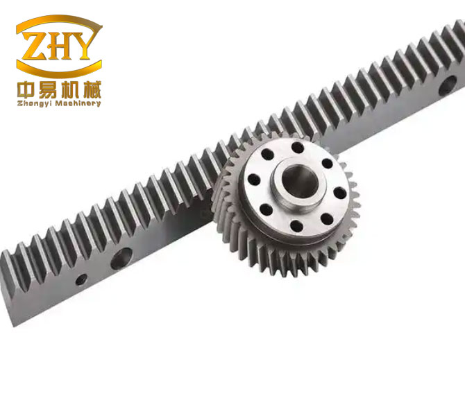
The rack and pinion gear drilling rig replaces the traveling block, draw works, and wire rope with a top-drive unit and a rack and pinion gear mechanism. The rack is fixed to the derrick, while the pinion is connected to the top drive. As the pinion rotates, the top drive moves up and down along the rack. This configuration allows the rig to provide upward force and also to generate downward pressure in shallow sections, greatly improving drilling efficiency. Because the rack and pinion gear system is subjected to heavy loads and harsh working conditions, the rack is designed with a large module, far exceeding conventional parameters. The fastening of the rack to the derrick is therefore a critical design issue. Common fastening methods include welding, bolted connections, and roller-based systems. Bolted connections are preferred because they are easy to disassemble and provide reliable connection. High-strength friction-type bolts are widely used because they generate resistance on the contact surface through preload, improving the integrity and stiffness of the connection without macroscopic slip. However, current design specifications for friction-type high-strength bolted connections mainly rely on the slip coefficient and bolt preload to determine bearing capacity. The complex working conditions of a rack and pinion gear drilling rig, the long length of the fixed parts, the unclear number of bolts, and vibration all affect bolt fastening. Since research on rack and pinion gear drilling rigs started relatively late and is limited in number, there is no clear bolt fastening design scheme in relevant specifications. Designers often refer to existing schemes, which may not match actual working conditions. My research aims to improve the technical level of domestic rack and pinion gear drilling rigs and provide reference for other engineering fields using similar transmission structures.
I reviewed the design methods for multi-bolt connections in domestic and international bolt design standards. I summarized the contact problem analysis methods for bolted connections, the creep analysis theory of materials during bolt tightening, and analyzed the load distribution of multi-bolt connections using linear elastic theory. Considering the calculation accuracy and convergence of creep models, I selected the combined time hardening model to study bolt loosening. I then established a parametric model of rack fastening using CAD methods. Based on the third strength theory and the material strength requirements of the rack and pinion gear, I proposed a method to evaluate the fastening effect of heavy-duty rack multi-bolt connections by using the relative displacement between bolts and bolt holes. I also studied the influence of bolt arrangement parameters, including bolt spacing, end distance, hole diameter, and derrick connection plate thickness, on this relative displacement. The results showed that for heavy-duty rack and pinion gear systems, using 36 mm bolts with a bolt spacing of 200 mm, a larger end distance, and smaller bolt holes and derrick connection plate thickness produces better fastening performance. I analyzed thread load distribution using the Sopwith and Yamamoto methods, established a single-bolt fastening finite element model that includes the thread lead angle, and simulated the thread load distribution. I validated the accuracy of the thread load distribution model against photoelastic experimental data. I studied the influence of thread structural parameters, including the number of engaged threads, minor diameter, pressure angle, pitch, and friction coefficient, on bolt load distribution and residual preload after bolt relaxation. Considering the impact load experienced by the drilling rig under actual working conditions, I investigated the effects of transverse load amplitude, preload, and thread friction coefficient on residual preload. Finally, I designed a rack fastening experiment based on the rack and pinion gear lifting test rig. I tested the strain at the bolt holes of the rack under no-load lifting, automatic drilling feed, high-speed drilling feed, and maximum hook load conditions. The experimental results showed that the multi-bolt fastening scheme can achieve the fastening of the rack and derrick under design conditions. The proposed method of using the relative displacement difference between bolts and bolt holes to evaluate the fastening effect of heavy-duty rack multi-bolt connections is feasible.
In the following sections, I present the theoretical background, the finite element modeling approach, the parametric study of bolt arrangement, the thread load and relaxation analysis, the transverse load loosening study, and the experimental validation. I use many tables and equations to summarize the findings and to make the analysis transparent and reproducible. The term rack and pinion gear appears throughout because the entire study is motivated by the need to ensure reliable fastening in a rack and pinion gear drilling system.
I first examined the bolt preload and bearing capacity calculation methods specified in different standards. The Chinese steel structure design code, the American design specification, and the European design code provide different expressions for the slip resistance of a single friction-type high-strength bolt. These expressions are important because they define the baseline preload that a bolt must achieve to ensure friction-based load transfer in a rack and pinion gear fastening system.
For the Chinese code, the design bearing capacity of a single friction-type high-strength bolt is given by:
$$ N_v^b = 0.9 n_f \mu P $$
where \(n_f\) is the number of friction surfaces, \(\mu\) is the slip coefficient, and \(P\) is the design preload of the friction-type bolt. In the American specification, the design preload under the LRFD system is defined as:
$$ R_n = \mu D_h T_b n_s \phi $$
where \(\mu\) is the slip coefficient, \(T_b\) is the minimum preload of the bolt, \(n_s\) is the number of slip planes, \(D_h\) is a factor typically taken as 1.13, and \(\phi\) is a resistance factor. For the European code, the design bearing resistance of a single bolt in a single-lap joint is limited by:
$$ F_{m2} = \frac{1.5 f_u d t}{r_{m2}} $$
where \(f_u\) is the ultimate tensile strength of the connected part, \(d\) is the bolt diameter, \(t\) is the thickness of the connected part, and \(r_{m2}\) is a material factor. These formulas provided the starting point for my preload selection in the rack and pinion gear fastening design. I summarized the recommended preload values for different bolt grades and diameters in Table 1.
| Bolt grade | Bolt diameter (mm) | Chinese code (kN) | American code (kN) | European code (kN) |
|---|---|---|---|---|
| 8.8 | 16 | 70 | 91 | 88 |
| 8.8 | 20 | 110 | 142 | 137 |
| 8.8 | 24 | 155 | 205 | 198 |
| 8.8 | 30 | 250 | 326 | 314 |
| 8.8 | 36 | 375 | 475 | 416 |
| 10.9 | 16 | 100 | 114 | 110 |
| 10.9 | 20 | 155 | 179 | 172 |
| 10.9 | 24 | 225 | 257 | 247 |
| 10.9 | 30 | 355 | 408 | 393 |
| 10.9 | 36 | 528 | 595 | 520 |
The standards also specify minimum and maximum bolt spacing, edge distance, and end distance. These geometric constraints are critical for the rack and pinion gear fastening because they control the stress distribution around the bolt holes and the overall stiffness of the connection. I summarized the allowable distances in Table 2 based on the Chinese, American, and European specifications.
| Parameter | Chinese code (GB50017) | American code (ANSI/AISC) | European code (Eurocode 3) |
|---|---|---|---|
| Minimum bolt spacing \(p_1\) | 3d | 2.67d (recommended 3d) | 2.2d |
| Maximum bolt spacing \(p_1\) | 16d or 24t (smaller) | 24t or 305 mm | 14t or 200 mm (smaller) |
| Minimum end distance \(e_2\) | 2d | See table for each diameter | 1.2d |
| Maximum end distance \(e_2\) | 4d or 8t (smaller) | 12t and not more than 150 mm | 4t + 40 mm |
| Minimum edge distance \(e_3\) | 1.5d (sheared edge) | 1.75d for >36 mm | 1.2d |
After reviewing the standards, I developed a theoretical model for multi-bolt load distribution. In a multi-bolt connection, the total bearing capacity is not simply the sum of the capacities of individual bolts because the load is not uniformly distributed among the bolts. The elastic interaction between bolts and connected plates causes uneven load sharing. I assumed that the load transfer between bolts depends entirely on the shear force and preload carried by the bolts, and I neglected the influence of plate deformation and the resistance between side plates. I also neglected the contribution of bolt bending after deformation to the joint capacity. When the bolt spacing is wide, I ignored the mutual influence of adjacent bolts, and I considered only the deformation of the overall structure and the bolts caused by the load.
For a joint with a single row of bolts, the sum of the bolt loads equals the external load:
$$ \sum_{i=1}^{n} P_i = F $$
where \(P_i\) is the load carried by the \(i\)-th bolt and \(F\) is the external load. The deformation compatibility between the middle plate and the side plates can be expressed as:
$$ \delta_{i+1} – \delta_i = \Delta_{rp} – \Delta_{rw} $$
where \(\delta_i\) is the bending deformation of the \(i\)-th bolt, \(\Delta_{rp}\) is the tensile deformation of the side plate between bolt \(i\) and bolt \(i+1\), and \(\Delta_{rw}\) is the tensile deformation of the middle plate between the same bolts. The tensile deformations are given by:
$$ \Delta_{rw} = \frac{\beta_w F_w r}{b_w t_w E_w} $$
$$ \Delta_{rp} = \frac{\beta_p F_p r}{b_p t_p E_p} $$
where \(\beta_w\) and \(\beta_p\) are stress concentration coefficients, \(F_w\) and \(F_p\) are the internal forces in the middle and side plates, \(r\) is the bolt spacing, \(b\) and \(t\) are the width and thickness of the plates, and \(E\) is the elastic modulus. Assuming a linear relationship between bolt bending deformation and the load it carries, I obtained the recurrence relation:
$$ P_{i-1} – (1 + K_p + K_w) P_i + P_{i+1} = 0 $$
where \(K_p\) and \(K_w\) are constants that depend on the geometry and material properties of the side and middle plates. This recurrence relation describes how the load is distributed among the bolts in a multi-bolt connection. I used this model to understand the uneven load sharing in the rack and pinion gear fastening system.
I then considered the creep behavior of the bolted joint. Creep is the time-dependent increase in strain under a constant load. It is especially important for bolted connections because the preload can relax over time due to plastic deformation and creep at the contact surfaces. I reviewed several creep theories, including the solid-state equation, the auxiliary variable method, the delay theory, and the combined time hardening model. Among these, the combined time hardening model available in ANSYS provided a good balance between accuracy and convergence. The model is expressed as:
$$ \dot{\varepsilon}_{cr} = c_1 \sigma^{c_2} t^{c_3} e^{-c_4/T} + c_5 \sigma^{c_6} t^{c_7} e^{-c_4/T} $$
where \(c_1\) through \(c_7\) are material constants, \(\sigma\) is stress, \(t\) is time, and \(T\) is absolute temperature. The first term represents primary creep and the second term represents secondary creep. I used this model to simulate the relaxation of the bolt preload in the rack and pinion gear fastening system. The creep parameters for the connected plates and for the bolt and nut are summarized in Table 3.
| Component | \(c_1\) | \(c_2\) | \(c_3\) | \(c_4\) | \(c_5\) | \(c_6\) | \(c_7\) |
|---|---|---|---|---|---|---|---|
| Connected plate | 2.5E-08 | 1.28 | -0.999 | 1935 | 1E-14 | 23.19 | 40000 |
| Bolt and nut | 6.8E-16 | 5 | -0.213 | 1935 | 2.35E-7 | 10.29 | 40000 |
The contact between the bolt head, nut, plates, and threads introduces state nonlinearity. I used the augmented Lagrangian method in ANSYS to solve the contact problem because it provides good convergence and accuracy. I defined friction contacts between the bolt head and the rack, between the nut and the derrick connection plate, and between the rack and the derrick connection plate. The contact settings are listed in Table 4.
| Contact pair | Contact type | Friction coefficient |
|---|---|---|
| Rack and derrick connection plate | Friction | 0.4 |
| Bolt head and rack | Friction | 0.2 |
| Bolt shank and bolt hole | Friction | 0.2 |
| Nut and derrick connection plate | Friction | 0.2 |
| Bolt and nut | Bonded | — |
| Support tube and rack | Bonded | — |
I then developed a parametric model of the rack fastening using SolidWorks and its API. The model included a rack fixed to a derrick connection plate with bolts arranged symmetrically. The bolt diameter was 36 mm, the bolt hole diameter was 37 mm, and the bolts and nuts were standard. The rack material was 40CrNi2Mo, the derrick connection plate was ordinary structural steel, and the bolts and nuts were 30CrMnSi with a property class of 8.8 for the bolt and 9 for the nut. The bolt spacing, end distance, hole diameter, and plate thickness were parameterized. I used a Visual Basic .NET program to control SolidWorks and automatically generate the geometry for different parameter combinations. This allowed me to perform a large number of simulations efficiently. I used HyperMesh to generate a high-quality mesh with hexahedral elements, and I refined the mesh around the bolt holes to capture stress concentrations. The finite element model used SOLID185 elements, and the contact behavior was modeled with the augmented Lagrangian method. The boundary conditions were applied in three steps: first, the derrick connection plate was constrained in all directions; second, a preload of 469 kN was applied to each bolt; third, a working load of 625 kN was applied to the rack tooth in the Y direction. I considered six meshing positions along the rack to simulate the movement of the pinion.
To evaluate the fastening effect, I proposed a criterion based on the relative displacement between the bolt and the bolt hole. The standard deviation of these relative displacements was used as an indicator of fastening quality. A smaller standard deviation means that the bolts share the load more evenly, which indicates better fastening performance. The standard deviation is calculated as:
$$ S = \sqrt{\frac{1}{n-1} \sum_{i=1}^{n} (d_i – \bar{d})^2} $$
where \(d_i\) is the relative displacement between the \(i\)-th bolt and its corresponding bolt hole, \(\bar{d}\) is the average relative displacement, and \(n\) is the number of bolts. I then performed a parametric study to investigate how bolt spacing, end distance, hole diameter, and plate thickness affect the standard deviation. The results are summarized in Table 5.
| Parameter | Range studied | Effect on standard deviation | Optimal value or trend |
|---|---|---|---|
| Bolt spacing \(P\) | 100, 150, 200, 250, 300 mm | Standard deviation is minimum at 200 mm | 200 mm gives the best fastening effect |
| End distance \(e\) | 1.5d, 2d, 2.5d, 3d, 3.5d | Standard deviation decreases as end distance increases | Larger end distance improves fastening |
| Hole diameter \(D\) | 37, 38, 39, 40, 41 mm | Standard deviation increases as hole diameter increases | Standard hole (37 mm) is best |
| Plate thickness \(t\) | 16, 20, 25, 30, 35 mm | Standard deviation increases as plate thickness increases | Thinner plate gives better fastening effect |
The results showed that for a heavy-duty rack and pinion gear system, the bolt spacing should be 200 mm, the end distance should be as large as practical, and the bolt hole and derrick connection plate thickness should be as small as possible while still meeting strength requirements. This finding is important because it provides a clear guideline for designing the fastening of a rack and pinion gear in a drilling rig.
Next, I investigated the thread load distribution and its effect on preload relaxation. I used the Sopwith and Yamamoto methods to analytically describe the load distribution along the engaged threads. In the Sopwith method, the thread is treated as a simply supported beam, and the axial load distribution \(p(x)\) is given by:
$$ p(x) = \frac{F \gamma \cosh(\gamma x)}{\sinh(\gamma L)} $$
where \(F\) is the total axial load, \(\gamma\) is a stiffness parameter, and \(L\) is the engagement length. The axial force in the bolt is:
$$ Q(x) = \frac{F \sinh(\gamma x)}{\sinh(\gamma L)} $$
In the Yamamoto method, the thread is treated as a cantilever beam, and the load distribution is expressed as:
$$ F(x) = \frac{F \sinh(\lambda x)}{\sinh(\lambda L)} $$
where \(\lambda\) is a parameter that depends on the elastic deformation of the thread and the bolt and nut bodies. I validated these analytical models against a finite element model that included the thread lead angle and against photoelastic experimental data. The comparison showed good agreement. The first engaged thread carried about 36.4% of the load in the finite element model, 32.4% in the Sopwith model, 28.6% in the Yamamoto model, and 32.5% in the photoelastic experiment. The first three threads carried more than 60% of the total load in all cases, while the later threads carried very little. This confirms that the load is highly concentrated on the first few threads.
I then studied how thread parameters affect the load distribution. The parameters included the number of engaged threads, friction coefficient, pressure angle, minor diameter, and pitch. The results are summarized in Table 6.
| Thread parameter | Range studied | Effect on load distribution | Effect on preload relaxation |
|---|---|---|---|
| Number of engaged threads | 5, 7, 9, 12, 15 | Increasing the number reduces the maximum load and makes distribution more uniform; variance decreases exponentially | Increasing the number reduces the change in preload from 5730 N to 650 N |
| Friction coefficient | 0.1, 0.15, 0.2, 0.25, 0.3 | Small effect on load distribution | Small effect on preload relaxation; change from 800 N to 762 N |
| Pressure angle | 58.5°, 60°, 61.5°, 63°, 64.5° | Increasing pressure angle slightly increases first thread load; maximum difference 1.76% | Increasing pressure angle increases creep and preload relaxation from 752 N to 833 N |
| Minor diameter | 16.918, 17.018, 17.118, 17.218, 17.318 mm | Very small effect on load distribution; maximum difference 0.47% | Increasing minor diameter reduces preload relaxation from 776 N to 674 N |
| Pitch | 2, 2.5, 3, 3.5, 4 mm | Increasing pitch increases first thread load; maximum difference 4.67%; variance increases exponentially | Increasing pitch increases creep and preload relaxation from 780 N to 1120 N |
These results show that increasing the number of engaged threads and the friction coefficient improves load sharing and reduces relaxation. On the other hand, increasing the pressure angle, minor diameter, or pitch tends to concentrate the load and increase relaxation. Therefore, a well-designed thread structure can significantly improve the anti-loosening performance of a rack and pinion gear fastening system.
I also studied the effect of transverse load on bolt loosening. Under transverse cyclic loading, the bolt can lose preload and eventually loosen. I used the finite element model to simulate this process. The transverse load was applied as a triangular wave, and the preload was monitored over time. I investigated the effects of initial preload, load amplitude, and thread friction coefficient. The results are summarized in Table 7.
| Parameter | Range studied | Effect on preload loss | Trend |
|---|---|---|---|
| Initial preload | 400, 420, 450, 469, 500 kN | Higher initial preload leads to faster absolute preload loss but a smaller percentage loss | Lower initial preload makes the bolt less likely to loosen, but higher preload increases contact stress and friction |
| Transverse load amplitude | 0.2, 0.3, 0.4, 0.5, 0.6 mm | Larger amplitude causes faster and greater preload loss | Larger amplitude makes loosening more likely |
| Thread friction coefficient | 0.1, 0.15, 0.3 | Lower friction coefficient causes faster preload loss | Higher friction coefficient reduces loosening but increases thread root stress and wear |
The transverse load analysis showed that the loosening process occurs in two stages: an initial rapid drop in preload due to plastic deformation and a later slower drop due to micro-wear. Increasing the initial preload can increase the contact stress and friction between the threads, which delays loosening, but it also increases the risk of plastic deformation. Therefore, a balance must be struck between preload and anti-loosening performance.
Finally, I validated my numerical and theoretical findings with experiments on a rack and pinion gear lifting test rig. The test rig included a rack and pinion gear transmission system, a data acquisition system, and strain gauges. I attached strain gauges to the rack at the top, middle, and bottom of the tooth side, and at each bolt hole. I measured the strain in two directions at each point. The loads were applied by hydraulic cylinders at pressures of 4, 6, 8, and 10 MPa, corresponding to hook loads of 100, 150, 200, and 250 tons. I recorded the strain data for 10 seconds at each load and repeated each measurement three times. The maximum stress in the rack increased with the load, and all stresses remained below the allowable stress of the material. The experimental results were compared with the finite element simulation results, and the maximum error was within 5%. This validated the reliability of the finite element model. The strain at the bolt holes increased linearly with the hook load, which confirmed that the bolted connection behaved elastically under the tested conditions. The experimental loads, measured stresses, and simulation results are summarized in Table 8.
| Hydraulic pressure (MPa) | Hook load (tons) | Measured maximum stress (MPa) | Simulated maximum stress (MPa) | Error (%) |
|---|---|---|---|---|
| 4 | 100 | 152 | 147 | 3.4 |
| 6 | 150 | 228 | 220 | 3.6 |
| 8 | 200 | 304 | 293 | 3.8 |
| 10 | 250 | 380 | 365 | 4.1 |
The experimental validation confirmed that the multi-bolt fastening scheme can reliably fix the rack to the derrick under design conditions. The proposed method of using the relative displacement difference between bolts and bolt holes to evaluate the fastening effect of heavy-duty rack multi-bolt connections is feasible. The results also showed that the finite element model is accurate and can be used for further optimization of the rack and pinion gear fastening system.
In conclusion, I studied the bolt fastening and anti-loosening behavior of a rack and pinion gear drilling system. I reviewed international bolt design standards and developed a multi-bolt load distribution model. I used a combined time hardening creep model to simulate preload relaxation. I performed parametric studies on bolt spacing, end distance, hole diameter, and plate thickness, and I found that a bolt spacing of 200 mm, a larger end distance, and smaller hole diameter and plate thickness improve the fastening effect. I analyzed thread load distribution and found that increasing the number of engaged threads and the friction coefficient improves load sharing and reduces relaxation, while increasing pressure angle, minor diameter, or pitch has the opposite effect. I studied transverse load loosening and found that higher initial preload, smaller load amplitude, and higher friction coefficient reduce the loosening rate. Finally, I validated the numerical models with experiments on a rack and pinion gear lifting test rig, achieving an error of less than 5%. The findings provide a scientific basis for the design of bolt fastening in heavy-duty rack and pinion gear drilling systems and can be extended to other engineering applications using similar transmission structures.
For future work, I suggest investigating the effect of the rack load position on bolt fastening under different hook loads through additional field experiments. I also recommend studying the safety of the rack and pinion gear fastening system when some bolts fail, by simulating bolt failure on the test rig. These studies would further improve the reliability and safety of rack and pinion gear drilling systems.