
High-speed railway transportation has become one of the most important modes of passenger and freight movement because of its high speed and large carrying capacity. The rail itself is the foundation of safe and stable high-speed operation. To meet the stringent requirements of modern high-speed trains, the railway industry has adopted the use of one-hundred-meter fixed-length heavy rails. The lifting and handling of these long heavy rails is a critical step in rail production, storage, and stacking. The stability and accuracy of the lifting process directly influence rail deformation, surface damage, and the safety of storage and stacking operations.
Traditional lifting of one-hundred-meter heavy rails relies on wire rope drum systems with multiple lifting points. Although such systems are widely used, they suffer from several inherent drawbacks. The synchronization in the vertical direction is difficult to control, which leads to uneven load distribution among lifting points. The flexibility of the wire rope causes significant lateral swinging, which can induce torsion and uneven stress in the rail. Outdoor operation makes the system sensitive to wind-induced oscillation. These problems reduce the quality of rail handling and increase the risk of surface damage and structural deformation.
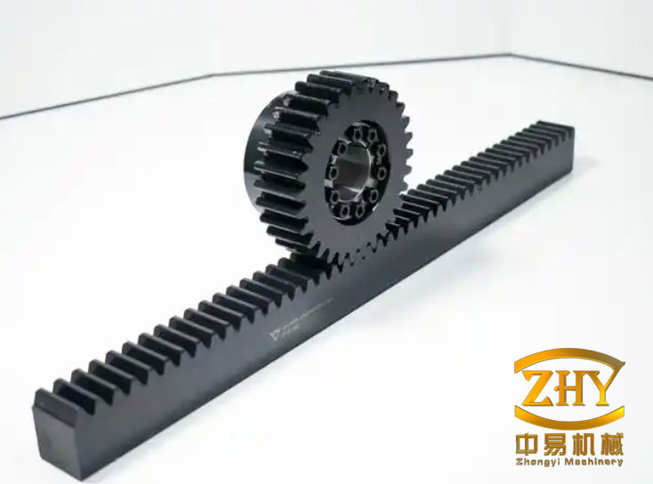
To overcome these limitations, I proposed a new lifting scheme based on a rack and pinion gear transmission. Compared with wire rope drum systems, a rack and pinion gear drive offers high power transmission, high efficiency, precise and controllable lifting distance, high stiffness, and inherent anti-swing behavior. The rack and pinion gear mechanism also has a long service life and stable operation, which makes it suitable for heavy-duty and high-precision lifting tasks. However, during the virtual assembly of the initial rack and pinion gear transmission model, I observed a serious tooth interference problem. The gears and the rack could not be assembled correctly. This interference problem is the central focus of my research.
Design Requirements and Load Analysis
The lifting system is designed for a group of seven heavy rails, with a total mass of 7.6 tons per lifting point. The entire lifting mechanism has 16 lifting points spaced 6 meters apart. Each lifting point uses an electromagnetic chuck. The lifting speed is low, approximately 5 m/min, and the guide system uses V-shaped rollers to ensure stable motion in both longitudinal and lateral directions. The basic design data are summarized in Table 1.
| Parameter | Value |
|---|---|
| Number of rails per group | 7 |
| Load per lifting point | 7.6 t |
| Number of lifting points | 16 |
| Distance between lifting points | 6 m |
| Lifting speed | 5 m/min |
| Gear speed | 7.76 r/min |
| Module | 10 mm |
| Pressure angle | 20° |
| Gear material | 40Cr, quenched and tempered, surface hardness 48–55 HRC |
| Rack material | 45 steel, tempered, hardness 240 HB |
| Accuracy grade | 7 (GB10095-88) |
The torque required for each gear is calculated from the load and the pitch diameter. For the initial design with two gears meshing with a single rack, the torque per gear is:
$$T_1 = \frac{G d}{2} = \frac{38000 \times 200}{2} = 3.8 \times 10^6 \ \text{N}\cdot\text{mm}$$
where \(G = 38000\) N is the load per gear and \(d = 200\) mm is the pitch diameter. The bending strength and contact strength are checked according to standard mechanical design formulas. The module selection is based on the bending strength:
$$m_n \geq \sqrt[3]{\frac{12.4 K T_1 Y_{Fa}}{\phi_d z_1^2 \sigma_F}}$$
where \(K\) is the load factor, \(Y_{Fa}\) is the tooth form factor, \(\phi_d\) is the face width coefficient, \(z_1\) is the number of teeth, and \(\sigma_F\) is the allowable bending stress. For the initial two-gear scheme, the calculated module is 6.062 mm, and a module of 10 mm is selected. The contact fatigue strength is checked as:
$$\sigma_H = Z_H Z_E Z_\varepsilon \sqrt{\frac{2 K T_1 (u+1)}{d_1^3 \phi_d u}} \leq [\sigma_H]$$
For the two-gear scheme, the calculated contact stress is 815.52 MPa, which is very close to the allowable stress of 843.75 MPa. Because the application is a heavy-duty lifting mechanism, the reliability margin is insufficient. Therefore, I abandoned the two-gear single-rack scheme and adopted a four-gear single-rack scheme.
| Scheme | Calculated contact stress (MPa) | Allowable contact stress (MPa) | Result |
|---|---|---|---|
| Two gears meshing with one rack | 815.52 | 843.75 | Insufficient margin |
| Four gears meshing with one rack | 576.66 | 928.125 | Satisfactory |
For the four-gear scheme, the load per gear is half of the original value, and the contact stress decreases substantially. The calculated stress is 576.66 MPa, which is well below the allowable stress. Therefore, the four-gear single-rack configuration is selected. To reduce the number of drive motors and simplify the mechanical structure, I designed a single-motor drive that uses a worm gear to drive two intermediate pinions, which in turn drive four large gears on both sides of the rack. This configuration is called the single-drive multi-point meshing rack and pinion gear transmission.
Interference Problem in Multi-Point Meshing
After the single-drive multi-point meshing rack and pinion gear transmission scheme was determined, I used standard involute spur gears and a standard rack for virtual assembly. The gears and rack could not be assembled correctly, and tooth interference was observed. I tested several other combinations of gear teeth numbers, and the interference always existed. Tooth interference occurs when the envelope of one gear enters the profile of another gear. In a rack and pinion gear system, interference can cause impact, impossible assembly, and tooth breakage. Therefore, solving the interference problem is essential.
To analyze the interference, I established a systematic method to calculate the interference amount. The basic idea is to accumulate the interference from the gear–gear meshing pairs to the final gear–rack meshing position. The model consists of three gears and one rack. Gear 1 meshes with the rack, gear 1 meshes with gear 2, gear 2 meshes with gear 3, and gear 3 meshes with the rack. The interference is accumulated at the last meshing pair between gear 3 and the rack.
Coordinate System and Interference Amount Calculation
I defined several coordinate systems to describe the positions and meshing lines. The first coordinate system, system 0, has its origin at the center of gear 1, with the Y-axis along the line connecting the gear centers and the X-axis perpendicular to it. The base circle equations of gear 1 and gear 2 are:
$$(x – a_1)^2 + (y – b_1)^2 = r_{b1}^2$$
$$(x – a_2)^2 + (y – b_2)^2 = r_{b2}^2$$
The internal common tangent line of the two base circles is given by:
$$y = k_1 x + p_1$$
where the slope and intercept are determined from the condition that the distances from the base circle centers to the tangent line equal the base circle radii. Solving these equations gives the tangent line equation in system 0.
Then I rotated the coordinate system to align the Y-axis with the intersection of the involute and the base circle. The rotation angle \(\delta_1\) is determined by the tooth thickness and tooth pitch on the base circle. The base circle tooth thickness is:
$$s_{b1} = s_1 \cos\alpha + d_1 \cos\alpha \, \text{inv}\alpha$$
$$s_1 = \frac{\pi m}{2} + 2 x m \tan\alpha$$
where \(x\) is the modification coefficient. The rotation angle \(\delta_1\) is calculated from the number of teeth and the arc lengths. After rotation, the tangent line equation becomes:
$$y = \frac{k_1 + \tan\delta_1}{1 – k_1 \tan\delta_1} x + \frac{p_1}{\cos\delta_1 – k_1 \sin\delta_1}$$
The involute equation of gear 1 is:
$$x = r_{b1} \sin u_k – r_{b1} u_k \cos u_k$$
$$y = r_{b1} \cos u_k + r_{b1} u_k \sin u_k$$
where \(u_k = \alpha_k + \theta_k\) is the parameter. The range of \(u_k\) is from 0 to \(\alpha_a + \theta_a\), where \(\alpha_a\) is the pressure angle at the addendum circle and \(\theta_a\) is the corresponding involute function value. The intersection point P of the tangent line and the involute is found by solving the combined equations. I used a numerical interpolation method with a computer program to solve for \(u_k\).
Similar procedures are applied to the meshing between gear 2 and gear 3, and between gear 3 and the rack. The coordinate transformations involve rotations and translations. The final interference amount is defined as the distance between two points M and N in the local coordinate system of the final gear–rack mesh. The points M and N are the intersection of the tangent line with the rack tooth profile and the actual meshing point on the gear involute. The interference amount is:
$$\Delta = \sqrt{(x_M – x_N)^2 + (y_M – y_N)^2} \cos\gamma$$
where \(\gamma\) is the angle between the line MN and the direction of the interference. A complete calculation flow was developed and implemented in a computer program.
Example Calculation of Interference Amount
For the actual parameters of my design, the gears have \(z_1 = z_3 = 25\), \(z_2 = 18\), module \(m = 10\), and pressure angle \(\alpha = 20^\circ\). The rack parameters are determined by the gears. The calculated interference amount is 3.59 mm. The detailed calculation steps are summarized in Table 3.
| Parameter | Value |
|---|---|
| Number of teeth of gear 1 | 25 |
| Number of teeth of gear 2 | 18 |
| Number of teeth of gear 3 | 25 |
| Module | 10 mm |
| Pressure angle | 20° |
| Base circle tooth thickness of gear 1 | 18.26199376 mm |
| Base circle tooth thickness of gear 2 | 17.28163085 mm |
| Rotation angle for gear 1 | 8.907893026° |
| Rotation angle for gear 2 | 11.70790071° |
| Meshing angle for gear 1–2 | 9.236° |
| Meshing angle for gear 2–3 | 8° |
| Meshing angle for gear 3–rack | 5.30789303° |
| Final interference amount | 3.59 mm |
The interference amount of 3.59 mm is significant and cannot be ignored. This confirms that the standard gear design cannot be assembled correctly in the multi-point meshing configuration.
Displacement Coefficient Method
The interference amount is directly related to the center distance. If the center distance can be slightly adjusted, the interference can be eliminated. Gear modification, also known as profile shifting, changes the center distance without affecting the operation of the mechanism. I developed a method called the displacement coefficient method to solve the interference problem. The principle is to adjust the modification coefficients of the gears so that the actual center distance matches the required center distance and the interference is eliminated.
The standard center distance of a gear pair is:
$$a = \frac{m(z_1 + z_2)}{2}$$
The actual center distance after considering the interference amount is:
$$a’ = a – \frac{\Delta}{2}$$
For the gear pair with \(z_1 = 25\) and \(z_2 = 18\), the standard center distance is 215 mm. The interference amount is 3.59 mm, so the actual center distance is approximately 213 mm. The working pressure angle \(\alpha’\) is calculated from:
$$\alpha’ = \arccos\left(\frac{a}{a’} \cos\alpha\right)$$
Substituting the values gives \(\alpha’ = 19.25092324^\circ\). The sum of the modification coefficients \(x_\Sigma\) is determined from the no-backlash meshing equation:
$$\text{inv}\alpha’ = \text{inv}\alpha + \frac{2 \tan\alpha}{z_1 + z_2} x_\Sigma$$
where \(\text{inv}\alpha = \tan\alpha – \alpha\). Using the line graph method for modification coefficient selection, I determined the total modification coefficient \(x_\Sigma = -0.1926\). The modification coefficients are then distributed between the small gear and the large gear. The gear ratio is \(u = z_2 / z_1 = 18 / 25 = 0.72\). From the line graph, the small gear modification coefficient is \(x_1 = 0.03\), and the large gear modification coefficient is \(x_2 = x_\Sigma – x_1 = -0.2226\).
The minimum modification coefficient to avoid undercut is:
$$x_{\min} = h_a^* – \frac{z \sin^2\alpha}{2}$$
For the small gear, \(x_{\min} = -0.0528\), and for the large gear, \(x_{\min} = -0.4622\). The selected modification coefficients are larger than these minimum values, so no undercut occurs. The modification coefficients are summarized in Table 4.
| Parameter | Small gear (z = 18) | Large gear (z = 25) |
|---|---|---|
| Modification coefficient | 0.03 | -0.2226 |
| Minimum modification coefficient | -0.0528 | -0.4622 |
| Undercut condition | Safe | Safe |
The displacement coefficient method effectively solves the interference problem by slightly adjusting the center distance and redistributing the modification coefficients. The gears can then be assembled correctly, and the load distribution becomes more uniform.
Three-Dimensional Modeling and Finite Element Simulation
I used CAXA and SolidWorks to create the three-dimensional models of the modified gears and rack. The gear parameters are shown in Table 5. The modification coefficients were applied to the gear profiles. The models were then assembled in SolidWorks with the correct center distances and meshing positions.
| Parameter | Value |
|---|---|
| Module | 10 mm |
| Number of teeth of small gear | 18 |
| Number of teeth of large gear | 25 |
| Face width | 40 mm |
| Pressure angle | 20° |
| Small gear modification coefficient | 0.03 |
| Large gear modification coefficient | -0.2226 |
| Elastic modulus | 211 GPa |
| Poisson’s ratio | 0.3 |
| Density | 7820 kg/m³ |
After assembly, I compared the interference before and after modification. The unmodified model showed clear interference, while the modified model assembled correctly without any interference. I then performed finite element simulation using Abaqus/Explicit. The material properties were assigned as given in Table 5. A dynamic explicit analysis step was created. Surface-to-surface contact was defined between the meshing pairs. The mesh was refined in the contact regions. The boundary conditions included a rotational velocity on the driving pinion and a torque on the output gear to simulate the load.
The load torque for the simulation is calculated as:
$$T = \frac{G d}{2} = \frac{7800 \times 9.8 \times 10}{2} = 4777500 \ \text{N}\cdot\text{mm}$$
The simulation results show that the maximum contact stress on the tooth surface is 802 MPa. The allowable contact stress for the gear material is 928.125 MPa. Therefore, the modified gears satisfy the strength requirement. The stress distribution is uniform, and no interference occurs. The simulation results are summarized in Table 6.
| Parameter | Value |
|---|---|
| Maximum contact stress | 802 MPa |
| Allowable contact stress | 928.125 MPa |
| Interference | None |
| Load distribution | Uniform |
Based on the displacement coefficient method, I completed the detailed structural design of the single-drive multi-point meshing rack and pinion gear lifting mechanism and manufactured a prototype. The prototype was tested, and the results showed flexible operation, uniform tooth loading, and low heat generation. These results further verify that the displacement coefficient method can effectively solve the interference problem in single-drive multi-point meshing rack and pinion gear transmission mechanisms.
Conclusion
I proposed a single-drive multi-point meshing rack and pinion gear transmission scheme for lifting one-hundred-meter heavy rails. The scheme replaces the traditional wire rope drum system and offers precise lifting distance, high stiffness, and anti-swing behavior. Strength calculations showed that a two-gear single-rack scheme has insufficient load capacity, while a four-gear single-rack scheme satisfies the requirements. I designed a single-motor drive using a worm gear to drive two intermediate pinions, which then drive four large gears.
During virtual assembly, I discovered a serious tooth interference problem. I developed a systematic method to calculate the interference amount by accumulating the interference from gear–gear meshing pairs to the final gear–rack meshing position. The interference amount for the actual design parameters was 3.59 mm. I then proposed the displacement coefficient method to solve the interference problem by adjusting the modification coefficients and the center distance. The total modification coefficient was determined as \(-0.1926\), with \(x_1 = 0.03\) and \(x_2 = -0.2226\). The modified gears avoid undercut and can be assembled correctly.
Finite element simulation showed that the maximum contact stress after modification is 802 MPa, which is below the allowable stress. The prototype was manufactured and tested, confirming that the interference is eliminated, the load is uniformly distributed, and the mechanism operates reliably. The displacement coefficient method is a practical and effective solution for interference problems in multi-point meshing rack and pinion gear transmissions.
Future Work
The current study focused on a specific heavy rail lifting application. The open-type rack and pinion gear transmission requires proper lubrication, which was not addressed in detail. Future work should consider lubrication design and maintenance. The analytical calculation of interference has some numerical limitations, and more accurate methods should be developed. The selection of modification coefficients was based on center distance control; however, optimizing the modification coefficients for maximum gear strength could further improve performance. The trade-off between center distance and gear strength should be studied more thoroughly.
Three-dimensional modeling and simulation simplified some real-world conditions, and the results may differ from actual operation. More extensive studies on different gear and rack configurations are needed to establish a complete design standard. The single-drive multi-point meshing rack and pinion gear transmission has great potential for replacing traditional wire rope drum systems, but further research and optimization are required before widespread industrial application.