
In this article, I study a new type of energy dissipation device that combines a rack and pinion gear transmission with eddy current damping. I refer to this device as an eddy current damping-rack and gear damper, or ECD-RGD. My main purpose is to explain how the rack and pinion gear mechanism transforms structural motion into rotational motion, how the eddy current damping unit produces a controllable damping force, and how the apparent mass and damping properties interact. I also design a reduced-scale prototype, perform finite element simulations, and conduct experimental tests at different loading angles. The results help me evaluate whether the rack and pinion gear concept can be used in practical vibration control systems.
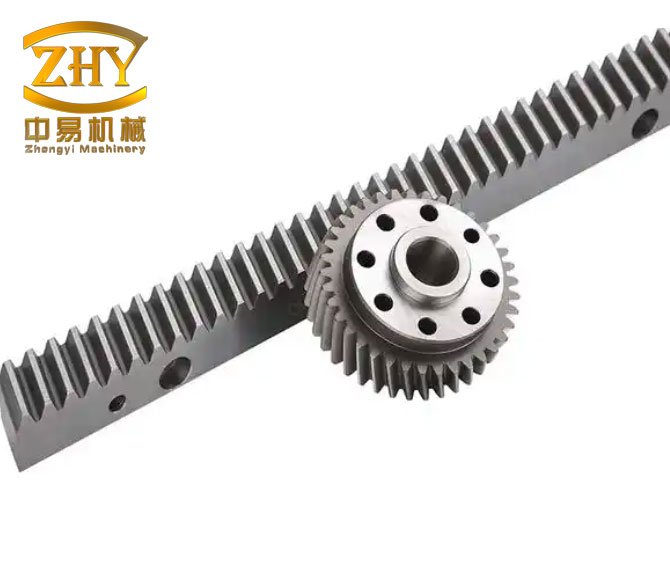
The rack and pinion gear mechanism is central to the device. A rack and pinion gear pair converts linear motion into rotary motion or rotary motion into linear motion. In my damper, the rack is connected to the vibrating structure, and the pinion is connected to a transmission shaft. When the structure moves, the rack drives the pinion, and the pinion drives a multistage gear train. This multistage transmission amplifies angular velocity and angular acceleration. The amplified rotation is then transferred to a conductor plate and a back iron, which rotate inside a magnetic field produced by permanent magnets. The relative motion between the conductor plate and the magnets generates eddy currents, and these eddy currents produce a damping torque that opposes rotation. In this way, the rack and pinion gear system allows a compact linear damper to achieve a large apparent mass and a strong eddy current damping force.
I construct the ECD-RGD from two main subsystems. The first subsystem is a displacement transmission system. It contains a rack, a pinion, a transmission shaft, bearings, a slide rail, a slider, and a base plate. The rack and the slide rail are arranged perpendicularly. The rack meshes with the first pinion gear. The first pinion gear and the second gear are coaxial. The second gear meshes with the third gear. The third gear is coaxial with the conductor plate and the back iron. The second subsystem is the eddy current damping and energy dissipation system. It contains permanent magnets, a conductor plate, and a back iron. When the structure vibrates, the rack moves along its axis, and the rack and pinion gear train converts this linear movement into rotation of the conductor plate. The rotation speed and angular acceleration can be increased by selecting the gear radii appropriately.
I decompose the random vibration direction of a structure into two fixed perpendicular directions. This decomposition is important because the motion direction of a building or bridge during an earthquake or wind event is not known in advance. If a damper has only one working axis, a large angle between the structural motion and the damper axis can reduce its efficiency and may even cause locking. With the rack and pinion gear arrangement, the structural motion is resolved into a rack-axis direction and a slide-rail direction. The rack-axis direction drives the rack and pinion gear transmission and produces the control force. The slide-rail direction does not produce a control force in the same device. Therefore, in practical applications, I recommend installing ECD-RGD units in both perpendicular directions so that the random motion direction can be controlled in two fixed directions. The rack and pinion gear concept therefore provides a clear motion decomposition strategy.
Let me define the main variables used in the theoretical derivation. I use the following notation throughout this article.
| Symbol | Meaning | Unit |
|---|---|---|
| $$u$$ | Displacement of the structure along the excitation direction | m |
| $$\dot{u}$$ | Velocity of the structure along the excitation direction | m/s |
| $$\ddot{u}$$ | Acceleration of the structure along the excitation direction | m/s$$^2$$ |
| $$\alpha$$ | Angle between the structural motion direction and the rack axis | rad or degree |
| $$V$$ | Velocity along the rack axis | m/s |
| $$\theta$$ | Rotation angle of the conductor plate and back iron | rad |
| $$\dot{\theta}$$ | Angular velocity of the conductor plate and back iron | rad/s |
| $$\ddot{\theta}$$ | Angular acceleration of the conductor plate and back iron | rad/s$$^2$$ |
| $$r_1$$ | Radius of the first pinion gear | m |
| $$r_2$$ | Radius of the second gear | m |
| $$r_3$$ | Radius of the third gear | m |
| $$J$$ | Total rotational inertia of rotating components | kg·m$$^2$$ |
| $$T_e$$ | Eddy current damping torque | N·m |
| $$T_s$$ | Total torque at the transmission shaft | N·m |
| $$F$$ | Control force along the structural motion direction | N |
| $$m_c$$ | Total physical mass of the conductor plate and back iron | kg |
| $$R$$ | Outer radius of the conductor plate and back iron | m |
| $$r$$ | Inner radius of the conductor plate and back iron | m |
| $$m_e$$ | Apparent mass of the ECD-RGD | kg |
| $$c_e$$ | Equivalent damping coefficient | N·s/m |
| $$f_0$$ | Internal mechanical friction force | N |
| $$A$$ | Displacement amplitude in harmonic loading | m |
| $$f$$ | Excitation frequency | Hz |
I now derive the relationship between the structural motion and the rack and pinion gear motion. If the structural velocity along the excitation direction is $$\dot{u}$$ and the angle between the structural motion direction and the rack axis is $$\alpha$$, then the rack-axis velocity is
$$ V = \dot{u}\cos\alpha . $$
The angular velocity of the conductor plate and back iron is related to the rack velocity through the gear radii. For the rack and pinion gear train shown in my design, the angular velocity is
$$ \dot{\theta} = \frac{r_2}{r_1 r_3}\dot{u}\cos\alpha . $$
This equation shows that the rack and pinion gear transmission introduces a speed amplification factor. If I define the transmission ratio as
$$ k_g = \frac{r_2}{r_1 r_3} , $$
then the angular velocity can be written more compactly as
$$ \dot{\theta} = k_g \dot{u}\cos\alpha . $$
The angular acceleration is obtained by differentiating the angular velocity with respect to time:
$$ \ddot{\theta} = k_g \ddot{u}\cos\alpha . $$
The rotating conductor plate and back iron have a total rotational inertia $$J$$. The total torque acting on the rotating parts is the sum of the inertial torque and the eddy current damping torque:
$$ T_s = J\ddot{\theta} + T_e(\dot{\theta}) . $$
I assume that the input power and output power of the transmission are equal, apart from friction losses. Therefore,
$$ F\dot{u} = T_s\dot{\theta} . $$
Substituting the expressions for $$\dot{\theta}$$, $$\ddot{\theta}$$, and $$T_s$$ into the power balance equation gives the control force in the structural motion direction:
$$ F = J\left(\frac{r_2}{r_1 r_3}\cos\alpha\right)^2\ddot{u} + T_e(\dot{\theta})\frac{r_2}{r_1 r_3}\cos\alpha . $$
This expression has two parts. The first part is proportional to the structural acceleration and is caused by the rotational inertia of the conductor plate and back iron. The second part is caused by the eddy current damping torque and depends on the angular velocity. Therefore, the rack and pinion gear damper produces an apparent mass inertial force and an eddy current damping force in parallel.
For a solid annular conductor plate and back iron, the total rotational inertia is
$$ J = \frac{1}{2}m_c\left(R^2 + r^2\right) , $$
where $$m_c$$ is the total physical mass of the conductor plate and back iron, $$R$$ is the outer radius, and $$r$$ is the inner radius. Substituting this expression into the control force equation gives
$$ F = m_e \ddot{u} + c_e \dot{u} , $$
where the apparent mass $$m_e$$ and the equivalent damping coefficient $$c_e$$ are
$$ m_e = \frac{1}{2}m_c\left(R^2 + r^2\right)\left(\frac{r_2}{r_1 r_3}\cos\alpha\right)^2 , $$
$$ c_e = \frac{T_e(\dot{\theta})}{\dot{u}}\frac{r_2}{r_1 r_3}\cos\alpha . $$
If the eddy current damping torque is approximately linear with respect to angular velocity, then
$$ T_e(\dot{\theta}) = c_\theta \dot{\theta} , $$
where $$c_\theta$$ is the rotational eddy current damping coefficient. In that case, the equivalent linear damping coefficient becomes
$$ c_e = c_\theta \left(\frac{r_2}{r_1 r_3}\cos\alpha\right)^2 . $$
I also include the internal mechanical friction force in the complete force expression:
$$ F = m_e \ddot{u} + c_e \dot{u} + f_0 \operatorname{sign}(\dot{u}) . $$
This equation is the mechanical model of the ECD-RGD that I use to interpret my experiments. The model shows that the rack and pinion gear damper can be represented as a parallel combination of an apparent mass element and a viscous damping element, with a small friction term.
I designed and manufactured a reduced-scale prototype to study the mechanical properties of the ECD-RGD. The geometric and material parameters of the prototype are listed in the following table.
| Component | Parameter | Value |
|---|---|---|
| First pinion gear | Radius $$r_1$$ | 32 mm |
| Second gear | Radius $$r_2$$ | 96 mm |
| Third gear | Radius $$r_3$$ | 16 mm |
| Conductor plate and back iron | Outer radius $$R$$ | 100 mm |
| Conductor plate and back iron | Inner radius $$r$$ | 10 mm |
| Permanent magnet | Dimensions | 30 mm × 30 mm × 10 mm |
| Permanent magnet | Magnetization direction | 10 mm thickness direction |
| Permanent magnet | Number per side plate | Two pairs |
| Conductor plate | Material | Copper |
| Conductor plate | Thickness | 2 mm |
| Back iron | Thickness | 8 mm |
| Air gap | Between conductor plate and magnet | 4 mm |
| Magnet center | Distance from transmission shaft | 80 mm |
| Rotating mass | Conductor plate and back iron mass $$m_c$$ | 4.89 kg |
The experimental loading device applies harmonic displacement to the rack. I measure the actual displacement with a laser displacement sensor. I place a force sensor between the loading device and the rack to measure the control force produced by the ECD-RGD. The base plate of the damper is fixed to the ground. When the loading device performs harmonic motion, the displacement, velocity, and acceleration can be written as
$$ u = A\sin(2\pi f t) , $$
$$ \dot{u} = 2\pi f A\cos(2\pi f t) , $$
$$ \ddot{u} = -4\pi^2 f^2 A\sin(2\pi f t) . $$
Substituting these expressions into the complete force equation gives
$$ F = -4m_e\pi^2 f^2 A\sin(2\pi f t) + 2c_e\pi f A\cos(2\pi f t) + f_0\operatorname{sign}(\dot{u}) . $$
When the permanent magnets are not installed, the eddy current damping force is absent. The maximum force measured in this condition is denoted by $$F_{a1}$$. The inertial force amplitude is then
$$ Q_{ia} = F_{a1} – f_0\operatorname{sign}(\dot{u}) = 4m_e\pi^2 f^2 A . $$
When the permanent magnets are installed, the maximum force measured is denoted by $$F_{a2}$$. The eddy current damping force amplitude is obtained by subtracting the inertial contribution:
$$ Q_{da} = \sqrt{\left(F_{a2} – f_0\operatorname{sign}(\dot{u})\right)^2 – Q_{ia}^2} = 2c_e\pi f A . $$
I consider two loading angles: $$\alpha = 0^\circ$$ and $$\alpha = 45^\circ$$. These two cases represent the most favorable and the most unfavorable single-device control angles for a single rack and pinion gear damper. A quasi-static test shows that the friction force is 35 N when $$\alpha = 0^\circ$$ and 55 N when $$\alpha = 45^\circ$$. The test frequency range is from 0.10 Hz to 0.48 Hz, and the single-side displacement amplitude is 50 mm. The maximum loading velocity in my current test setup is therefore about 0.15 m/s.
The apparent mass of the ECD-RGD is determined by the rotational inertia of the rotating components and by the gear transmission ratio. Using the prototype parameters, I calculate the theoretical apparent mass for the two loading angles:
$$ \alpha = 0^\circ : \quad m_e = 868\ \text{kg} , $$
$$ \alpha = 45^\circ : \quad m_e = 434\ \text{kg} . $$
These values are much larger than the physical mass of the conductor plate and back iron, which is only 4.89 kg. This large difference is caused by the rack and pinion gear transmission and by the rotational inertia of the rotating disk. The rack and pinion gear mechanism therefore acts as a mechanical apparent mass amplifier. The following table compares the theoretical and experimental apparent mass values at the two loading angles.
| Loading angle | Theoretical apparent mass | Experimental apparent mass | Observed relative error | General agreement |
|---|---|---|---|---|
| $$\alpha = 0^\circ$$ | 868 kg | Approximately 868 kg over most of the acceleration range | Maximum about 14.0% at very small acceleration | Good overall |
| $$\alpha = 45^\circ$$ | 434 kg | Approximately 434 kg when acceleration is above 0.10 m/s$$^2$$ | Maximum about 13.1% above 0.10 m/s$$^2$$ | Good overall |
The experimental results show that when the excitation acceleration is very small, the measured force includes both the friction force and the inertial force. The friction force is not negligible in that range, so the relative error of the apparent mass becomes larger. When the excitation acceleration increases, the inertial force becomes dominant, and the experimental apparent mass approaches the theoretical value. The rack and pinion gear damper therefore behaves as predicted by the theoretical model, especially when the motion is sufficiently strong.
Another important observation is the effect of the loading angle. The apparent mass at $$\alpha = 45^\circ$$ is approximately half of the apparent mass at $$\alpha = 0^\circ$$. This result follows directly from the $$\cos^2\alpha$$ factor in the apparent mass equation. If nonlinear effects are ignored, the apparent mass inertial force and the eddy current damping force along the structural motion direction are both proportional to $$\cos^2\alpha$$ when compared with the $$\alpha = 0^\circ$$ case. This scaling law is a useful design rule for the rack and pinion gear damper. It also shows that the orientation of the rack and pinion gear axis relative to the dominant structural motion direction should be chosen carefully.
I now examine the eddy current damping performance. I use a multiphysics finite element software to build a three-dimensional electromagnetic model of the ECD-RGD. The model includes the conductor plate, the conductor plate back iron, the permanent magnets, the magnet back iron, and an external spherical air domain. The rack and pinion gear transmission is not included in the electromagnetic model because it mainly affects the angular velocity of the conductor plate and does not directly change the electromagnetic damping torque. The finite element mesh is refined near the conductor plate, back iron, and permanent magnets, while the outer air domain is meshed more coarsely. The total number of elements is between about 200,000 and 300,000.
The simulation calculates the eddy current damping torque $$T_e$$ as a function of the conductor plate angular velocity $$\dot{\theta}$$. I then convert the torque into an equivalent damping force using the rack and pinion gear transmission ratio. The conversion is
$$ Q_d = T_e(\dot{\theta})\frac{r_2}{r_1 r_3}\cos\alpha , $$
where $$Q_d$$ is the eddy current damping force along the structural motion direction. The corresponding equivalent damping coefficient is
$$ c_e = \frac{Q_d}{\dot{u}} = \frac{T_e(\dot{\theta})}{\dot{u}}\frac{r_2}{r_1 r_3}\cos\alpha . $$
For small angular velocities, the eddy current damping torque is approximately proportional to angular velocity. Under this condition, the equivalent damping coefficient is nearly constant. The following table compares the simulated and experimental damping force and equivalent damping coefficient at the two loading angles.
| Loading angle | Quantity | Finite element simulation | Experimental result | Maximum relative error |
|---|---|---|---|---|
| $$\alpha = 0^\circ$$ | Eddy current damping force | Slightly larger than experiment over the tested speed range | Approximately linear with speed | 11.3% |
| $$\alpha = 0^\circ$$ | Equivalent damping coefficient | Nearly constant | Nearly constant | Within about 11% |
| $$\alpha = 45^\circ$$ | Eddy current damping force | Slightly larger than experiment | Approximately linear with speed | 13.6% |
| $$\alpha = 45^\circ$$ | Equivalent damping coefficient | Nearly half of the $$\alpha = 0^\circ$$ value | Nearly half of the $$\alpha = 0^\circ$$ value | Within about 14% |
The simulation and experimental results agree well overall. The simulation is slightly higher than the experiment, which may be caused by simplifications in the electromagnetic model, by electrical contact resistance, by temperature effects, or by small differences between the nominal and actual air gaps. The experimental damping force and speed are approximately linear in the tested speed range. This linear behavior is favorable for modeling and design because the equivalent damping coefficient can be treated as a constant for small to moderate velocities. At higher velocities, the eddy current damping torque may become nonlinear with respect to angular velocity, and the equivalent damping coefficient will no longer be a simple constant. This nonlinearity should be considered in future studies of the rack and pinion gear damper.
The loading angle also affects the eddy current damping. The equivalent damping coefficient at $$\alpha = 45^\circ$$ is about half of the value at $$\alpha = 0^\circ$$. This again follows from the $$\cos^2\alpha$$ scaling when the damping torque is linear. The rack and pinion gear transmission therefore couples the apparent mass and the damping force to the orientation angle in the same way. This coupling is an important feature of the ECD-RGD and should be included in the design of a two-directional damping system.
I next study the hysteretic performance of the ECD-RGD. I focus on the $$\alpha = 0^\circ$$ case. I apply harmonic loading with a frequency of 0.48 Hz, corresponding to a velocity amplitude of about 0.15 m/s. I vary the conductor plate thickness from 1 mm to 8 mm while keeping the other parameters the same as in the prototype. I record the control force-displacement hysteresis loops, the inertial force-displacement loops, and the damping force-displacement loops. The hysteresis curves are smooth and repeatable, which indicates that the prototype performance is stable. The control force-displacement loops are close to elliptical and rotate clockwise, which is consistent with a damper that combines apparent mass and viscous damping. The inertial force-displacement loops show a negative stiffness-like effect, and this effect becomes more visible as the conductor plate thickness increases and the apparent mass contribution becomes more prominent. The friction force is only 35 N in the quasi-static test, so it is not clearly visible in the hysteresis curves.
The energy dissipated in one loading cycle is the area enclosed by the damping force-displacement hysteresis loop. For a linear viscous damper with negligible friction, the energy dissipated per cycle is
$$ E = \pi c_e \omega A^2 , $$
where $$\omega = 2\pi f$$ is the circular excitation frequency. If the friction force is included, the total energy dissipated per cycle is approximately
$$ E_{\text{total}} = \pi c_e \omega A^2 + 4 f_0 A . $$
The inertial force does not dissipate energy over a complete steady-state cycle because it is proportional to acceleration and is out of phase with velocity. The following table summarizes the observed hysteretic behavior for different conductor plate thicknesses.
| Conductor plate thickness | Hysteresis loop shape | Apparent mass effect | Damping effect | Energy dissipation trend |
|---|---|---|---|---|
| 1 mm | Nearly elliptical | Weak negative stiffness visible | Low damping force | Relatively small |
| 2 mm | Nearly elliptical | Weak negative stiffness visible | Increased damping force | Larger than 1 mm |
| 3 mm | Smooth and elliptical | Moderate negative stiffness visible | Further increased damping force | Close to maximum |
| 5 mm | Smooth and elliptical | Clear negative stiffness | High damping force | High |
| 8 mm | Smooth but more inclined | Strong negative stiffness | Damping force not proportionally larger | Decreases from the maximum |
The results show that increasing the conductor plate thickness increases the eddy current damping force at first, but beyond a certain thickness the energy dissipation no longer increases and may even decrease. This means that there is an optimal conductor plate thickness for maximum energy dissipation in the tested speed range. The rack and pinion gear damper therefore requires careful parameter selection. The optimal thickness depends on the magnetic field distribution, the air gap, the conductor material, and the operating speed range. A detailed parameter study should be carried out in future work.
I also consider the mechanical model of the ECD-RGD in more detail. The complete force expression can be written as
$$ F(t) = m_e \ddot{u}(t) + c_e \dot{u}(t) + f_0 \operatorname{sign}(\dot{u}(t)) . $$
For harmonic excitation, this becomes
$$ F(t) = -4m_e\pi^2 f^2 A\sin(2\pi f t) + 2c_e\pi f A\cos(2\pi f t) + f_0 \operatorname{sign}(\cos(2\pi f t)) . $$
The first term is the apparent mass inertial force. The second term is the eddy current damping force. The third term is the friction force. The apparent mass inertial force is proportional to the square of the excitation frequency and the displacement amplitude. The damping force is proportional to the excitation frequency and the displacement amplitude. Therefore, at low frequencies the damping force may dominate, while at higher frequencies the apparent mass inertial force may become more important. This frequency-dependent behavior is a key characteristic of the rack and pinion gear eddy current damper.
I can also express the equivalent damping ratio for a single-degree-of-freedom system equipped with the ECD-RGD. If the primary structure has mass $$m_s$$ and stiffness $$k_s$$, the natural frequency is
$$ \omega_n = \sqrt{\frac{k_s}{m_s}} . $$
When the ECD-RGD is attached, the apparent mass adds to the primary mass, and the equivalent damping ratio is approximately
$$ \zeta_e = \frac{c_e}{2(m_s + m_e)\omega_n} . $$
This expression shows that the apparent mass and the damping coefficient are coupled in the dynamic response. Increasing the apparent mass reduces the natural frequency and changes the damping ratio. Increasing the damping coefficient increases the damping ratio but also increases the control force. The rack and pinion gear transmission allows both the apparent mass and the damping coefficient to be adjusted by changing the gear radii and the conductor plate geometry. This flexibility is a major advantage of the ECD-RGD.
There are several practical implications of my study. First, the rack and pinion gear mechanism provides a compact way to amplify the rotational inertia of a relatively small physical mass. Second, the eddy current damping unit provides a non-contact damping force with no mechanical wear, long service life, and low maintenance. Third, the two-directional installation scheme allows the random direction of structural vibration to be decomposed into two fixed perpendicular directions. Fourth, the loading angle has a strong effect on both the apparent mass and the damping force, following a $$\cos^2\alpha$$ scaling law when the damping torque is linear. Fifth, the conductor plate thickness should be optimized to maximize energy dissipation. Sixth, the rack and pinion gear damper performance is stable and repeatable in the tested range, which supports its applicability to vibration control.
I also note some limitations of my current study. The maximum test velocity is limited by the loading device, so the nonlinear eddy current damping behavior at high speeds has not been fully explored. The friction force is small but not zero, and it introduces some uncertainty at very low acceleration levels. The finite element model simplifies the electromagnetic boundary conditions and does not include temperature-dependent material properties. The prototype is a reduced-scale device, so scaling effects should be studied before full-scale implementation. Despite these limitations, the results provide a clear understanding of the mechanical properties of the rack and pinion gear eddy current damper.
The following table summarizes the main findings of my study in a concise form.
| Topic | Key finding |
|---|---|
| Device concept | The rack and pinion gear eddy current damper combines a rack and pinion gear transmission with an eddy current damping unit. |
| Motion decomposition | Random structural motion is decomposed into two perpendicular directions; each direction can be controlled by a separate ECD-RGD. |
| Apparent mass | The apparent mass is much larger than the physical rotating mass because of the rack and pinion gear transmission and the rotational inertia. |
| Apparent mass scaling | For linear behavior, the apparent mass along the structural motion direction is proportional to $$\cos^2\alpha$$ relative to the rack-axis direction. |
| Damping force | The eddy current damping force is approximately linear with velocity in the tested speed range. |
| Damping scaling | The equivalent damping coefficient also follows a $$\cos^2\alpha$$ scaling when the eddy current damping torque is linear. |
| Simulation and experiment | Finite element simulation and experimental results agree well, with maximum relative errors around 11% to 14%. |
| Hysteresis | The control force-displacement hysteresis loops are smooth, stable, and approximately elliptical. |
| Energy dissipation | An optimal conductor plate thickness exists for maximum energy dissipation in a given speed range. |
| Applicability | The rack and pinion gear eddy current damper is a promising device for structural vibration control. |
I conclude that the rack and pinion gear eddy current damper is a viable new type of energy dissipation device. The rack and pinion gear transmission successfully converts linear structural motion into amplified rotational motion, and the eddy current damping unit successfully dissipates energy without mechanical contact. The apparent mass and damping force can be modeled with a relatively simple mechanical model that includes an apparent mass term, a viscous damping term, and a friction term. The theoretical, numerical, and experimental results are consistent, and the prototype performance is stable. The rack and pinion gear concept therefore offers a useful path for developing high-performance eddy current dampers for civil engineering structures. In future work, I plan to study high-speed nonlinear effects, optimize the conductor plate and magnet arrangement, investigate temperature effects, and test full-scale rack and pinion gear eddy current dampers under realistic structural loading.