
When I begin an actuator selection study for a quarter-turn control valve, I do not start with a catalog page or a preferred vendor. I start with torque. A control valve and its actuator form a single mechanical system, and the actuator must deliver enough torque to move the valve from one position to another under every expected process condition. If the actuator is too large, the valve stem, splines, bearings, and seat may be exposed to excessive force. If the actuator is too small, the valve may not fully open or close, the positioner may hunt, the seat may leak, and the safety function may fail. In my selection work, the two most common pneumatic angular-stroke piston actuators are the fork-style actuator and the rack and pinion gear actuator. Each has a distinct torque signature, mechanical architecture, maintenance profile, and application range.
Pneumatic piston actuators are widely used because they can produce high output force, accept large stroke lengths, and operate under high pressure drop and high static pressure. They can be arranged for linear movement or angular movement. Angular-stroke piston actuators convert piston translation into shaft rotation, usually through a fork mechanism or through a rack and pinion gear. They can be single-acting with a spring return or double-acting without a spring. The choice between fork and rack and pinion gear is not merely a matter of preference. It is a matter of matching the actuator torque curve to the valve torque demand.
Core Torque Principle
I define the required valve torque as the sum of all resisting torques throughout the stroke. These include breakaway torque, running torque, seating torque, unseating torque, packing friction, bearing friction, fluid dynamic torque, and any torque caused by thermal expansion or differential pressure. A simplified expression is:
$$T_{required}(\theta)=T_{break}(\theta)+T_{run}(\theta)+T_{seat}(\theta)+T_{pack}(\theta)+T_{bearing}(\theta)+T_{fluid}(\theta)$$
The actuator must provide a torque greater than this required torque at every angle. I normally apply a safety factor:
$$T_{actuator,rated}\ge S_f T_{required}$$
Where \(S_f\) is typically between 1.25 and 1.5 for clean service, and can be higher for slurry, high-temperature, or high-cycle service. The safety factor is not a substitute for accurate valve torque data. It is a margin for uncertainty, wear, lubrication loss, and process upset. The torque curve of the actuator is therefore just as important as its maximum rated torque. This is where the fork actuator and the rack and pinion gear actuator differ most clearly.
Classification of Pneumatic Actuators
I group pneumatic actuators into two main families: diaphragm actuators and piston actuators. Diaphragm actuators are simple, reliable, and easy to maintain, but their stroke and output force are limited. Piston actuators are used when higher force, longer stroke, or higher pressure is required. Piston actuators can be linear or angular. Angular-stroke piston actuators are mainly used for ball valves, butterfly valves, plug valves, and other quarter-turn valves. They can be single-acting or double-acting.
| Category | Movement | Typical Mechanism | Common Use |
|---|---|---|---|
| Diaphragm actuator | Linear or angular through linkage | Flexible diaphragm and spring | Control valves with moderate thrust |
| Piston actuator, linear | Linear | Piston, cylinder, spring or double-acting | Gate, globe, and cage valves |
| Piston actuator, angular | Rotary, usually 90 degrees | Fork or rack and pinion gear | Ball, butterfly, and plug valves |
| Single-acting piston | Linear or angular | Spring return | Fail-safe open or fail-safe closed |
| Double-acting piston | Linear or angular | Air on both sides | On-off and modulating service |
For angular-stroke piston actuators, the two dominant designs are the fork actuator and the rack and pinion gear actuator. I often see them listed as alternatives, but they are not interchangeable in every case. A rack and pinion gear actuator converts linear piston motion into rotary motion through a rack and pinion gear set. A fork actuator converts linear piston motion into rotary motion through a fork and pin arrangement. The rack and pinion gear design usually produces a relatively constant torque, while the fork design produces a torque that changes with angle.
Fork Actuator Construction and Operation
In a fork actuator, compressed air enters the cylinder and pushes a piston. The piston is connected to a fork, and the fork engages a pin or roller on a rotating disc. As the piston moves linearly, the fork forces the disc to rotate. The disc is connected to the output shaft, so the valve rotates. The mechanism can be arranged as a single-cylinder double-piston design or a double-cylinder double-piston design. I have used both arrangements, and the double-cylinder version is often chosen when very high torque is needed or when a compact axial length is important.
The main components of a fork actuator include the cylinder head, cylinder body, piston, partition, limit screw, housing, fork, output shaft, piston rod, piston seals, spring, manual override components, and handwheel assembly. The exact construction varies by manufacturer and by action type. In a single-acting fork actuator, the spring returns the valve to its fail-safe position when air pressure is lost. In a double-acting fork actuator, air pressure drives the valve in both directions. The fork actuator is often selected for ball valves and butterfly valves because its torque curve can be made to match the valve torque curve.
The torque of a fork actuator is not constant. It is often described as parabolic. The maximum torque occurs near the fully open and fully closed positions, and the minimum torque occurs near the mid-stroke. For a quarter-turn valve, this is often advantageous because the valve may require high breakaway torque at the seat and high seating torque at the end of travel. The mid-stroke running torque may be lower. A simplified fork torque expression is:
$$T_F(\theta)=F_p(\theta)r_{eff}(\theta)\eta_F$$
Where \(F_p\) is the effective piston force, \(r_{eff}\) is the effective moment arm, and \(\eta_F\) is the mechanical efficiency. The effective moment arm changes with the fork geometry. A convenient normalized torque factor for a fork actuator can be written as:
$$f_F(\theta)=1-\left(1-\frac{T_{min}}{T_{max}}\right)\sin^2(2\theta)$$
At \(\theta=0^\circ\) and \(\theta=90^\circ\), the sine term is zero, so the torque factor is \(1\). At \(\theta=45^\circ\), the sine term is one, so the torque factor is \(T_{min}/T_{max}\). This matches the usual statement that a fork actuator has maximum torque at the ends and minimum torque in the middle.
Rack and Pinion Gear Actuator Construction and Operation
A rack and pinion gear actuator uses a piston with a rack tooth profile. The rack meshes with a pinion gear mounted on the output shaft. When compressed air pushes the piston, the rack moves linearly and rotates the pinion. The pinion rotates the shaft, and the shaft rotates the valve. The rack and pinion gear set is simple, efficient, and compact. In my experience, the rack and pinion gear actuator is often the first choice for smaller quarter-turn valves, for fast on-off service, and for applications where uniform torque is acceptable.
The main components of a rack and pinion gear actuator include the body, end caps, piston with rack, pinion shaft, bearings, seals, travel stops, spring, and accessory mounting pads. A single-acting version uses a spring to return the piston. A double-acting version uses air on both sides of the piston. The rack and pinion gear actuator can be made with one rack or two opposing racks, depending on the design. The opposing rack arrangement can reduce side loading on the pinion shaft and improve bearing life.
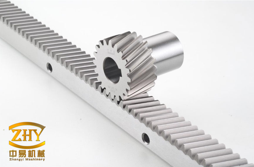
The torque of a rack and pinion gear actuator is often approximated as constant because the pitch radius of the pinion does not change during rotation. The basic torque equation is:
$$T_{RP}=\eta_{RP}\left(pA_p-F_s\right)r_p$$
Where \(p\) is the gauge air pressure, \(A_p\) is the effective piston area, \(F_s\) is the spring force if a spring is present, \(r_p\) is the pinion pitch radius, and \(\eta_{RP}\) is the efficiency of the rack and pinion gear. For a spur gear, the pitch radius can be related to the module and number of teeth:
$$r_p=\frac{mz}{2}$$
Where \(m\) is the module and \(z\) is the number of teeth on the pinion. This equation shows why the rack and pinion gear actuator is so predictable. If the piston force is constant and the pinion pitch radius is constant, the output torque is nearly constant throughout the stroke. That is a major advantage in some applications and a disadvantage in others.
Technical Comparison
I compare fork and rack and pinion gear actuators across several dimensions: torque profile, size, weight, air consumption, sealing, wear, maintenance, cost, and application fit. The following table summarizes the main differences I have observed.
| Feature | Fork Actuator | Rack and Pinion Gear Actuator |
|---|---|---|
| Motion conversion | Fork and pin or roller | Rack and pinion gear |
| Torque profile | Nonlinear, highest at ends | Nearly constant |
| Maximum torque at 0 and 90 degrees | Yes, by design | No, torque is roughly flat |
| Minimum torque at mid-stroke | Common | Not typical |
| Size for same torque | Often smaller and lighter | Often larger for high torque |
| Air consumption | Usually lower for equivalent torque | Usually higher for equivalent torque |
| Mechanical efficiency | Good, but linkage losses exist | High for a well-made rack and pinion gear |
| Maintenance | More components, more inspection points | Simple, fewer moving parts |
| Manufacturing maturity | Well established in high-torque service | Very mature and widely available |
| Typical application | High-torque ball and butterfly valves | Small and medium quarter-turn valves |
| Fail-safe spring return | Common and powerful | Common and compact |
| Manual override | Available, often heavy duty | Available, often simpler |
| Cost | Often higher at very high torque | Often lower at low and medium torque |
In my selection work, I do not treat the rack and pinion gear actuator as a lower-performance device. It is a high-performance device within its torque range. The rack and pinion gear design is compact, efficient, and easy to maintain. However, when the valve torque demand rises sharply at the ends of travel, the rack and pinion gear may need to be oversized to meet the end torque. That oversizing can increase weight, air consumption, and cost. A fork actuator can sometimes meet the same end torque with a smaller cylinder because its mechanical advantage is highest at the ends.
Torque Comparison in Detail
The torque comparison between fork and rack and pinion gear actuators is the heart of the selection decision. I often plot both curves against the valve torque curve. The valve torque curve for a ball valve or butterfly valve usually has high breakaway torque at the seat, lower running torque in the mid-stroke, and high seating torque at the end. A fork actuator naturally follows this pattern. A rack and pinion gear actuator provides a flat torque line, so it must be sized so that the flat line is above the highest point of the valve torque curve.
For a normalized comparison, I define the fork torque factor and the rack and pinion gear torque factor as follows:
$$f_F(\theta)=1-\left(1-\frac{T_{min}}{T_{max}}\right)\sin^2(2\theta)$$
$$f_{RP}(\theta)=1$$
If I assume a fork actuator with \(T_{max}=2000\) N·m and \(T_{min}=1000\) N·m, and a rack and pinion gear actuator with a constant torque of \(1500\) N·m, the comparison is clear.
| Shaft Angle | Fork Torque Factor | Fork Torque Example | Rack and Pinion Gear Torque Factor | Rack and Pinion Gear Torque Example |
|---|---|---|---|---|
| 0 degrees | 1.00 | 2000 N·m | 1.00 | 1500 N·m |
| 15 degrees | 0.93 | 1866 N·m | 1.00 | 1500 N·m |
| 30 degrees | 0.75 | 1500 N·m | 1.00 | 1500 N·m |
| 45 degrees | 0.50 | 1000 N·m | 1.00 | 1500 N·m |
| 60 degrees | 0.75 | 1500 N·m | 1.00 | 1500 N·m |
| 75 degrees | 0.93 | 1866 N·m | 1.00 | 1500 N·m |
| 90 degrees | 1.00 | 2000 N·m | 1.00 | 1500 N·m |
If the valve requires 1200 N·m at 0 degrees, 800 N·m at 45 degrees, and 1200 N·m at 90 degrees, both actuators can work. The rack and pinion gear actuator has excess torque in the middle, but that is acceptable. If the valve requires 1800 N·m at 0 and 90 degrees, the rack and pinion gear actuator with 1500 N·m cannot work, but the fork actuator can. This is why I always compare the full torque curve, not just a single rated torque value.
Spring Return and Fail-Safe Behavior
Single-acting actuators are often required for fail-safe operation. When air pressure is lost, the spring must move the valve to the safe position. The spring must overcome packing friction, bearing friction, fluid torque, and any unbalanced torque. For a single-acting rack and pinion gear actuator, the net torque is:
$$T_{net,RP}=\eta_{RP}\left(pA_p-F_s\right)r_p$$
For a single-acting fork actuator, the net torque is:
$$T_{net,F}=\eta_F\left(F_p-F_s\right)r_{eff}(\theta)$$
The spring force itself can be modeled as:
$$F_s(x)=F_0+kx$$
Where \(F_0\) is the initial spring preload and \(k\) is the spring rate. In a fork actuator, the effective radius changes with angle, so the spring torque also changes with angle. In a rack and pinion gear actuator, the spring torque is more nearly proportional to the spring force because the pinion pitch radius is constant. This makes the spring return behavior of the rack and pinion gear actuator easier to predict. However, the fork actuator can be designed with a spring that provides high torque at the seated position, which is often exactly what a fail-safe valve needs.
| Fail-Safe Consideration | Fork Actuator | Rack and Pinion Gear Actuator |
|---|---|---|
| Spring torque at seated position | Can be high due to geometry | Depends mainly on spring force and pinion radius |
| Spring torque at mid-stroke | May drop with effective radius | More uniform |
| Spring size for high torque | Often compact due to mechanical advantage | May require larger spring or cylinder |
| Prediction of return torque | Requires geometry data | Simpler with rack and pinion gear equations |
| Typical use | Emergency shutdown and high-torque fail-safe | General fail-safe and compact assemblies |
Air Consumption and Energy Use
Air consumption is often overlooked during actuator selection. I have seen projects where the actuator torque was correct, but the compressed air system could not support the required cycle time. The air consumption of a double-acting actuator for one full cycle can be approximated as:
$$V_{DA,cycle}=2\frac{\pi D^2}{4}S\frac{p_{abs}}{p_{atm}}$$
For a single-acting actuator, air is usually supplied to only one side, so the cycle consumption is approximately:
$$V_{SA,cycle}=\frac{\pi D^2}{4}S\frac{p_{abs}}{p_{atm}}$$
These are ideal values. Actual consumption depends on dead volume, seal leakage, tubing volume, valve manifold volume, and the action of the spring chamber. In general, the fork actuator can produce more torque for a given cylinder volume because of its mechanical advantage. The rack and pinion gear actuator may require a larger cylinder to achieve the same end torque, which increases air consumption. This is one reason I often select a fork actuator for high-torque, high-cycle applications.
| Parameter | Fork Actuator | Rack and Pinion Gear Actuator |
|---|---|---|
| Torque per unit cylinder volume | High at end positions | Moderate and uniform |
| Air consumption at equal end torque | Often lower | Often higher |
| Cycle time | Can be fast, but depends on porting | Usually fast and predictable |
| Compressor load | Lower if sized correctly | Higher if oversized for end torque |
| Energy cost | Can be lower over life | Can be higher over life |
Mechanical Efficiency and Wear
I pay close attention to efficiency and wear because they determine long-term reliability. A rack and pinion gear actuator has a direct gear engagement. When the rack and pinion gear are properly machined, aligned, and lubricated, the efficiency is high. The load is distributed across the gear teeth, and the pinion shaft is supported by bearings. However, side loading can occur if the rack is not balanced. A double-rack design reduces this side load and improves life.
A fork actuator has a more complex load path. The piston force is transferred through the fork, pin, roller, and disc. Each interface can wear. The pin and roller must be hardened and lubricated. The fork slots must be smooth and properly aligned. When the actuator is well made, the fork actuator can last millions of cycles. In my experience, the fork actuator is very robust in high-torque service, but it requires more attention to lubrication and inspection. The rack and pinion gear actuator is simpler to inspect and often easier to rebuild.
| Wear Factor | Fork Actuator | Rack and Pinion Gear Actuator |
|---|---|---|
| Main contact surfaces | Fork slot, pin, roller, disc | Rack teeth, pinion teeth, bearings |
| Side loading | Can be controlled by design | Reduced by dual rack or bearing support |
| Lubrication sensitivity | Moderate to high | Moderate |
| Backlash | Can increase with wear | Depends on gear quality |
| Field repair | More steps | Often simpler |
| Cycle life potential | Very high when properly maintained | Very high in clean service |
Selection Methodology
I follow a step-by-step method when I select between a fork actuator and a rack and pinion gear actuator. The method prevents me from choosing based on habit or catalog availability alone.
| Step | Action | Key Data |
|---|---|---|
| 1 | Define valve torque curve | Break, run, seat, unseat, packing, bearing, fluid torque |
| 2 | Apply safety factor | Service severity, temperature, wear, uncertainty |
| 3 | Compare actuator torque curves | Fork profile vs rack and pinion gear profile |
| 4 | Choose action type | Double-acting or spring-return single-acting |
| 5 | Check air supply | Pressure, flow, dew point, consumption |
| 6 | Check environment | Temperature, corrosion, dust, vibration, hazardous area |
| 7 | Select accessories | Positioner, solenoid, limit switch, filter regulator, manual override |
| 8 | Verify mounting interface | ISO 5211, stem dimensions, bracket, coupling |
| 9 | Evaluate life-cycle cost | Capital cost, air cost, maintenance cost, downtime cost |
| 10 | Confirm with vendor and test data | Certified torque curves, cycle test reports |
Step 1 is the most important. I request a valve torque curve from the valve manufacturer. If the curve is not available, I calculate it using the valve geometry, seat material, pressure drop, and fluid properties. The following equations are useful for estimating valve torque components.
$$T_{seat}=\mu_s F_{seat} r_s$$
$$T_{pack}=\mu_p F_{pack}\frac{d_s}{2}$$
$$T_{bearing}=\mu_b F_b r_b$$
$$T_{fluid}=C_d A\Delta P r_m$$
Where \(\mu_s\) is the seating friction coefficient, \(F_{seat}\) is the seating force, \(r_s\) is the seat radius, \(\mu_p\) is the packing friction coefficient, \(F_{pack}\) is the packing force, \(d_s\) is the stem diameter, \(\mu_b\) is the bearing friction coefficient, \(F_b\) is the bearing load, \(r_b\) is the bearing radius, \(C_d\) is a discharge coefficient, \(A\) is a reference area, \(\Delta P\) is the pressure drop, and \(r_m\) is a moment arm. These equations are approximate, but they help me identify the dominant torque terms. If the seating torque dominates, I may favor a fork actuator because it can be strong at the ends. If the running torque dominates and is fairly constant, I may favor a rack and pinion gear actuator.
Application Scenarios
I have selected both actuator types in many services. The following table shows how I usually map applications to actuator type. These are guidelines, not absolute rules. The torque curve always decides.
| Application | Preferred Actuator | Reason |
|---|---|---|
| High-pressure ball valve | Fork actuator | High breakaway and seating torque at ends |
| Large butterfly valve | Fork actuator | High torque at closed position and compact size |
| Small quarter-turn valve | Rack and pinion gear actuator | Compact, economical, and uniform torque |
| Fast on-off service | Rack and pinion gear actuator | Simple mechanics and fast response |
| Emergency shutdown | Fork actuator or rack and pinion gear actuator | Depends on required spring torque and valve torque profile |
| Modulating control | Rack and pinion gear actuator | Uniform torque and good positioner compatibility |
| High cycle life | Fork actuator or rack and pinion gear actuator | Both can be durable if properly sized and maintained |
| Offshore compact skid | Rack and pinion gear actuator | Small envelope and low weight |
| High torque, limited space | Fork actuator | High torque density at end positions |
Case Study: High-Torque Ball Valve
I once evaluated a large ball valve in a high-pressure gas line. The valve required 18,000 N·m to unseat, 9,000 N·m to run, and 17,000 N·m to seat. The available air pressure was 5 bar. A rack and pinion gear actuator with a constant torque of 20,000 N·m would have been very large and heavy. A fork actuator with a torque curve peaking at 22,000 N·m at the ends and dropping to 11,000 N·m at mid-stroke was much more compact. The valve torque curve matched the fork curve, so the fork actuator was the better choice. The rack and pinion gear actuator would have worked, but it would have required a larger cylinder, higher air consumption, and a heavier mounting bracket.
Case Study: Small Butterfly Valve
In another project, I selected an actuator for a 6-inch butterfly valve in a water line. The valve required 350 N·m at breakaway, 220 N·m running, and 330 N·m seating. The air pressure was 6 bar. A rack and pinion gear actuator with a constant torque of 450 N·m was compact, inexpensive, and easy to mount. A fork actuator would also have worked, but it would have been larger than necessary for the available space. The rack and pinion gear actuator provided enough torque margin, and its flat torque curve was more than adequate for the relatively low valve torque variation. This is a typical example where the rack and pinion gear is the practical choice.
Common Selection Errors
I have seen several recurring errors in actuator selection. I list them here because avoiding them is often more valuable than memorizing catalog numbers.
| Error | Consequence | Correction |
|---|---|---|
| Sizing only by cylinder bore | Insufficient torque at the ends | Compare full torque curves, not just bore size |
| Ignoring valve torque profile | Stall, leakage, or seat damage | Obtain or calculate break, run, and seat torque |
| Using too low a safety factor | Failure as packing wears or temperature changes | Apply appropriate \(S_f\) for the service |
| Ignoring air consumption | Slow stroke or pressure drop | Calculate cycle consumption and check compressor capacity |
| Forgetting spring return torque | Valve does not fail safe | Verify spring torque at every angle |
| Wrong mounting interface | Misalignment, stem damage, leakage | Check ISO 5211 and stem dimensions |
| Ignoring backlash | Poor modulation and positioner hunting | Specify acceptable backlash for the rack and pinion gear |
| Ignoring manual override | Long downtime during air failure | Select manual override type and access |
| Ignoring corrosion | Seized actuator or external damage | Specify coating, material, and IP rating |
| Choosing on capital cost alone | High air and maintenance cost | Evaluate life-cycle cost |
Torque Margin and Safety Factor
I use a torque margin table to document my selection. The table below shows a typical approach. The exact values depend on the process and the criticality of the valve.
| Service Condition | Minimum Safety Factor \(S_f\) | Recommended Margin |
|---|---|---|
| Clean fluid, moderate temperature, low cycle | 1.25 | 25% |
| General process service | 1.30 | 30% |
| High temperature or high cycle | 1.40 | 40% |
| Slurry, abrasive, or scaling service | 1.50 | 50% |
| Emergency shutdown or critical isolation | 1.50 to 2.00 | 50% to 100% |
The safety factor should be applied to the required valve torque, not to the actuator rated torque. I also check the actuator torque at the actual available air pressure. Catalog torque is often based on a nominal pressure such as 5.5 bar or 6 bar. If the plant air pressure is 4 bar, the available torque is lower. The relationship is approximately linear with pressure for a double-acting actuator:
$$T_{available}=T_{rated}\frac{p_{available}}{p_{rated}}$$
For a spring-return actuator, the relationship is more complex because the spring force opposes the air force. The net torque is:
$$T_{net}=T_{air}-T_{spring}$$
I always verify that \(T_{net}\) is positive and sufficient at every angle, especially near the fail-safe position.
Rack and Pinion Gear Backlash and Modulation
When I apply a rack and pinion gear actuator in modulating service, I pay attention to backlash. Backlash is the lost motion between the rack and pinion gear teeth. A small amount of backlash is normal and necessary for lubrication and thermal expansion. Excessive backlash can cause the positioner to hunt, reduce control accuracy, and increase wear. For high-resolution control, I specify a rack and pinion gear actuator with tight manufacturing tolerances, proper bearing support, and a positioner that can compensate for minor dead band. I also consider the valve characteristics. A butterfly valve with a positioner may be more sensitive to backlash than a ball valve used for on-off service.
The rack and pinion gear actuator is often preferred for modulating service because its torque is uniform and its response is predictable. The fork actuator can also be used for modulating service, but the nonlinear torque curve must be considered. The positioner must be tuned for the changing mechanical advantage. In some cases, the nonlinear curve is beneficial because it provides higher torque at the ends where the valve needs it. In other cases, it complicates tuning. I decide based on the valve torque curve and the required control accuracy.
Materials, Seals, and Environment
The environment affects both the fork actuator and the rack and pinion gear actuator. I consider temperature, humidity, corrosive atmosphere, dust, salt spray, radiation, and vibration. Seals are often the first components to fail. Nitrile rubber is common for moderate temperatures. Viton or fluorocarbon is used for higher temperatures and chemical resistance. Silicone, EPDM, and PTFE-based seals are used in special services. The cylinder bore and piston surface must be protected from corrosion. Hard anodized aluminum, stainless steel, or coated carbon steel may be required. The rack and pinion gear teeth need proper lubrication and protection from contaminants. The fork actuator pins and rollers need wear-resistant surfaces and good lubrication.
| Environment | Fork Actuator Consideration | Rack and Pinion Gear Consideration |
|---|---|---|
| High temperature | Spring relaxation, seal degradation, lubrication loss | Gear lubrication, seal degradation, thermal expansion |
| Low temperature | Seal stiffening, brittle spring, ice formation | Seal stiffening, gear lubrication viscosity |
| Corrosive atmosphere | Pin and fork corrosion | Rack and pinion gear corrosion, bearing corrosion |
| Dusty environment | Fork slot contamination | Rack and pinion gear contamination |
| Offshore salt spray | Coating and stainless hardware | Coating and sealed bearings |
| Vibration | Fastener loosening, pin wear | Bearing wear, backlash increase |
Accessories and Control Integration
An actuator is rarely installed alone. I integrate it with a positioner, solenoid valve, limit switch box, air filter regulator, pressure gauge, quick exhaust valve, and manual override. The accessory package affects performance and cost. A rack and pinion gear actuator often has a standard accessory mounting pad, which simplifies integration. A fork actuator may have a larger body and different mounting dimensions, so the accessory package must be planned carefully. For emergency shutdown, I often specify a solenoid valve with a quick exhaust and a spring-return actuator. For modulating control, I specify an electro-pneumatic positioner with the correct cam profile for the actuator and valve.
| Accessory | Purpose | Fork Actuator Note | Rack and Pinion Gear Note |
|---|---|---|---|
| Positioner | Modulating control | Cam must match nonlinear torque | Standard linear cam often works |
| Solenoid valve | On-off and emergency action | Check flow capacity for large cylinder | Compact manifold often available |
| Limit switch box | Position feedback | Mounting bracket may be larger | Standard mounting pad |
| Filter regulator | Clean and stable air supply | Size for cylinder volume | Size for cylinder volume |
| Quick exhaust | Fast stroke | Useful for large volume | Useful for fast on-off |
| Manual override | Emergency operation | Heavy-duty handwheel available | Declutchable or handwheel available |
Cost and Life-Cycle Analysis
I never select an actuator on purchase price alone. The life-cycle cost includes capital cost, installation cost, air consumption, maintenance, spare parts, downtime, and energy. A rack and pinion gear actuator may have a lower initial cost for low-torque applications. A fork actuator may have a higher initial cost but lower air consumption and a smaller mounting structure. The following equation is a simple life-cycle cost model:
$$LCC=C_{capital}+C_{install}+C_{air}+C_{maintenance}+C_{downtime}$$
I estimate air cost using the compressor power and the cycle volume:
$$C_{air}=N_{cycles}\frac{V_{cycle}p_{abs}}{p_{atm}}C_{unit}$$
Where \(N_{cycles}\) is the number of cycles per year and \(C_{unit}\) is the cost per unit volume of compressed air. For high-cycle applications, the air cost can exceed the capital cost difference between a fork actuator and a rack and pinion gear actuator. This is a strong argument for the fork actuator when it can deliver the required torque with a smaller cylinder.
| Cost Factor | Fork Actuator | Rack and Pinion Gear Actuator |
|---|---|---|
| Initial purchase | Often higher at very high torque | Often lower at low and medium torque |
| Mounting structure | Can be lighter | Can be heavier if oversized |
| Air consumption | Often lower | Often higher |
| Maintenance | More inspection points | Fewer moving parts |
| Spare parts | More variety | Standardized |
| Downtime risk | Depends on maintenance quality | Depends on gear and bearing quality |
Practical Selection Rules
I use the following practical rules when I compare a fork actuator and a rack and pinion gear actuator. These rules are based on torque curve matching, available space, air supply, and maintenance philosophy.
| Condition | Preferred Choice | Reason |
|---|---|---|
| Valve torque peaks at 0 and 90 degrees | Fork actuator | Fork torque peaks at the ends |
| Valve torque is nearly constant | Rack and pinion gear actuator | Rack and pinion gear torque is nearly constant |
| High torque in a small envelope | Fork actuator | High torque density at end positions |
| Low torque and low cost | Rack and pinion gear actuator | Mature, compact, and economical |
| Very high cycle rate | Either, with proper sizing | Compare air consumption and wear life |
| Modulating control with uniform torque | Rack and pinion gear actuator | Predictable torque and good positioner compatibility |
| Fail-safe with high end torque | Fork actuator | Spring torque can be higher at seated position |
| Simple maintenance and standard parts | Rack and pinion gear actuator | Fewer components and wide availability |
| High torque and limited air supply | Fork actuator | Lower air consumption for equivalent end torque |
Verification and Documentation
Before I release an actuator selection, I document the torque curve comparison. I include the valve torque curve, the actuator torque curve, the safety factor, the air pressure basis, the spring return curve, and the accessory list. I also verify the mounting interface and the stroke stops. The travel stops must allow precise adjustment of the open and closed positions. The actuator must not rely on the valve seat to stop the stroke. The stops should be accessible and lockable. For a rack and pinion gear actuator, the travel stops are often external screws. For a fork actuator, the travel stops may be located on the housing or cylinder. I check that the stop adjustment range covers the required valve rotation.
I also verify the following:
| Verification Item | Acceptance Criterion |
|---|---|
| Actuator torque at minimum air pressure | Greater than required torque times safety factor |
| Spring return torque | Greater than required fail-safe torque at every angle |
| Stroke time | Within process and safety requirements |
| Air consumption | Within compressor and tubing capacity |
| Mounting interface | Matches ISO 5211 and stem dimensions |
| Travel stops | Adjustable and lockable |
| Accessories | Compatible with actuator and control system |
| Environment | Materials and seals suitable for service |
| Manual override | Accessible and operable under load |
| Documentation | Torque curves, certificates, and manuals available |
Final Recommendations
In my work, I treat the fork actuator and the rack and pinion gear actuator as complementary technologies. The rack and pinion gear actuator is a strong choice for low and medium torque, compact assemblies, fast on-off service, and applications where a uniform torque curve is acceptable. It is simple, mature, and easy to integrate. The fork actuator is a strong choice for high torque, high pressure drop, large ball and butterfly valves, and fail-safe applications where the valve torque peaks at the ends. It can provide high torque density, lower air consumption, and a torque curve that naturally matches many quarter-turn valves.
The selection decision should always be based on the valve torque curve, the available air pressure, the required safety factor, the fail-safe requirement, the environment, the cycle rate, and the life-cycle cost. I never assume that one actuator type is always better. I compare the curves, check the margins, verify the spring, and document the result. When I follow this method, the rack and pinion gear actuator and the fork actuator each find their proper place in the control valve assembly.
For any critical valve, I recommend a detailed torque study before purchase. The study should include breakaway, running, and seating torque; packing and bearing friction; fluid dynamic torque; thermal effects; and the actuator torque at the minimum available air pressure. The study should also include the spring return curve for single-acting actuators. With this information, the choice between a fork actuator and a rack and pinion gear actuator becomes a technical decision rather than a guess. The result is a control valve that opens, closes, modulates, and fails safely as intended throughout its service life.