
In my daily work as an instrumentation and control system designer, I am frequently required to select the most suitable pneumatic actuator for a control valve, an on-off valve, or an emergency shutdown valve. I have learned that actuator selection is not a simple catalogue exercise. It is a technical decision that combines torque demand, stroke, spring behavior, air supply quality, valve type, process dynamics, maintenance philosophy, and life-cycle cost. Among the many actuator families I evaluate, two are especially common for quarter-turn valves: the fork-style pneumatic piston actuator and the rack and pinion actuator. Both convert linear piston motion into rotary shaft motion, but they do so with different geometry, different torque profiles, and different practical strengths. In this article I explain how I compare them, what formulas I use, and why I often reach different conclusions for different services.
My starting point is always the valve torque requirement. A valve does not require a single torque value at every position. The torque needed to unseat a butterfly valve, to rotate a ball valve, or to overcome packing friction can vary significantly with angle. If I ignore that variation and simply choose an actuator with a rated torque above the valve’s maximum torque, I may either over-size the actuator or under-size it at the critical seating and unseating positions. Therefore, I begin with a torque audit.
$$T_{required}(\theta) = T_{valve}(\theta) + T_{packing}(\theta) + T_{bearing}(\theta) + T_{seat}(\theta) + T_{dynamic}(\theta)$$
In this equation, \(T_{required}(\theta)\) is the total torque required from the actuator at shaft angle \(\theta\). \(T_{valve}(\theta)\) is the inherent valve torque, \(T_{packing}(\theta)\) is packing friction, \(T_{bearing}(\theta)\) is bearing friction, \(T_{seat}(\theta)\) is seating or unseating torque, and \(T_{dynamic}(\theta)\) represents dynamic flow forces. I use this expression as a mental model even when the valve manufacturer supplies a simpler torque table. The key point is that the actuator must satisfy the entire torque curve, not just one number.
My View of Pneumatic Piston Actuator Families
Pneumatic actuators can be divided broadly into diaphragm actuators and piston actuators. Diaphragm actuators are simple, reliable, and well suited to many linear control valve applications. Piston actuators, however, are my usual choice when I need high output force, long stroke, high pressure differential, high static pressure, or a compact quarter-turn package. Piston actuators can be linear or rotary. In rotary service, the two dominant mechanical conversions are the fork mechanism and the rack and pinion mechanism. I think of the fork style as a torque-shaping mechanism and the rack and pinion style as a torque-transfer mechanism.
Piston actuators can also be classified by action and spring arrangement. A double-acting actuator uses air pressure to move the piston in both directions. A single-acting actuator uses air pressure in one direction and a spring for the return stroke. A spring-return actuator is often required for fail-safe operation. I must decide whether the valve should fail closed, fail open, or fail last. That decision affects spring size, air pressure, and actuator volume. It also affects the comparison between fork-style actuators and rack and pinion actuators because the spring return path is different in each design.
| Classification Basis | Type | My Typical Use |
|---|---|---|
| Motion output | Linear piston actuator | High-thrust globe valve, gate valve, damper |
| Motion output | Rotary piston actuator | Ball valve, butterfly valve, plug valve, damper |
| Action | Double acting | Normal on-off service with reliable air supply |
| Action | Single acting spring return | Fail-safe shutdown or fail-safe open service |
| Mechanical conversion | Fork style | High torque, large valve, compact envelope |
| Mechanical conversion | Rack and pinion | Moderate torque, compact package, simple maintenance |
I have found that the classification table above is useful during early project discussions because it forces the team to agree on the service requirement before comparing hardware. A double-acting rack and pinion actuator and a single-acting fork actuator may have similar physical dimensions, but their failure modes and torque availability are completely different. I never allow a selection to proceed until the action, spring mode, and valve torque curve are all confirmed.
Fork-Style Actuator Architecture and Working Principle
A fork-style pneumatic piston actuator uses a piston that moves linearly inside a cylinder. The piston is connected to a fork, and the fork engages a roller or pin on a rotary disc. As the piston strokes, the fork pushes or pulls the pin, causing the disc and output shaft to rotate. The result is a quarter-turn output, usually limited to 90 degrees. I often describe the fork mechanism as a geometrical torque multiplier because the effective lever arm changes with angle.
The main components I look for in a fork-style actuator include the cylinder body, end caps, piston, piston rod, fork, guide block, rotary disc, output shaft, bearings, seals, spring pack, travel stops, and accessory mounting interfaces. In a single-acting version, the spring pack is usually arranged concentrically or alongside the piston. In a double-acting version, air ports on both sides of the piston provide bidirectional motion. The fork and roller interface is the heart of the design. If that interface is poorly guided, the actuator can suffer side loading, seal wear, and premature failure.
The torque curve of a fork-style actuator is not flat. It is typically highest near the fully open and fully closed positions and lowest near the mid-stroke. This behavior is advantageous for many quarter-turn valves because ball valves and butterfly valves often require the highest torque at the seat and the lowest torque in the middle of travel. The fork geometry can be designed so that the maximum actuator torque occurs exactly where the valve needs it most.
$$T_{fork}(\theta) = F_{piston} \cdot L_{effective}(\theta)$$
In this expression, \(T_{fork}(\theta)\) is the output torque at angle \(\theta\), \(F_{piston}\) is the force produced by the piston, and \(L_{effective}(\theta)\) is the effective lever arm of the fork mechanism. Because \(L_{effective}(\theta)\) changes with angle, the torque curve can be shaped. A well-designed fork actuator may produce a torque curve that matches the valve torque curve closely, which reduces unnecessary over-sizing.
I also examine the spring behavior of fork-style actuators carefully. In a single-acting fork actuator, the spring must overcome the valve torque during the return stroke. The spring force is not constant; it depends on compression. Therefore, the available return torque is highest when the spring is most compressed and lowest when the spring is least compressed. I must compare the spring return torque curve with the valve torque curve at every angle. If the spring is marginal at the seating position, the valve may fail to close fully on loss of air.
$$T_{spring}(\theta) = F_{spring}(x(\theta)) \cdot L_{effective}(\theta)$$
Here, \(F_{spring}(x(\theta))\) is the spring force at the compressed length corresponding to angle \(\theta\). This formula reminds me that spring return torque is not a single value. It is a curve. I always request the spring return torque curve from the actuator vendor, not just the end-of-stroke spring torque.
Rack and Pinion Actuator Architecture and Working Principle
A rack and pinion actuator uses a piston with a rack tooth profile that meshes with a pinion gear on the output shaft. When air pressure pushes the piston, the rack moves linearly, and the rack and pinion gears convert that linear motion into rotation. The pinion gear is mounted on the output shaft, so the shaft rotates through the required quarter-turn angle. I often choose this design when I need a compact, simple, and cost-effective actuator for moderate torque requirements.
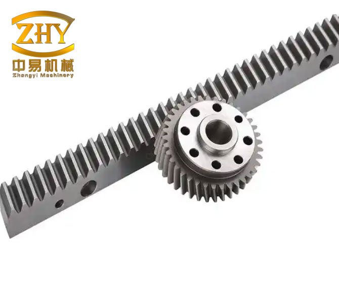
When I inspect a rack and pinion actuator, I pay close attention to the rack and pinion gears because they determine the mechanical efficiency, backlash, and torque transmission. The rack and pinion gears are usually manufactured with a specific pressure angle and tooth profile. The quality of the rack and pinion gears affects noise, wear, and positional repeatability. In high-cycle applications, I prefer hardened rack and pinion gears with precise tooth grinding. The rack and pinion gears must also be properly lubricated because the sliding contact at the tooth flanks can generate friction and heat.
The basic torque relationship for a rack and pinion actuator is simpler than that of a fork actuator. The effective lever arm is approximately the pitch radius of the pinion gear, so the torque is relatively constant throughout the stroke. This is a major advantage when the valve torque demand is also relatively constant. However, if the valve requires a high unseating torque and a low running torque, a rack and pinion actuator may need to be oversized to meet the peak torque. That oversizing can increase air consumption, weight, and cost.
$$T_{rack\ and\ pinion}(\theta) \approx F_{piston} \cdot r_{pinion}$$
In this equation, \(r_{pinion}\) is the pitch radius of the pinion gear. Since \(r_{pinion}\) is essentially constant, the output torque is nearly constant with angle. I use this approximation for initial sizing and then verify it with vendor data. The actual torque may vary slightly due to friction, seal drag, and tooth contact effects, but the fundamental behavior is close to constant.
I also consider the number of teeth on the rack and pinion gears. A larger pinion pitch radius produces more torque for the same piston force, but it also requires a longer piston stroke for a 90-degree rotation. A smaller pinion pitch radius reduces the required stroke but reduces torque. This trade-off is central to rack and pinion actuator design. When I compare two rack and pinion actuators of similar envelope size, I look at the rack and pinion gears to understand the torque-stroke compromise.
The rack and pinion gears in a double-acting actuator are usually arranged symmetrically. One piston moves in one direction while the other moves in the opposite direction, or a single piston with two racks drives a single pinion. In a single-acting version, the spring returns the piston and the rack and pinion gears transmit the spring force to the shaft. I always verify that the rack and pinion gears are rated for the spring return torque, not only the air stroke torque. A common mistake is to size the actuator for the air stroke and forget that the spring return path passes through the same rack and pinion gears.
Direct Technical Comparison
When I compare fork-style and rack and pinion actuators, I do not rely on general statements such as “fork is stronger” or “rack and pinion is cheaper.” I use a structured comparison. The table below summarizes the attributes I evaluate. I have used this table in many projects, and it helps me explain the selection to process engineers, mechanical engineers, and maintenance teams.
| Attribute | Fork-Style Actuator | Rack and Pinion Actuator |
|---|---|---|
| Motion conversion | Fork and roller or pin driving a rotary disc | Rack and pinion gears driving the output shaft |
| Torque curve | Varies with angle; often highest at ends | Nearly constant with angle |
| Typical torque range | High to very high | Low to moderate; high with larger sizes |
| Envelope size | Compact for high torque | Compact for moderate torque |
| Weight | Often lighter for same high torque | Often heavier when oversized for peak torque |
| Mechanical efficiency | Good, but depends on fork geometry and guides | High, especially with precision rack and pinion gears |
| Maintenance | More components; guide and roller wear must be checked | Simple; rack and pinion gears and seals are main wear points |
| Air consumption | Can be lower for same torque because of torque shaping | Can be higher if oversized for peak torque |
| Best fit | Large ball valves, butterfly valves, high torque shutdown valves | Small to medium ball valves, butterfly valves, dampers, general on-off service |
I want to emphasize that the “best fit” column is not absolute. I have used rack and pinion actuators on large valves when the torque curve was flat and the required torque was moderate. I have also used fork actuators on smaller valves when the available air pressure was low and the torque demand was peaky. The decision depends on the actual torque curve, the available air supply, the required failure mode, and the physical space available for installation.
Torque Behavior and Mathematical Comparison
The torque behavior of an actuator is the most important technical difference between the two designs. A rack and pinion actuator with constant pinion pitch radius produces a nearly flat torque curve. A fork actuator produces a shaped torque curve. I often plot both curves against the valve torque curve. If the valve torque curve is flat, the rack and pinion actuator may be a perfect match. If the valve torque curve has high peaks at the ends, the fork actuator may be a better match.
$$T_{rack\ and\ pinion}(\theta) = T_{constant}$$
$$T_{fork}(\theta) = T_{min} + (T_{max} – T_{min}) \left( \frac{\theta – \pi/4}{\pi/4} \right)^2$$
In the fork torque equation, \(\theta\) is measured in radians from the closed position, and the stroke is assumed to be 90 degrees or \(\pi/2\) radians. The minimum torque occurs near the middle of the stroke, and the maximum torque occurs at the ends. This parabolic approximation is useful for conceptual comparison. Real fork actuators may have a more complex curve, but the general shape is similar. I use this equation to explain why a fork actuator can be smaller than a rack and pinion actuator for the same peak torque requirement.
Let me consider a numerical example. Suppose a valve requires a peak torque of 2000 N·m at the closed position, a running torque of 800 N·m at mid-stroke, and a peak torque of 1800 N·m at the open position. A rack and pinion actuator with a constant torque of 2000 N·m would meet the requirement, but it would deliver 2000 N·m at mid-stroke even though only 800 N·m is needed. That excess torque may require a larger actuator, higher air consumption, and a stronger valve stem. A fork actuator could be designed to deliver 2000 N·m at the ends and 900 N·m at mid-stroke. The fork actuator would then be smaller and more efficient for this service.
| Valve Angle | Valve Torque Demand (N·m) | Rack and Pinion Torque (N·m) | Fork Torque (N·m) |
|---|---|---|---|
| 0° closed | 2000 | 2000 | 2000 |
| 15° | 1500 | 2000 | 1750 |
| 30° | 1100 | 2000 | 1250 |
| 45° mid | 800 | 2000 | 900 |
| 60° | 1100 | 2000 | 1250 |
| 75° | 1500 | 2000 | 1750 |
| 90° open | 1800 | 2000 | 1800 |
In the table above, the rack and pinion actuator has enough torque at every angle, but it has excess torque in the middle of the stroke. The fork actuator matches the valve demand more closely. I use this type of table when I need to justify the selection to a project team. The numbers make the argument clearer than a qualitative statement.
However, I also recognize the limitations of the fork actuator. The fork mechanism has more sliding contact and more guide surfaces than a simple rack and pinion pair. If the fork is not properly guided, the side load on the piston and seals can increase. The rack and pinion actuator, with its direct rack and pinion gears, can be more efficient in a clean, well-lubricated environment. I therefore consider both the torque curve and the mechanical complexity.
Selection Criteria I Use
When I select an actuator, I follow a systematic process. I do not begin with a preferred technology. I begin with the valve and the process. The following list is the sequence I use. I have refined it over many projects, and it helps me avoid common errors.
- Determine the valve type and required quarter-turn angle.
- Obtain the valve torque curve from the valve manufacturer.
- Identify the failure mode: fail closed, fail open, or fail last.
- Determine the available air supply pressure and quality.
- Calculate the required actuator torque with a safety factor.
- Compare fork-style and rack and pinion candidates using torque curves.
- Check the spring return torque curve for single-acting service.
- Check air consumption and required compressor capacity.
- Check envelope, weight, and mounting interface.
- Check maintenance access and spare parts availability.
- Review life-cycle cost and project schedule.
- Confirm the selection with the valve and actuator vendors.
The safety factor is a critical part of this process. I never size an actuator at exactly the valve torque. I use a factor that depends on the service. For clean, well-lubricated, low-cycle service, I may use a factor of 1.25 to 1.5. For dirty, high-cycle, or high-temperature service, I may use 1.5 to 2.0 or higher. The safety factor accounts for friction changes, packing wear, process fouling, and air pressure variations.
$$T_{actuator,rated} \ge SF \cdot T_{valve,max}$$
In this inequality, \(T_{actuator,rated}\) is the rated actuator torque, \(SF\) is the safety factor, and \(T_{valve,max}\) is the maximum valve torque. I also check the actuator torque at the actual air pressure, not just the nominal rated pressure. If the plant air supply is 5 bar but the actuator is rated at 7 bar, the available torque may be significantly lower.
| Service Condition | Recommended Safety Factor | My Reason |
|---|---|---|
| Clean fluid, moderate temperature, low cycle | 1.25–1.5 | Low friction variation and slow wear |
| General process service, moderate cycle | 1.5–1.75 | Normal packing and seat wear |
| Dirty, abrasive, or polymerizing fluid | 1.75–2.0 | Fouling increases friction and seating torque |
| High temperature or high cycle | 1.75–2.25 | Thermal expansion and wear affect torque |
| Emergency shutdown, fail-safe | 2.0–2.5 | Spring return must overcome worst-case friction |
I also evaluate the air pressure available at the actuator. The force produced by a piston is proportional to the pressure difference across the piston. If the pressure is lower than expected, the torque will be lower. I use the following relationship for a double-acting cylinder.
$$F = P \cdot A – F_{friction} – F_{spring}$$
Here, \(F\) is the net piston force, \(P\) is the gauge pressure, \(A\) is the effective piston area, \(F_{friction}\) is seal and guide friction, and \(F_{spring}\) is the spring force if a spring is present. For a single-acting actuator, the spring force opposes the air stroke and assists the return stroke. I must calculate both directions separately.
Spring Return and Fail-Safe Behavior
Fail-safe behavior is one of the most important reasons I choose between fork-style and rack and pinion actuators. In a single-acting actuator, the spring must return the valve to its safe position when air pressure is lost. The spring return torque must be greater than the valve torque at every angle during the return stroke. This is a much stricter requirement than simply having enough air torque.
$$T_{spring,return}(\theta) \ge SF_{return} \cdot T_{valve,return}(\theta)$$
In this inequality, \(T_{spring,return}(\theta)\) is the spring return torque at angle \(\theta\), \(SF_{return}\) is the return safety factor, and \(T_{valve,return}(\theta)\) is the valve torque during the return stroke. The return safety factor is often higher than the air stroke safety factor because the spring force may degrade over time and because the return stroke may encounter additional friction after a period of inactivity.
For a fork-style actuator, the spring return torque is shaped by the fork geometry. This can be an advantage because the spring torque can be made high at the seating position. For a rack and pinion actuator, the spring return torque is transmitted through the rack and pinion gears and is relatively constant with angle. If the valve requires a high seating torque, the rack and pinion spring may need to be larger. I always compare the spring return torque curve with the valve return torque curve. I never accept a single “spring torque” number.
| Fail-Safe Requirement | Fork-Style Consideration | Rack and Pinion Consideration |
|---|---|---|
| High seating torque | Fork geometry can amplify torque at end positions | May require larger spring or larger pinion pitch radius |
| Mid-stroke friction | Torque may drop at mid-stroke; verify minimum | Torque is nearly constant; easier to predict |
| Spring size | Can be compact if torque shaping is favorable | Can be bulky if peak torque is high |
| Return speed control | Need to check spring force and exhaust capacity | Need to check rack and pinion gear lubrication and seal drag |
I also consider the effect of spring return on air consumption. In a single-acting actuator, the air stroke must compress the spring and also produce the required valve torque. Therefore, the air pressure must be high enough to overcome both. If the spring is too strong, the actuator may require higher air pressure, which increases energy consumption. If the spring is too weak, the valve may not fail safe. The design is a balance.
Air Consumption and Energy Efficiency
Air consumption is an important part of my actuator selection because it affects compressor size, operating cost, and overall plant energy efficiency. A double-acting actuator consumes air on both strokes. A single-acting actuator consumes air on one stroke and exhausts on the return stroke. The volume of air consumed depends on the piston area, stroke length, and number of strokes.
$$V_{DA} = (A_{open} + A_{close}) \cdot L \cdot \frac{P_{absolute}}{P_{atmospheric}}$$
In this equation, \(V_{DA}\) is the free air consumption for a double-acting actuator, \(A_{open}\) and \(A_{close}\) are the effective piston areas on the open and close sides, \(L\) is the stroke length, and the pressure ratio converts the compressed volume to free air. For a single-acting actuator, the return stroke does not consume air from the supply, but the spring must be compressed during the air stroke.
$$V_{SA} = A_{air} \cdot L \cdot \frac{P_{absolute}}{P_{atmospheric}}$$
I often compare the air consumption of a fork-style actuator and a rack and pinion actuator at the same output torque. Because the fork actuator can shape its torque curve, it may use a smaller piston and less air for a given peak torque. The rack and pinion actuator may need a larger piston to meet the peak torque, which increases air consumption. However, the rack and pinion actuator may have lower internal friction in some designs, which can partly offset the larger size. I use vendor air consumption tables and my own calculations to make the comparison.
| Actuator Type | Relative Air Consumption at Equal Peak Torque | My Observation |
|---|---|---|
| Fork style, double acting | Lower in many high-torque cases | Torque shaping reduces wasted mid-stroke torque |
| Rack and pinion, double acting | Moderate to higher when oversized for peak torque | Constant torque curve can waste air at mid-stroke |
| Fork style, single acting | Moderate | Spring design and fork geometry affect air demand |
| Rack and pinion, single acting | Moderate to higher | Spring and rack and pinion gears must be sized together |
I also consider the air supply quality. Rack and pinion gears and fork mechanisms both require clean, dry, lubricated air if the manufacturer specifies lubrication. Moisture can cause corrosion, and particulate can cause seal wear. In my experience, a rack and pinion actuator with precision rack and pinion gears is sensitive to contamination because the tooth contact can be damaged by hard particles. A fork actuator with a roller or pin interface may tolerate slightly more contamination, but it also has guide surfaces that can wear. I always recommend proper filtration and drying regardless of the technology.
Mechanical Efficiency and Losses
The mechanical efficiency of an actuator is the ratio of output torque to the torque equivalent of the input piston force. Losses come from seal friction, guide friction, bearing friction, and the mechanical conversion itself. The rack and pinion conversion can be very efficient because the tooth contact is rolling and sliding in a controlled manner. The fork conversion can also be efficient, but it depends on the guide design and the contact between the fork and roller.
$$\eta = \frac{T_{output} \cdot \theta}{F_{piston} \cdot x}$$
In this formula, \(\eta\) is the mechanical efficiency, \(T_{output}\) is the output torque, \(\theta\) is the output angle in radians, \(F_{piston}\) is the piston force, and \(x\) is the piston displacement. I use this formula when I compare vendor efficiency claims. A high efficiency means that less air pressure is needed to produce a given torque. However, efficiency is not the only factor. Reliability, maintenance, and torque curve matching are also important.
I have found that rack and pinion actuators with high-quality rack and pinion gears can achieve very good efficiency in clean service. Fork actuators can achieve comparable efficiency when the fork and roller are well guided and lubricated. In dirty service, the fork actuator may lose efficiency more quickly if the guide surfaces become contaminated. The rack and pinion actuator may lose efficiency if the rack and pinion gears become dry or contaminated. Both designs require maintenance.
Envelope, Weight, and Installation
Physical envelope is often a limiting factor in revamp projects. I have worked on installations where the available space around the valve was extremely tight. In those cases, the actuator with the smallest envelope for the required torque wins. Fork-style actuators are often more compact for high torque because the fork mechanism can produce a large torque with a relatively short piston stroke. Rack and pinion actuators are compact for moderate torque but can become large when they must meet a high peak torque.
Weight is also important. A heavy actuator can require additional pipe support, especially on small valves. It can also make manual operation more difficult. I prefer a lighter actuator when the valve is installed on a flexible piping system. The fork-style actuator often has a weight advantage in high-torque applications. The rack and pinion actuator often has a weight advantage in small and medium sizes because its construction is simple and compact.
| Installation Factor | Fork-Style Actuator | Rack and Pinion Actuator |
|---|---|---|
| Envelope at high torque | Compact | Can be large |
| Envelope at low torque | Can be larger than necessary | Very compact |
| Weight at high torque | Often lighter | Often heavier |
| Mounting interface | Standard quarter-turn flange | Standard quarter-turn flange |
| Accessory mounting | Often modular | Often modular |
| Manual override | Available; may require gearbox | Available; may require gearbox |
I always check the mounting interface. Both actuator types are available with standard ISO 5211 mounting patterns, but the actual dimensions can vary. I also check the stem connection, the keyway, and the bracket. A mismatch can cause backlash, misalignment, and premature stem wear. I prefer to select the actuator and valve from a single vendor or from vendors that have a proven interface history.
Maintenance, Reliability, and Life Cycle
Maintenance is a major factor in my selection. A rack and pinion actuator is generally simpler to maintain because it has fewer moving parts. The main wear items are the seals, bearings, and rack and pinion gears. The fork actuator has more moving parts, including the fork, roller, guide block, and rotary disc. However, the fork actuator may be more tolerant of certain types of contamination because the contact stresses are distributed differently. I consider the maintenance capabilities of the plant. If the plant has limited maintenance resources, I may prefer the simpler rack and pinion design unless the torque requirement demands a fork actuator.
Reliability is not just about the number of parts. It is also about the robustness of the design. A well-made fork actuator with proper guides and hardened contact surfaces can be extremely reliable. A poorly made rack and pinion actuator with soft rack and pinion gears can fail quickly. I always review the materials, heat treatment, and surface finishes. I also review the test data. A vendor that can provide cycle test results for the rack and pinion gears or the fork mechanism gives me more confidence.
| Maintenance Item | Fork-Style Actuator | Rack and Pinion Actuator |
|---|---|---|
| Seal replacement | Periodic | Periodic |
| Guide and roller inspection | Important | Not applicable |
| Rack and pinion gear inspection | Not applicable | Important |
| Lubrication | Per manufacturer | Per manufacturer |
| Travel stop adjustment | Periodic | Periodic |
| Spring inspection | For single acting | For single acting |
Life-cycle cost is the sum of initial cost, installation cost, maintenance cost, downtime cost, and energy cost. I have seen projects where the initial cost of a fork actuator was higher, but the life-cycle cost was lower because it consumed less air and required less maintenance. I have also seen projects where the rack and pinion actuator was the better choice because the initial cost was lower and the service was light. I never make a selection based only on purchase price.
| Life-Cycle Cost Factor | Fork-Style Actuator | Rack and Pinion Actuator |
|---|---|---|
| Initial cost | Moderate to high | Low to moderate |
| Installation cost | Depends on weight and envelope | Usually low |
| Maintenance cost | Moderate | Low to moderate |
| Energy cost | Can be lower at high torque | Can be higher if oversized |
| Downtime risk | Depends on design and service | Depends on design and service |
Application Examples and My Selection Logic
I would like to share a few typical application examples. These examples are composite cases from my experience, not specific projects. They illustrate how I apply the comparison.
In a large-diameter ball valve application with high pressure differential, the valve torque curve had a high peak at the unseating position and a lower running torque. The available air pressure was moderate. A rack and pinion actuator would have needed to be very large to meet the peak torque, which would have increased weight and air consumption. I selected a fork-style actuator because its torque curve could be shaped to match the valve demand. The fork actuator was smaller, lighter, and more efficient in this service.
In a small butterfly valve application with a relatively flat torque curve, the available space was tight and the air supply was reliable. A rack and pinion actuator was the best choice. It was compact, simple, and cost-effective. The rack and pinion gears provided smooth and constant torque, and the maintenance requirement was low. The valve did not require a high peak torque, so oversizing was not a problem.
In an emergency shutdown application with fail-closed requirement, the spring return torque was critical. I compared a single-acting fork actuator and a single-acting rack and pinion actuator. The fork actuator had a higher spring return torque at the closed position because of its geometry. The rack and pinion actuator had a more constant spring return torque. The valve required a high seating torque at the closed position, so the fork actuator was the better choice. I verified the spring return torque curve at the actual air pressure and confirmed that the actuator could close the valve within the required time.
In a high-cycle modulating application with a flat torque curve, I chose a rack and pinion actuator with hardened rack and pinion gears. The constant torque and simple construction were advantages. I specified precise rack and pinion gears with low backlash to ensure repeatability. The actuator was equipped with a positioner and a fail-safe spring. The rack and pinion gears were lubricated for life, and the maintenance interval was extended.
Common Mistakes I Avoid
I have seen many actuator selection mistakes over the years. I have made some of them myself early in my career. I now use a checklist to avoid them.
- I do not select an actuator based only on the valve size. Torque depends on pressure, fluid, seat type, and packing.
- I do not ignore the valve torque curve. A single torque value can hide a dangerous peak.
- I do not forget the safety factor. The safety factor protects against wear, fouling, and air pressure variation.
- I do not assume that a rack and pinion actuator is always cheaper. It can become expensive when oversized for high peak torque.
- I do not assume that a fork actuator is always better for high torque. The fork mechanism must be properly guided and maintained.
- I do not overlook the spring return torque curve. Fail-safe operation depends on the return stroke, not the air stroke.
- I do not neglect air consumption. Compressed air is expensive, and air consumption affects plant capacity.
- I do not ignore the mounting interface. A mismatched bracket can cause stem damage.
- I do not forget the manual override. Maintenance and emergency operation may require it.
- I do not underestimate the importance of vendor support. Spare parts and technical service matter over the life of the actuator.
I also avoid the mistake of choosing an actuator before the valve is selected. The valve and actuator form a system. The valve torque curve, stem dimensions, mounting flange, and fail-safe requirement all influence the actuator choice. I prefer to select them together. When that is not possible, I obtain the valve torque curve and stem data before I begin the actuator selection.
Mathematical Sizing Summary
I use a set of equations to size the actuator and verify the selection. The following table summarizes the equations I use most often. I have included them in one place for reference.
| Purpose | Equation |
|---|---|
| Required valve torque | $$T_{required}(\theta) = T_{valve}(\theta) + T_{packing}(\theta) + T_{bearing}(\theta) + T_{seat}(\theta) + T_{dynamic}(\theta)$$ |
| Actuator rated torque | $$T_{actuator,rated} \ge SF \cdot T_{valve,max}$$ |
| Piston force | $$F = P \cdot A – F_{friction} – F_{spring}$$ |
| Rack and pinion torque | $$T_{rack\ and\ pinion} \approx F \cdot r_{pinion}$$ |
| Fork torque | $$T_{fork}(\theta) = F \cdot L_{effective}(\theta)$$ |
| Spring return torque | $$T_{spring,return}(\theta) = F_{spring}(x(\theta)) \cdot L_{effective}(\theta)$$ |
| Fail-safe condition | $$T_{spring,return}(\theta) \ge SF_{return} \cdot T_{valve,return}(\theta)$$ |
| Double-acting air consumption | $$V_{DA} = (A_{open} + A_{close}) \cdot L \cdot \frac{P_{absolute}}{P_{atmospheric}}$$ |
| Single-acting air consumption | $$V_{SA} = A_{air} \cdot L \cdot \frac{P_{absolute}}{P_{atmospheric}}$$ |
| Mechanical efficiency | $$\eta = \frac{T_{output} \cdot \theta}{F_{piston} \cdot x}$$ |
These equations are not a substitute for vendor software or engineering judgment, but they help me understand the physics. They also help me ask the right questions when I review vendor quotations. For example, if a vendor claims a very high torque from a small rack and pinion actuator, I check the pinion pitch radius and the air pressure. If the numbers do not match, I ask for clarification.
Detailed Comparison of Rack and Pinion Gears and Fork Mechanisms
The phrase “rack and pinion gears” appears often in my technical discussions because these gears are the defining feature of the rack and pinion actuator. When I compare a rack and pinion actuator with a fork actuator, I focus on the following characteristics of the rack and pinion gears: tooth profile, pressure angle, helix angle if any, material, heat treatment, surface finish, backlash, and lubrication. These characteristics determine how smoothly the actuator converts linear motion into rotation and how long the actuator will last.
I prefer rack and pinion gears with a modified tooth profile that reduces stress concentration and improves load sharing. In high-torque applications, I look for through-hardened or case-hardened rack and pinion gears. I also look for precision grinding on the rack and pinion gears because it reduces noise and backlash. A rack and pinion actuator with low-quality rack and pinion gears may have high friction, poor positional accuracy, and short life.
The fork mechanism, by contrast, does not use rack and pinion gears. It uses a fork and a roller or pin. The contact between the fork and roller is a combination of rolling and sliding. The fork mechanism can produce a high torque at the ends of the stroke, but it requires careful alignment and guiding. If the fork and roller are not properly aligned, the contact stress can be uneven, and the roller or pin can wear quickly. I have seen fork actuators with excellent durability when the guide block and roller were properly designed and lubricated. I have also seen fork actuators fail prematurely when the guide surfaces were worn.
| Feature | Rack and Pinion Gears | Fork Mechanism |
|---|---|---|
| Torque profile | Nearly constant | Varies with angle |
| Contact type | Tooth contact, rolling and sliding | Roller or pin contact, rolling and sliding |
| Backlash | Can be minimized with precision rack and pinion gears | Depends on fork and roller fit |
| Wear points | Rack and pinion gear teeth, bearings, seals | Fork, roller, guide block, bearings, seals |
| Lubrication | Critical for rack and pinion gears | Critical for roller and guide surfaces |
| Efficiency | High with quality rack and pinion gears | Good with proper guide design |
| Shock load capacity | Moderate to high | High due to distributed contact |
I also consider the effect of backlash on control performance. In modulating service, backlash in the rack and pinion gears or the fork mechanism can cause dead band and poor repeatability. I prefer actuators with adjustable travel stops and low-backlash rack and pinion gears for modulating applications. For on-off service, backlash is less critical, but it still affects seating and unseating torque.
Temperature, Pressure, and Environmental Effects
Temperature affects actuator performance in several ways. High temperature can soften seals, reduce lubricant viscosity, and cause thermal expansion of the rack and pinion gears or fork components. Low temperature can stiffen seals, increase friction, and make the spring material more brittle. I select materials and lubricants that are suitable for the expected temperature range. I also consider the temperature of the air supply. If the air is cold, moisture can freeze and block the ports or damage the rack and pinion gears.
Pressure affects the available piston force. If the air supply pressure fluctuates, the actuator torque will fluctuate. I check the minimum and maximum air pressure and size the actuator for the minimum. I also consider the pressure drop in the air lines and fittings. A long air line with small diameter can reduce the pressure at the actuator, especially during rapid stroking. I use the following relationship for pressure drop.
$$\Delta P = f \cdot \frac{L}{D} \cdot \frac{\rho v^2}{2}$$
In this equation, \(\Delta P\) is the pressure drop, \(f\) is the friction factor, \(L\) is the pipe length, \(D\) is the pipe diameter, \(\rho\) is the air density, and \(v\) is the air velocity. I use this equation to check whether the air supply lines are adequate. If the pressure drop is too high, I increase the line size or reduce the stroke speed.
Environmental factors such as corrosive atmospheres, dust, and moisture also influence my selection. I specify coatings, stainless steel components, and IP-rated enclosures as needed. For offshore or chemical plant service, I pay special attention to the rack and pinion gears and the fork mechanism because corrosion can reduce strength and increase friction. I prefer actuators with proven corrosion protection and easy access for inspection.
Control Accessories and Integration
Actuators are rarely used alone. They are integrated with positioners, limit switches, solenoid valves, air filter regulators, and manual overrides. The actuator type affects how easily these accessories can be mounted. Both fork-style and rack and pinion actuators are available with standard accessory interfaces, but the physical layout can differ. I check the accessory envelope and the tubing routing. I also check the feedback mechanism. A rack and pinion actuator with a direct shaft feedback may be easier to integrate with a positioner than a fork actuator with a different shaft arrangement.
I also consider the speed of response. The actuator must stroke within the required time. The stroke speed depends on the air flow rate, the piston area, the spring force, and the exhaust capacity. A rack and pinion actuator with a large piston may require a large solenoid valve and tubing. A fork actuator with a smaller piston may stroke faster for the same air supply. I calculate the required air flow and check the valve and tubing size.
$$Q = \frac{V}{t}$$
In this equation, \(Q\) is the required air flow rate, \(V\) is the volume of air consumed per stroke, and \(t\) is the required stroke time. I use this equation to select the solenoid valve and tubing. I also consider the exhaust flow, because the actuator must exhaust the air from the opposite chamber to move. If the exhaust is restricted, the stroke time will increase.
Quality Assurance and Testing
When I specify an actuator, I include quality assurance requirements. I ask for material certificates, pressure test reports, torque test reports, and cycle test data. For rack and pinion actuators, I ask for evidence that the rack and pinion gears have been inspected for tooth profile and hardness. For fork actuators, I ask for evidence that the fork and roller have been aligned and tested. I also ask for a functional test at the specified air pressure and spring setting.
I prefer to witness the factory acceptance test when the actuator is critical. During the test, I verify the following items: air stroke torque, spring return torque, travel stops, stroke time, leakage, and accessory operation. I also check the rack and pinion gears or fork mechanism for abnormal noise or binding. If the actuator is single acting, I verify the fail-safe position and the time to reach it.
| Test Item | Acceptance Criteria |
|---|---|
| Air stroke torque | Greater than or equal to required torque with safety factor |
| Spring return torque | Greater than or equal to required return torque with safety factor |
| Travel stops | Adjustable and lockable at 0° and 90° |
| Stroke time | Within specified time at minimum air pressure |
| Leakage | No visible leakage at seals and ports |
| Noise | No abnormal noise from rack and pinion gears or fork mechanism |
| Accessory operation | Positioner, switches, and solenoid function correctly |
I also review the documentation. I want installation drawings, operation manuals, maintenance manuals, spare parts lists, and troubleshooting guides. Good documentation reduces downtime and improves safety. I have found that vendors who provide detailed documentation for their rack and pinion gears and fork mechanisms are usually more reliable partners.
Economic Comparison and Project Delivery
Cost is always a consideration, but I evaluate cost in the context of value. A lower-cost actuator that fails early or consumes excessive air is not a bargain. I compare the total cost of ownership. The table below shows the cost factors I evaluate. I assign relative weights based on the project priorities.
| Cost Factor | Weight in My Evaluation | Comments |
|---|---|---|
| Purchase price | 20–30% | Important but not dominant |
| Installation cost | 5–15% | Depends on weight, envelope, and interface |
| Energy cost | 10–25% | Air consumption over life of plant |
| Maintenance cost | 15–25% | Seals, rack and pinion gears, fork components |
| Downtime cost | 20–40% | Process interruption and lost production |
| Spare parts | 5–10% | Availability and lead time |
I also consider project delivery. If the schedule is tight, I prefer an actuator that is readily available or has a short lead time. Rack and pinion actuators are often stocked in standard sizes, so they may have a delivery advantage. Fork actuators may be custom-built for high-torque applications, so they may require more lead time. I check the vendor’s manufacturing capacity and past delivery performance.
Final Recommendation Framework
After all the technical and economic analysis, I use a simple framework to make the final recommendation. I ask myself the following questions. If the answer to most questions favors one technology, I select that technology.
| Question | If Yes, Lean Toward |
|---|---|
| Is the valve torque curve highly peaky at the ends? | Fork style |
| Is the valve torque curve relatively flat? | Rack and pinion |
| Is the required torque very high? | Fork style |
| Is the required torque low to moderate? | Rack and pinion |
| Is the available envelope very tight and the torque high? | Fork style |
| Is the available envelope very tight and the torque moderate? | Rack and pinion |
| Is air consumption a major concern? | Fork style for high torque; rack and pinion for flat torque |
| Is simplicity and low maintenance the priority? | Rack and pinion |
| Is fail-safe spring torque high at the seat? | Fork style |
| Is fail-safe spring torque relatively constant? | Rack and pinion |
I do not follow this framework blindly. I use it as a guide. There are always exceptions. For example, a rack and pinion actuator with a specially designed spring can provide a high seating torque. A fork actuator with a well-designed guide system can be very reliable and easy to maintain. The key is to understand the actual requirements and to verify the performance with calculations and vendor data.
Conclusion
In my work, I have found that both fork-style and rack and pinion actuators are excellent solutions when they are applied correctly. The fork-style actuator excels when the valve torque curve is peaky, when high torque is required in a compact envelope, and when the spring return torque must be high at the seating position. The rack and pinion actuator excels when the valve torque curve is relatively flat, when the required torque is low to moderate, when simplicity and low maintenance are important, and when the installation space is limited. The rack and pinion gears in a rack and pinion actuator are the critical components that determine its efficiency, backlash, and durability. The fork mechanism in a fork actuator is the critical component that determines its torque shaping and shock load capacity.
I never select an actuator based on a single number. I evaluate the entire torque curve, the spring return curve, the air supply, the environment, the maintenance strategy, and the life-cycle cost. I use formulas to check the physics and tables to compare the options. I also rely on vendor data and, when possible, on field experience. The best actuator is the one that reliably delivers the required torque at the required speed, with the required fail-safe behavior, for the lowest total cost of ownership. In my experience, that answer can be a fork-style actuator, a rack and pinion actuator, or a carefully engineered combination of both technologies. The important thing is that the selection is made with engineering discipline, not with habit or guesswork.