
I evaluate axle gear accuracy as a system-level outcome, not as a single machining result. In my work, the gear tooth flank, pitch, runout, and contact pattern are the final evidence of every thermal and mechanical step that came before them. When I trace a nonconforming axle gear back through production, I usually find that the largest uncontrolled variation was introduced before the first finishing cut or after the last soft cut, especially in raw material condition, forging of forged gear blanks, preliminary normalization, carburizing, quenching, and tempering. The gear may pass a dimensional check in the soft state and still fail after heat treatment because the combined thermal and transformation strains were never budgeted, measured, or compensated. I therefore treat hot processing as a precision chain in which every thermal cycle changes the geometry of forged gear blanks and every metallurgical variable changes the response of the gear to the next operation.
The accuracy target I use. For automotive axle gears, I work to the 7–8 accuracy grades typically required by bevel and hypoid gear accuracy systems, with special attention to pitch variation, tooth profile slope, tooth flank form, and contact pattern. I do not accept the idea that heat treatment is a “black box” after machining. Instead, I define a thermal process window for every family of forged gear blanks, track the resulting distortion, and feed that information back into soft machining stock allowance and cutting corrections. The final acceptance criteria are not only dimensional grade but also loaded contact behavior, noise, and fatigue resistance. A gear that is geometrically acceptable but metallurgically unstable can develop a contact stress concentration and fail early through pitting, scuffing, or tooth fracture.
Process chain overview. I map the hot processing sequence as raw material selection, billet cutting, forging of forged gear blanks, post-forging cooling, isothermal normalizing, soft machining, carburizing and quenching, tempering, shot peening where required, and final inspection. Each step contributes a mean shift and a variance component. I summarize the chain in Table 1 and use it as a control plan template. The purpose is not to add paperwork but to make visible where a change in forged gear blanks condition can propagate into final tooth accuracy.
| Process stage | Primary accuracy risk | Metallurgical variable I control | Typical verification |
|---|---|---|---|
| Raw material receiving | Chemical segregation, banding, inclusion clusters, hardenability scatter | C, Mn, Cr, Mo, P, S, grain size, Jominy hardenability, inclusion rating | Mill certificate review, incoming chemical analysis, hardenability audit, microstructure rating |
| Billet preparation | Mass variation, surface defects, diagonal cracks, decarburization | Cut length, burr height, surface condition, heating atmosphere | Mass check, magnetic particle inspection, visual and dimensional check |
| Forging of forged gear blanks | Grain flow interruption, underfill, lap, crack, residual stress, dimensional scatter | Forging temperature, strain, die temperature, cooling rate, final grain size | Temperature records, grain flow check, hardness survey, crack inspection |
| Isothermal normalizing | Hardness scatter, mixed microstructure, banding persistence, machining stress | Austenitizing temperature, holding time, isothermal temperature, cooling uniformity | Hardness map, ferrite-pearlite rating, banding rating, grain size |
| Soft machining | Stock allowance error, cutting-induced residual stress, fixture distortion | Cutting speed, feed, tool wear, clamping force, stock distribution | Tooth thickness, runout, profile before heat treatment, stock allowance report |
| Carburizing and quenching | Case depth scatter, tooth distortion, bore distortion, residual stress, retained austenite | Carbon potential, temperature uniformity, quench intensity, fixture support, atmosphere | Case depth, surface hardness, core hardness, microstructure, distortion survey |
| Tempering | Insufficient stress relief, hardness loss, dimensional drift | Tempering temperature, time, cooling uniformity | Hardness, residual stress indicator, metallography |
| Final inspection | Escape of out-of-tolerance tooth form or contact pattern | Measurement uncertainty, datum stability, gear checker calibration | Gear checker runout, contact pattern, noise check, CMM audit |
Distortion budget. I express the total change in a critical gear feature as a stack of independent and semi-independent contributions. For planning purposes I use a linear stack for worst-case allowance and a root-sum-square estimate for expected variation:
$$ \Delta_{\mathrm{total}} = \Delta_{\mathrm{raw}} + \Delta_{\mathrm{forge}} + \Delta_{\mathrm{norm}} + \Delta_{\mathrm{mach}} + \Delta_{\mathrm{CHQ}} + \Delta_{\mathrm{temp}} + \Delta_{\mathrm{meas}} $$
$$ \Delta_{\mathrm{RSS}} = \sqrt{\Delta_{\mathrm{raw}}^2 + \Delta_{\mathrm{forge}}^2 + \Delta_{\mathrm{norm}}^2 + \Delta_{\mathrm{mach}}^2 + \Delta_{\mathrm{CHQ}}^2 + \Delta_{\mathrm{temp}}^2 + \Delta_{\mathrm{meas}}^2} $$
In my experience, the carburizing-quenching term is not always the largest single term, but it is the term that is most sensitive to prior condition. Two forged gear blanks with the same chemistry specification can respond differently to the same quench because their prior austenite grain size, banding severity, and residual stress state differ. That is why I do not optimize the heat treatment cycle in isolation. I qualify the cycle on forged gear blanks from the same forging cell, the same normalizing furnace, and the same fixture family, and I re-qualify when any of those change.
Raw material influence on final accuracy. I treat incoming steel as a precision input. Chemical composition determines hardenability and transformation strain; segregation determines local hardness and distortion; inclusions determine crack initiation; grain size determines toughness and the stability of the austenite grain during carburizing. The Hall–Petch relationship explains why a finer grain size improves strength and toughness simultaneously:
$$ \sigma_y = \sigma_0 + k_y d^{-1/2} $$
Here, the yield strength increases as the grain diameter decreases. In axle gears, a fine and uniform prior austenite grain structure helps resist cracking during quenching and reduces the scatter in transformation strain. I specify a grain size range rather than only a maximum, because an excessively coarse grain structure in forged gear blanks produces lower toughness and a greater tendency for distortion and cracking. I also control banding. Banding is a segregation pattern that produces alternating hard and soft bands. It causes uneven machining response and uneven transformation during heat treatment. I use a banding severity rating and reject material that exceeds the agreed limit for the gear family. I do not rely on normalizing alone to cure severe banding, because normalizing can refine the structure but cannot eliminate the chemical segregation that created the bands.
Hardenability and transformation strain. I use hardenability as a design variable, not as a mill certificate formality. The ideal critical diameter and the Jominy curve determine how deep the steel hardens under a given quench. If hardenability is too low, the core may not support the case; if it is too high, the core may transform to martensite and produce excessive distortion or cracking. I define a hardenability band for each gear family and verify it with a Jominy test at a defined frequency. The local hardness after quenching can be represented schematically as a function of carbon content, alloying elements, and cooling rate:
$$ HV_{\mathrm{local}} = f(C, Mn, Cr, Mo, Ni, \dot{T}) $$
I use this relationship qualitatively during process design: increasing carbon and alloy content raises hardness and hardenability, but it also increases the volume change associated with martensite formation. That volume change is one of the main sources of tooth distortion in carburized axle gears. For this reason, I keep the core carbon and alloy content within a narrow band and I do not allow uncontrolled chemistry drift between heats of steel used for forged gear blanks.
Inclusions and surface condition. Nonmetallic inclusions interrupt the continuity of the steel matrix and act as stress raisers. I use a stress concentration factor as a conceptual guide:
$$ K_t = 1 + 2\sqrt{\frac{a}{\rho}} $$
In this expression, a represents a characteristic inclusion or defect size and rho represents the local tip radius. The practical message is that large, sharp inclusions are more damaging than small, rounded ones. I specify inclusion limits, inspect critical forged gear blanks for surface defects, and maintain a clean steel supply route. I also control decarburization during billet heating and forging. A decarburized surface layer has lower hardness and different transformation behavior, which can cause soft spots, irregular case depth, and a nonuniform contact pattern after heat treatment.
| Material characteristic | Why it matters for axle gear accuracy | Control method I use | Typical disposition rule |
|---|---|---|---|
| Grain size | Controls toughness, crack resistance, and stability during carburizing | Metallographic rating on heat-treated coupons and forged blanks | Accept only within the qualified grain size band for the gear family |
| Banding | Creates hardness and transformation scatter; distorts tooth form | Banding rating in longitudinal section; chemistry segregation review | Reject or downgrade if above the agreed severity limit |
| Inclusions | Act as fatigue crack initiation sites and crack paths | Microscopic inclusion rating; magnetic particle inspection of forged gear blanks | Reject heats with clustered or coarse inclusions in critical zones |
| Hardenability | Controls core hardness, case support, and distortion response | Jominy test, chemical analysis, heat-treatment trial | Use only within the qualified hardenability band |
| Surface decarburization | Reduces hardness and changes case depth; causes soft spots | Surface hardness traverse, microstructure check, atmosphere control | Remove by machining or reject if deeper than allowance |
| Residual stress from mill processing | Adds to forging and machining stress; increases distortion | Straightness check, stress relief where required, supplier audit | Stress relieve or re-qualify the forged gear blanks supplier |
Forging of forged gear blanks. I consider forging to be the first major thermal-mechanical operation that fixes the “memory” of the gear. The forging temperature, deformation amount, die temperature, friction condition, and post-forging cooling rate determine the grain flow, grain size, residual stress, and surface quality of forged gear blanks. A good forging process produces continuous grain flow that follows the tooth root and web geometry. A poor process produces laps, folds, underfill, coarse grains, or internal cracks that may not be visible after machining. I use the true strain to describe the deformation severity:
$$ \varepsilon = \ln\left(\frac{A_0}{A_f}\right) $$
Here, A-sub-zero is the initial cross-sectional area and A-sub-f is the final cross-sectional area. I define a minimum effective strain for critical sections of forged gear blanks so that the as-forged structure is adequately refined and the grain flow is favorable. I also control the forging temperature window. If the temperature is too high, grain growth and overheating occur; if it is too low, forging loads increase and the risk of incomplete fill or surface cracking increases. I record the temperature of each forged gear blank lot and correlate it with post-forging hardness and normalizing response.
Cooling after forging. The cooling rate after forging is not a minor detail. It determines whether the forged gear blanks arrive at normalizing with a uniform or nonuniform structure. I use a lumped-parameter cooling model as a first estimate for thin sections:
$$ T(t) = T_\infty + \left(T_0 – T_\infty\right)\exp\left(-\frac{h A_s}{\rho c_p V}t\right) $$
In this equation, T is temperature, T-sub-infinity is the surrounding temperature, h is the heat transfer coefficient, A-sub-s is surface area, rho is density, c-sub-p is specific heat, and V is volume. The model is simplified, but it shows why section size and stacking pattern matter. Thick sections of forged gear blanks cool more slowly than thin sections, and stacked blanks cool more slowly than separated blanks. I qualify the cooling bed or bin configuration so that the cooling rate is repeatable. If the cooling rate is not repeatable, the normalizing furnace receives forged gear blanks with different initial structures, and the normalizing result becomes a moving target.
Thermal stress during forging and cooling. I estimate the thermal stress developed between surface and center as:
$$ \sigma_{\mathrm{th}} \approx \frac{E\alpha}{1-\nu}\left(T_{\mathrm{surface}} – T_{\mathrm{center}}\right) $$
Here, E is elastic modulus, alpha is thermal expansion coefficient, nu is Poisson’s ratio, and the temperature difference drives the stress. When the surface cools faster than the center, the surface contracts first and develops tensile stress while the center is still hot. If the stress exceeds the local strength, cracking can occur. This is one reason I inspect forged gear blanks after cooling and before normalizing. A crack that is closed or very fine may escape visual inspection and only open after machining or heat treatment. I therefore use magnetic particle inspection on critical forged gear blanks and I control the cooling path to avoid severe thermal gradients.
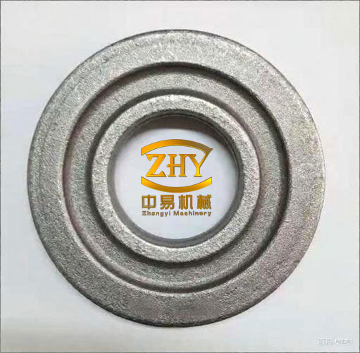
Isothermal normalizing of forged gear blanks. I use isothermal normalizing to convert the as-forged structure into a uniform ferrite-pearlite structure with controlled hardness. The purpose is to improve machinability, reduce residual stress, and provide a consistent starting condition for carburizing. The transformation can be described by a Johnson–Mehl–Avrami–Kolmogorov form:
$$ X(t) = 1 – \exp\left[-k(T)t^n\right] $$
In this expression, X is the transformed fraction, k is a temperature-dependent rate constant, t is time, and n is an exponent related to nucleation and growth. I do not use the equation as a production calculation; I use it to explain why the isothermal hold temperature and time must be controlled. If the hold is too short or the temperature is not uniform, some forged gear blanks retain unstable transformation products or develop mixed structures. If the austenitizing temperature is too high, the prior austenite grain coarsens and the subsequent transformation produces a coarser structure that is difficult to correct.
Hardness uniformity. I measure hardness on a defined map of each forged gear blank and calculate the uniformity index:
$$ U_H = \frac{H_{\max} – H_{\min}}{H_{\mathrm{avg}}} \times 100\% $$
I also compare the same location across a batch. A tight within-part hardness range is necessary but not sufficient; the batch mean must also be stable. If the mean hardness drifts, machining forces and residual stress change, and the soft-machined tooth form will not match the final heat-treated tooth form. I set separate limits for within-part and batch-to-batch hardness variation. For the gear steel family I use, a typical normalized hardness target is in the range of 165–180 HBW, with a within-part range of no more than about 5 HBW and a batch range of no more than about 10 HBW, subject to the specific product requirement. I summarize the normalizing control in Table 3.
| Normalizing parameter | Control target I apply | Effect on forged gear blanks | Verification |
|---|---|---|---|
| Austenitizing temperature | Within a narrow band above the carburizing temperature for the grade | Controls austenite grain size and dissolution of prior structure | Furnace thermocouple survey, batch audit |
| Holding time | Long enough for through-section temperature equalization | Prevents mixed structure and incomplete transformation | Load thermocouples, hardness map |
| Isothermal hold temperature | Selected to produce ferrite-pearlite with target hardness | Sets machinability and dimensional response | Hardness test, metallography |
| Cooling air pattern | Uniform flow across the load; no blocked channels | Reduces hardness scatter in forged gear blanks | Airflow check, load mapping |
| Fixture loading | Defined spacing and support | Controls distortion and cooling uniformity | Loading diagram, first-piece check |
| Hardness range | 165–180 HBW target band | Balances machinability and dimensional stability | Hardness survey per lot |
| Microstructure | Uniform ferrite and pearlite; no overheating; no severe banding | Provides predictable response to carburizing | Metallographic rating |
| Grain size | Within the qualified range for the gear family | Improves toughness and reduces crack risk | Grain size measurement on coupons |
Overheating and abnormal structure. I watch for overheating during normalizing because it is difficult to reverse. An overheated structure has coarse prior austenite grains and may contain Widmanstätten-like or coarse transformation products. Even a subsequent normal cycle may not fully restore the desired grain size if the overheating was severe. The result is lower toughness, higher crack sensitivity, and greater distortion during quenching. I reject forged gear blanks with overheating rather than attempting to normalize them repeatedly. Repeated normalizing adds cost, consumes capacity, and may still leave a structure that behaves differently from the qualified baseline. I also watch for underheating, which can leave remnants of the as-forged structure and produce hardness scatter after normalizing.
The link between normalizing and machining accuracy. I have found that a significant portion of what operators call “machining variation” is actually a normalizing variation. If the hardness of forged gear blanks varies from 160 to 195 HBW within a batch, the cutting tool wears differently, the cutting force changes, and the springback of the fixture changes. The soft-machined tooth profile may look acceptable on the first piece but drift during the batch. I therefore treat normalizing as a precision operation and not as a preliminary step. I require hardness maps, microstructure ratings, and load maps. When the normalizing process is stable, the machining cell can hold a tighter stock allowance, and the heat treatment distortion becomes easier to compensate.
Carburizing and quenching. I identify carburizing and quenching as the most visible source of final tooth distortion, but I always interpret it together with the prior condition of forged gear blanks. The carburizing atmosphere supplies carbon to the surface, and the carbon profile depends on temperature, time, and carbon potential. I use Fick’s second law as the governing diffusion equation:
$$ \frac{\partial C}{\partial t} = D\frac{\partial^2 C}{\partial x^2} $$
For a semi-infinite solid with a constant surface carbon potential, the solution is:
$$ C(x,t) = C_0 + \left(C_s – C_0\right)\left[1 – \mathrm{erf}\left(\frac{x}{2\sqrt{Dt}}\right)\right] $$
Here, C-sub-zero is the initial carbon content, C-sub-s is the surface carbon potential, x is depth, t is time, and D is the diffusion coefficient. The diffusion coefficient depends strongly on temperature:
$$ D = D_0\exp\left(-\frac{Q}{RT}\right) $$
Because of this exponential dependence, a small temperature error can produce a measurable case depth error. I control furnace temperature uniformity and carbon potential uniformity and I verify case depth on test coupons and on representative forged gear blanks. I also control the carburizing time so that the case depth meets the design requirement without excessive austenitizing time. A longer-than-required cycle coarsens the austenite grain and increases distortion risk. I summarize the carburizing and quenching window in Table 4.
| Heat treatment variable | Why I control it | Typical control approach | Accuracy consequence if uncontrolled |
|---|---|---|---|
| Carburizing temperature | Controls diffusion rate and grain growth | Uniformity survey, load thermocouples, batch records | Case depth scatter, grain coarsening, distortion |
| Carbon potential | Controls surface carbon and carbide formation | Atmosphere analysis, oxygen probe, dew point check | Retained austenite scatter, soft spots, grinding cracks |
| Carburizing time | Controls effective case depth | Recipe control, coupon verification | Insufficient case support or excessive case depth |
| Quench temperature | Controls transformation start and thermal gradient | Quench bath temperature control and agitation | Distortion, cracking, hardness scatter |
| Quench intensity | Controls heat transfer and core transformation | Qualified quench medium, agitation mapping, load position | Nonuniform hardness and tooth form change |
| Fixture support | Controls gravity and transformation distortion | Fixtures qualified for each forged gear blank family | Bore ovality, tooth runout, flank twist |
| Tempering temperature | Relieves residual stress and adjusts hardness | Furnace uniformity survey, time-temperature records | Dimensional drift, cracking risk, fatigue loss |
| Tempering time | Allows stress relaxation | Minimum soak time based on section size | Residual stress retained in tooth root |
Case depth and hardness profile. I use a case depth estimate to relate the diffusion equation to inspection:
$$ x_c = \phi\sqrt{Dt} $$
In this expression, x-sub-c is a characteristic case depth and phi is a dimensionless factor selected for the defined case depth criterion. I do not use a single hardness value to judge the case; I use a hardness traverse and a microstructure rating. The surface must have high hardness and wear resistance, while the core must retain sufficient strength and toughness. I specify a fine, uniformly distributed carbide morphology and a controlled retained austenite content. Excessive retained austenite can cause dimensional instability, soft spots, and a change in contact pattern after service or grinding. A controlled amount of retained austenite can improve fatigue resistance, but I treat it as a window, not as “more is better.” I express the retained austenite target as a range and verify it metallographically and by X-ray diffraction where required.
Martensite start temperature and transformation strain. I use the martensite start temperature as an indicator of transformation behavior:
$$ M_s = 539 – 423C – 30.4Mn – 17.7Ni – 12.1Cr – 7.5Mo $$
In this empirical expression, the alloying elements are in weight percent. The equation is approximate, but it shows why small chemistry changes matter. A lower martensite start temperature means more austenite is retained at room temperature, and the transformation strain changes. For axle gears, I want a predictable martensite start temperature across the heat, so I control chemistry and quench temperature together. I also consider the section size of forged gear blanks because the actual cooling rate at the tooth root and in the web determines the local transformation path.
Residual stress and distortion. I describe the residual stress after quenching as a combination of thermal stress and transformation stress:
$$ \sigma_r \approx \frac{E}{1-\nu}\left[\alpha\left(T_{\mathrm{surface}} – T_{\mathrm{center}}\right) + \Delta\varepsilon_{\mathrm{tr}}\right] $$
Here, the first term represents thermal strain mismatch and the second term represents transformation strain mismatch. The two terms can add or partially cancel depending on the steel and the cooling path. I do not attempt to eliminate residual stress completely; instead, I control its distribution and reduce harmful tensile stress at the tooth root and surface. Tempering reduces residual stress approximately according to a relaxation relationship:
$$ \sigma(t) = \sigma_0\exp\left(-\frac{t}{\tau}\right) $$
In this expression, sigma-sub-zero is the initial stress, t is tempering time, and tau is a temperature-dependent relaxation time. The practical conclusion is that a short temper at the wrong temperature may leave unacceptable residual stress even if the hardness is correct. I validate tempering by hardness, microstructure, and distortion stability, not by hardness alone.
Quenching intensity and fixture design. I use quenching intensity as a controlled process variable. If the quench is too severe, the thermal gradient and transformation gradient increase, and the risk of cracking and distortion rises. If the quench is too weak, the case may not achieve the required hardness or the core may not develop sufficient support. I qualify the quench medium, agitation, load spacing, and fixture design together. I pay special attention to the support of forged gear blanks during quenching because unsupported sections can sag or ovalize. The fixture is not a convenience; it is part of the accuracy system. I also control the orientation of forged gear blanks in the load so that the cooling stream reaches the tooth flanks and the bore uniformly.
Distortion modes I measure. I separate distortion into several modes because each mode has a different cause and correction. Tooth profile slope change is often related to nonuniform case depth or bilateral cooling asymmetry. Tooth lead or helix change is often related to fixture support and thermal gradients along the face width. Bore ovality is often related to quenching nonuniformity and section thickness variation. Pitch variation can be related to material banding, nonuniform normalizing, or uneven stock removal. I use a distortion matrix to relate measured modes to likely causes. I summarize the matrix in Table 5.
| Distortion mode | Likely hot processing cause | Process check I perform | Corrective action |
|---|---|---|---|
| Tooth profile slope change | Case depth gradient, carbon potential drift, asymmetric quench | Case depth map, carbon profile, quench flow map | Adjust carbon potential, equalize quench, revise stock allowance |
| Tooth lead or helix change | Fixture support, thermal gradient along face, stacking pattern | Fixture audit, load thermocouple, quench orientation audit | Redesign fixture, change load pattern, modify quenching |
| Bore ovality | Section thickness variation, nonuniform heating or cooling | Bore measurement before and after heat treatment | Balance section, improve fixture, control quench uniformity |
| Pitch variation | Material banding, normalizing scatter, uneven stock removal | Banding rating, hardness map, stock allowance audit | Tighten incoming material, stabilize normalizing, correct machining |
| Tooth thickness change | Transformation strain, retained austenite, tempering drift | Tooth thickness survey, retained austenite measurement | Adjust heat treatment window, correct soft machining offset |
| Runout change | Fixture distortion, residual stress, handling damage | Runout before and after heat treatment, fixture check | Improve support, reduce handling stress, stress relief |
| Root cracking | Corner stress concentration, excessive case carbon, severe quench | Magnetic particle inspection, microstructure check | Reduce carbon potential, modify quench, improve fillet |
Compensation in soft machining. I do not ask heat treatment to hold a tolerance that should be achieved by compensation. I measure the mean distortion of a qualified forged gear blank family and apply a correction to the soft-machined tooth form. The minimum stock allowance is calculated from the expected distortion, machining variation, measurement uncertainty, and a safety margin:
$$ S_{\min} = \delta_{\mathrm{dist,max}} + \delta_{\mathrm{mach}} + \delta_{\mathrm{meas}} + \delta_{\mathrm{safety}} $$
If the stock allowance is too small, the finishing cut may not clean up the distorted surface. If it is too large, the cutting time and tool wear increase, and the residual stress from machining may increase. I use a family-specific allowance and I update it when the heat treatment process or the forged gear blanks source changes. I also measure the soft-machined tooth form, the heat-treated tooth form, and the final ground tooth form as a linked data set. That data set is more useful than any single inspection result because it shows the direction and magnitude of the distortion.
Capability and control. I use process capability indices to judge whether the combined process can hold the gear accuracy requirement:
$$ C_{pk} = \min\left(\frac{USL – \mu}{3\sigma}, \frac{\mu – LSL}{3\sigma}\right) $$
Here, USL and LSL are the upper and lower specification limits, mu is the process mean, and sigma is the process standard deviation. I prefer to evaluate capability before heat treatment and after heat treatment separately, because a process that is capable in the soft state can become incapable after quenching. I also track the mean shift and the variance ratio. A mean shift can be compensated by machining; a variance increase cannot be compensated by a single offset and usually requires a process change. I summarize the capability approach in Table 6.
| Capability indicator | Interpretation I use | Action when below target | Typical data source |
|---|---|---|---|
| Soft-state Cpk | Machining and normalizing stability before heat treatment | Check tool wear, fixture, normalizing hardness uniformity | Soft gear checker, hardness map |
| Heat-treated Cpk | Combined effect of distortion and heat treatment variation | Check quench uniformity, fixture, case depth, retained austenite | Post-heat gear checker, metallography |
| Mean shift | Systematic distortion that can be compensated | Adjust soft machining offset or heat treatment fixture | Paired soft and hard measurements |
| Variance ratio | Random distortion that cannot be corrected by one offset | Reduce process scatter; improve load uniformity | SPC charts by feature |
| Within-part range | Uniformity across the tooth and bore | Improve quench flow, fixture support, furnace uniformity | Map of multiple teeth and positions |
| Batch-to-batch range | Stability of forged gear blanks supply and heat treatment | Audit supplier, re-qualify normalizing and carburizing | Lot traceability and trend charts |
Measurement and datum control. I treat measurement as part of the accuracy chain. If the datum is unstable, the distortion result is not trustworthy. I verify that the gear checker is calibrated, that the part is clean and at a stable temperature, and that the fixture does not deform the part during measurement. I measure the same forged gear blank before and after heat treatment using the same datum scheme where possible. When the datum changes, I document the change and separate the measurement effect from the process effect. I also use a contact pattern check as a functional verification because a gear can pass a dimensional check and still have a poor contact pattern due to heat treatment distortion and assembly deflection.
Thermal process validation. I validate the heat treatment furnace and quench system using a structured system assessment. I verify temperature uniformity, controller accuracy, thermocouple calibration, atmosphere control, quench agitation, and load thermocouples. I also verify the repeatability of the fixture and the loading pattern. I do not accept a furnace survey alone as proof of gear accuracy; the survey must be linked to distortion data from representative forged gear blanks. I use a validation matrix that includes empty-furnace survey, load survey, production trial, first-piece inspection, and ongoing monitoring. Table 7 summarizes the validation elements I require.
| Validation element | What I verify | Frequency | Record used for |
|---|---|---|---|
| Furnace temperature uniformity | All working zones within the qualified band | Initial and periodic | Process qualification |
| Load thermocouple | Part temperature versus controller temperature | During validation and audit | Cycle adjustment |
| Atmosphere control | Carbon potential stability and response time | Daily or per shift | Case depth consistency |
| Quench agitation | Flow pattern and uniformity around the load | Initial and after maintenance | Distortion control |
| Fixture condition | Wear, distortion, and support contact | Per production run | Tooth lead and bore ovality control |
| Distortion trial | Tooth form, lead, pitch, runout before and after heat treatment | New product and process change | Machining compensation |
| Metallurgical verification | Case depth, hardness, microstructure, retained austenite | Per lot or defined frequency | Heat treatment release |
| Supplier change control | Chemistry, forging, normalizing, and grain size consistency | Every supplier or process change | Re-qualification of forged gear blanks |
Interaction between forging and carburizing. I have learned that the final distortion of an axle gear is often determined by the interaction between the forging texture and the carburizing transformation. A forged gear blank with a strong directionality or a nonuniform grain flow can transform differently on one side of the tooth than on the other. The carburizing cycle may be uniform, but the response is not. This is why I qualify the complete route: steel source, forging cell, normalizing furnace, machining cell, carburizing furnace, quench system, and fixture. If I change the forging supplier, I re-qualify the heat treatment even if the chemistry certificate is identical. The reason is that the prior austenite grain size and the internal stress state of forged gear blanks can change without a chemistry change, and those variables affect distortion.
Preventive actions I apply. I use a set of practical controls that have repeatedly improved axle gear accuracy. I tighten incoming material acceptance for grain size, banding, and inclusions. I define a forging temperature window and a post-forging cooling pattern for each forged gear blank family. I require isothermal normalizing with load mapping and hardness mapping. I link the normalizing hardness to the machining stock allowance. I qualify the carburizing and quenching cycle with load thermocouples and distortion trials. I use fixtures that support the gear uniformly and I control the load pattern. I measure distortion by feature and feed it back to soft machining. I do not treat any of these actions as optional; they are part of the precision system. Table 8 summarizes the preventive action plan.
| Preventive action | Accuracy benefit | Key metric | Verification method |
|---|---|---|---|
| Tighten raw material acceptance | Reduces hardenability and transformation scatter | Grain size, banding rating, inclusion rating | Incoming inspection and supplier audit |
| Control forging temperature and cooling | Improves grain flow and structural uniformity of forged gear blanks | Forging temperature, cooling rate, hardness | Temperature records and post-forging inspection |
| Use isothermal normalizing | Stabilizes hardness and machinability | Hardness range and microstructure rating | Hardness map and metallography |
| Couple machining allowance to distortion | Ensures cleanup after heat treatment | Stock allowance and distortion mean shift | Paired soft and hard measurements |
| Qualify carburizing and quenching by load | Reduces case depth and hardness scatter | Case depth, surface hardness, core hardness | Coupons and representative parts |
| Control fixture and load pattern | Reduces tooth lead and bore ovality | Runout, lead change, ovality | Distortion trial and fixture audit |
| Optimize tempering | Relieves residual stress and improves dimensional stability | Hardness and residual stress indicator | Temper audit and stability check |
| Use SPC on critical features | Detects drift before escape | Cpk, mean shift, range | Control charts and capability studies |
A quantitative improvement example. I use a before-and-after comparison to show how the system responds when the hot processing chain is stabilized. In one axle gear family, the initial route had variable normalizing hardness in forged gear blanks and a carburizing load pattern that produced asymmetric tooth lead change. After tightening the normalizing hardness band, improving fixture support, and adjusting the soft machining offset, the mean tooth lead shift decreased and the batch variance decreased. The exact values depend on the gear size and specification, but the pattern is consistent: reduce the variance in forged gear blanks first, then compensate the mean shift in machining, then optimize the quench. Table 9 presents a representative improvement structure that I use for review.
| Metric | Before stabilization | After stabilization | Interpretation |
|---|---|---|---|
| Normalized hardness range in forged gear blanks | Wide batch scatter | Narrow band within the qualified window | More stable machining response |
| Tooth lead mean shift after quenching | Large and directionally biased | Reduced and more centered | Better fixture support and load control |
| Tooth lead standard deviation | High | Lower | Less random distortion |
| Case depth scatter | Broad | Controlled within the specification band | Better atmosphere and temperature uniformity |
| Soft machining stock allowance | Conservative and variable | Optimized and family-specific | Less cutting stress and shorter cycle |
| Final gear accuracy grade | Intermittent nonconformance | Stable within the target grade | Improved system capability |
| Scrap and rework rate | Higher | Lower | Reduced cost and shorter lead time |
My operating rule for forged gear blanks. I never treat forged gear blanks as a generic input. I assign each family a qualified route card that includes the steel hardenability band, forging temperature window, post-forging cooling method, normalizing cycle, hardness target, microstructure limits, carburizing cycle, quench intensity, fixture identification, and soft machining offset. When a nonconformance appears, I check the route card against the actual records before I change the cutting program. In many cases the cutting program is not the root cause; the root cause is a shift in the condition of forged gear blanks or a drift in the normalizing furnace. By protecting the route card, I protect the accuracy of the final gear.
Final inspection and feedback. I close the loop by feeding final inspection data back to the hot processing stages. I do not simply record the final accuracy grade. I break the result into tooth profile, tooth lead, pitch, runout, tooth thickness, and contact pattern. I compare the result with the soft-machined data and the heat treatment records. If the tooth lead changes in a consistent direction, I adjust the fixture or the soft machining offset. If the tooth profile changes randomly, I investigate case depth scatter, carbon potential, quench uniformity, and material banding. If the pitch varies within a single gear, I investigate normalizing uniformity and machining stock distribution. This feedback loop is the practical difference between a heat treatment department and a precision manufacturing system.
Conclusion. I conclude that axle gear accuracy is controlled by the entire hot processing chain, with forged gear blanks as the central carrier of prior structure, residual stress, and dimensional history. The raw material must be clean, fine-grained, and within a controlled hardenability band. The forging of forged gear blanks must produce uniform grain flow and a repeatable cooling history. Isothermal normalizing must deliver a stable hardness and microstructure so that machining removes stock predictably. Carburizing and quenching must be controlled for temperature, carbon potential, case depth, quench intensity, fixture support, and tempering. Soft machining must carry a distortion allowance derived from measured data, not from guesswork. When I apply these controls together, I see lower distortion, tighter tooth form, more stable contact patterns, and fewer escapes. The gear accuracy grade is therefore not only a machining result; it is the visible proof that the hot processing of forged gear blanks has been understood, measured, and controlled.