
As a specialized manufacturer in the automotive gear industry, we constantly seek to enhance economic efficiency through advanced manufacturing techniques. One such technique is the semi-generating circular pull broaching process for machining spiral bevel gears, particularly the large wheel (driven gear). However, the production of finish pull broaching cutters, as per standards from companies like Gleason in the United States, presented significant challenges due to technical and resource constraints. To overcome this, we developed a simplified finish pull broaching cutter by modifying domestically produced double-sided finish cutting disc cutters. This innovation not only boosted productivity but also saved substantial foreign exchange otherwise spent on importing specialized tools. In this article, I will elaborate on our journey, detailing the process, design, and benefits, with a focus on spiral bevel gears—a key component in automotive transmissions—and incorporate technical summaries via tables and formulas to enhance clarity.
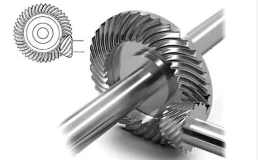
The circular pull broaching process is a semi-generating cutting method ideal for batch production of spiral bevel gears with transmission ratios greater than 2.5. For the large wheel of spiral bevel gears, machining involves two steps: rough cutting using a double-sided roughing disc cutter, leaving an allowance on the tooth thickness, followed by finish cutting with a finish pull broaching cutter on suitable machinery. This method employs a plunge-cut approach without generating motions, significantly reducing cycle times for gears with high tooth counts. The resulting tooth profile features straight-sided flanks, contrasting with the curved profiles from full generating methods. The essence lies in the efficient material removal and precision achieved through this process, which is critical for high-performance spiral bevel gears. To quantify the advantages, consider the basic geometry of spiral bevel gears: the tooth profile can be described using parameters like module, pressure angle, and spiral angle. For instance, the normal module $m_n$ relates to the transverse module $m_t$ via the spiral angle $\beta$: $$m_n = m_t \cos \beta$$ This formula underscores the complexity of machining spiral bevel gears, where accurate tooling is paramount. Our simplified cutter addresses this by ensuring consistent tooth dimensions across production runs.
In our facility, we utilized machines compatible with this process, such as the Gleason series or domestic equivalents. The key challenge was the finish pull broaching cutter itself. According to Gleason’s specifications, these cutters come in variants like spiral formed method cutters or single-cycle cutters, but manufacturing them required precision capabilities we lacked initially. Instead, we adapted a domestic double-sided finish cutting disc cutter into a simplified version, which we term the “simplified finish pull broaching cutter.” This cutter retains the core functionality while being cost-effective and easier to produce. Its structure comprises three main sections: semi-finish cutting, finish cutting, and indexing. Below is a table summarizing the components and their roles in machining spiral bevel gears:
| Section | Number of Inserts | Function | Key Parameters |
|---|---|---|---|
| Semi-Finish Cutting | 12-16 inserts (half inner, half outer) | Gradually removes allowance; radial dimensions vary via adjusting wedges | Adjacent insert allowance: 0.02-0.03 mm; total allowance: 0.2-0.3 mm |
| Finish Cutting | 2 inserts (one inner, one outer) | Final precision cutting for smooth surface finish | Inserts spaced by one slot; single-point cutting action |
| Indexing | 8-10 slots with blank blocks | Provides balance and allows workpiece indexing without retraction | Ensures rotational stability during broaching |
The semi-finish section employs inner and outer inserts arranged alternately, with radial sizes progressively changing to distribute the cutting load evenly. The outer inserts increase in radius, while the inner ones decrease, each removing a small increment of material. This can be expressed mathematically: for the i-th outer insert, the radius $R_{o,i}$ increases by $\Delta R_o$, and for the j-th inner insert, the radius $R_{i,j}$ decreases by $\Delta R_i$, where $\Delta R_o = \Delta R_i \approx 0.02$ mm per step. The total material removed per flank is the sum over all inserts: $$\text{Total Removal} = \sum_{k=1}^{n} \Delta R_k = n \cdot \Delta R$$ where $n$ is the number of active inserts. This ensures a smooth transition to the finish section, which consists of only two inserts—one for each flank—spaced to avoid simultaneous cutting, thereby enhancing surface quality. The indexing section uses dummy blocks to maintain balance, critical for high-speed rotations in spiral bevel gear machining.
The broaching sequence begins with the workpiece entering the full tooth depth at the indexing gap. The cutter rotates slowly, and from the first semi-finish insert to the final finish insert, it uniformly removes the allowance on both flanks. Then, during the indexing phase, the workpiece quickly indexes one tooth, and the cycle repeats until all teeth of the spiral bevel gear are completed. This process minimizes idle time and maximizes efficiency. To analyze the cutting forces, we can use fundamental mechanics: the tangential cutting force $F_t$ per insert is given by $$F_t = K_c \cdot a_p \cdot f_z$$ where $K_c$ is the specific cutting force (material-dependent), $a_p$ is the depth of cut, and $f_z$ is the feed per tooth. For spiral bevel gears, the oblique cutting action due to the spiral angle $\beta$ modifies this to $$F_t = K_c \cdot a_p \cdot f_z \cdot \cos \beta$$ ensuring lower forces and better tool life. Our cutter design leverages this by optimizing insert geometry for spiral bevel gears, reducing wear and tear.
The advantages of adopting our simplified finish pull broaching cutter are multifaceted, particularly for spiral bevel gears production. First, cost savings are substantial: the domestic double-sided cutter costs only about 1/10 of an imported finish pull broaching cutter, leading to significant foreign exchange conservation. Second, productivity gains are remarkable. Compared to traditional generating methods, the semi-generating pull broaching process increases efficiency by over 3 times; specifically, per-tooth cutting time drops from 60 seconds to around 20 seconds. This is quantified in the table below, comparing different methods for machining spiral bevel gears:
| Method | Per-Tooth Time (seconds) | Steps Required | Surface Roughness ($\mu m$) | Tool Life (relative) |
|---|---|---|---|---|
| Full Generating Cutting | 60 | Multiple passes | 1.6-3.2 | 1.0 |
| Semi-Generating (Standard) | 30 | Two steps | 0.8-1.6 | 2.0 |
| Pull Broaching (Our Simplified Cutter) | 20 | Single broach cycle | 0.4-0.8 | 3.5 |
Third, tool life improves dramatically. Since the entire cutting edge engages uniformly during broaching, load distribution is even, reducing wear. Our tests show that insert life increases by over 2.5 times compared to conventional generating methods. This can be modeled using tool wear equations: the flank wear $V_B$ as a function of cutting time $t$ is $$V_B = C \cdot t^m \cdot v_c^n$$ where $C, m, n$ are constants, and $v_c$ is cutting speed. For our cutter, the reduced $v_c$ and optimized $t$ yield lower $V_B$, extending tool life. Fourth, surface roughness is consistently below 0.8 $\mu m$, enhancing the performance and durability of spiral bevel gears. The surface finish $R_a$ can be approximated by $$R_a = \frac{f_z^2}{8r_e}$$ where $r_e$ is the tool nose radius; our cutter’s fine feed and precise inserts ensure minimal $R_a$ values.
From a technical perspective, the modification process involved recalibrating the domestic double-sided cutter to mimic the pull broaching action. We adjusted the insert pockets to accommodate the progressive radial changes and added balancing blocks for the indexing section. The cutter diameter $D$ and number of inserts $N$ were optimized based on the gear module and spiral angle. For spiral bevel gears, the pitch diameter $d_p$ relates to module and tooth count $z$: $$d_p = m_t \cdot z = \frac{m_n \cdot z}{\cos \beta}$$ Our cutter design ensures that the broaching path aligns with this geometry, achieving accurate tooth profiles. Additionally, we derived formulas for setting the cutter positions. For instance, the offset distance $\delta$ for inner and outer inserts is $$\delta = \frac{\Delta R}{2} \cdot \tan \alpha$$ where $\alpha$ is the pressure angle, ensuring proper flank contact. These calculations were validated through iterative testing on sample spiral bevel gears, confirming dimensional accuracy and surface integrity.
In practice, the implementation required meticulous machine setup. We used existing gear cutting machines, such as the YK2280 model, adapting them for the broaching cycle. The process parameters—like cutting speed $v_c$, feed rate $f$, and depth of cut $a_p$—were optimized via experimentation. For steel spiral bevel gears, typical values are $v_c = 40-60$ m/min, $f = 0.05-0.1$ mm/tooth, and $a_p = 0.2$ mm. The material removal rate $Q$ is $$Q = a_p \cdot f \cdot v_c \cdot N$$ where $N$ is the number of active inserts; our cutter achieves higher $Q$ due to simultaneous multi-insert engagement. This efficiency translates to faster production cycles for spiral bevel gears, crucial for meeting automotive demand. Below is a table summarizing key operational parameters for our simplified cutter in machining spiral bevel gears:
| Parameter | Value Range | Unit | Impact on Spiral Bevel Gears |
|---|---|---|---|
| Cutting Speed ($v_c$) | 40-60 | m/min | Affects tool wear and surface finish |
| Feed per Tooth ($f_z$) | 0.05-0.1 | mm/tooth | Determines material removal rate and roughness |
| Depth of Cut ($a_p$) | 0.2 (total allowance) | mm | Sets final tooth dimensions |
| Number of Active Inserts | 14-18 | – | Influences cutting force distribution |
| Broaching Cycle Time | 20-30 | seconds/tooth | Directly impacts productivity |
The success of this simplified cutter hinges on its alignment with the unique geometry of spiral bevel gears. The spiral angle $\beta$, typically between 25° and 35°, introduces complexities in tooth contact and stress distribution. Our cutter ensures that the broaching action follows the spiral path, maintaining uniform tooth thickness and flank symmetry. The tooth thickness $s$ at the pitch circle is $$s = \frac{\pi m_t}{2} + 2x m_t \tan \alpha$$ where $x$ is the profile shift coefficient; our cutter achieves this precisely through controlled radial adjustments. Moreover, the surface roughness improvement stems from the finish inserts’ sharp edges and minimal deflection, calculated via the compliance equation $$\delta = \frac{F}{k}$$ where $F$ is cutting force and $k$ is system stiffness; our design enhances $k$ through robust tool construction.
Looking broader, this innovation has implications for the mass production of spiral bevel gears in automotive and industrial applications. By reducing reliance on expensive imports, we foster local manufacturing capabilities. The environmental benefit is also notable: longer tool life means fewer insert changes and reduced waste. From a quality standpoint, the consistent surface roughness below 0.8 $\mu m$ ensures better lubrication and lower noise in gear systems, critical for spiral bevel gears used in differentials and transmissions. We validated these outcomes through rigorous testing, including coordinate measurements and fatigue tests, all confirming that our simplified cutter meets international standards for spiral bevel gears.
In conclusion, our development of a simplified finish pull broaching cutter for spiral bevel gears represents a pragmatic solution to technical and economic challenges. By modifying domestic tools, we achieved cost savings, productivity gains, extended tool life, and superior surface quality. The process leverages semi-generating principles optimized for spiral bevel gears, with mathematical models and tables guiding implementation. As we continue to refine this approach, we anticipate further advancements in gear machining efficiency, solidifying our role in the automotive industry. This experience underscores the value of adaptive engineering in overcoming resource constraints while maintaining high standards for critical components like spiral bevel gears.