
I designed this fixture around a practical production problem: a steering-gear rocker shaft has a complex shaft body and a sector-tooth form, and the final tooth profile must be produced by gear shaping after rough milling. When I rely on manual positioning and manual clamping, the operator has to hold the part, estimate the angular position of the sector, tighten a clamp, and then verify the tooth allowance. That sequence is slow, and it introduces variation into the gear shaping operation. My objective was therefore to create a dedicated fixture for a CNC gear shaping machine that uses a spring collet for centering, a hydraulic cylinder for clamping power, and a removable locating plate for angular orientation. The fixture must hold the shaft rigidly during gear shaping, keep the sector-tooth allowance uniform, and allow changeover to different rocker-shaft sizes by replacing a small number of elements.
The workpiece is a forged shaft made of 20CrMnTiH3. Its long shaft and short shaft carry high loads and require reliable sealing; the sector teeth in the middle region have a high accuracy requirement. The sector tooth tip is a conical surface, so the cross-section of the sector changes along the axis. This means that the modification coefficient is different at each axial section, and the gear shaping cutter must work with its main reciprocating direction at a defined angle to the workpiece axis. For the zero-modified section, the tip arc radius is specified as R56.22 with a single-part variation not greater than 0.025 mm. The effective tip radius used in my force estimate is 55.25 mm, the full-circle tooth count is 11, the module is 8.5 mm, and the nominal addendum is 6.8 mm. These values drive both the locating scheme and the clamping-force calculation.
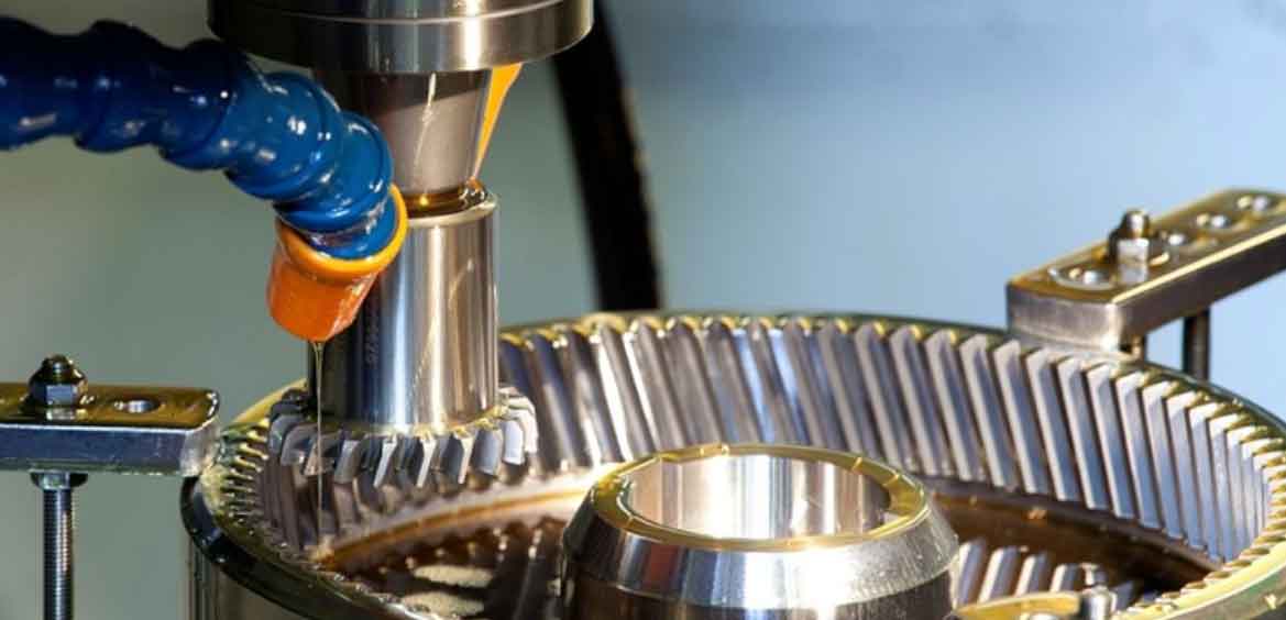
My Design Requirements and Workpiece Data
I began by translating the drawing requirements into fixture requirements. The long shaft outer diameter is the natural centering datum because the sector teeth have a position relationship with the long and short shaft journals. If I center on the long shaft, the gear shaping allowance around the sector is controlled by the same datum that will later be used for finish grinding. The sector step face gives me a clean axial datum. The two side faces of the forged sector give me a reliable angular datum because they are already formed before gear shaping. I therefore chose a full six-degree-of-freedom locating scheme rather than a partial scheme.
| Item | Value or Requirement | Why It Matters in My Fixture |
|---|---|---|
| Workpiece material | 20CrMnTiH3 | High strength and case-hardening behavior require rigid clamping during gear shaping. |
| Main feature | Long shaft, short shaft, sector teeth | The long shaft is the centering datum; the sector faces are the angular datum. |
| Sector tooth form | Conical tip surface | The tooth cross-section varies along the axis, so angular orientation must be repeatable. |
| Zero-modified section | R56.22, variation not greater than 0.025 mm | This is the key accuracy target for gear shaping. |
| Module | 8.5 mm | Used in gear shaping force and torque estimates. |
| Full-circle tooth count | 11 | Used to describe the sector geometry and cutter indexing. |
| Nominal addendum | 6.8 mm | Used with the effective tip radius in the torque calculation. |
| Effective tip radius for force estimate | 55.25 mm | Converts the tangential cutting force into a torque on the workpiece. |
| Long shaft clamping diameter | 55 mm after preparation | The spring collet must grip this surface without marking or slipping. |
| Zero-section axial distance from step face | 5 mm | The step face is my axial locating datum. |
| Production mode | Batch production with multiple rocker-shaft variants | I need group machining by changing the collet and cone sleeve. |
Process Route and My Locating Logic
The manufacturing route follows the principle that the datum surface is prepared before the accuracy-critical operation. I first mill both end faces and drill the center holes. Those center holes support later turning and grinding between centers. I then rough-turn the sector side faces and top face, the short shaft outer diameter, and the long shaft outer diameter. Next I semi-finish the short shaft, drill and bore the short-shaft end hole, and cut the thread. I semi-finish the long shaft and the sector, rough-mill the sector teeth, perform semi-finish gear shaping and finish gear shaping, and then roll the involute spline on the long shaft end. After heat treatment, I lap the center holes and finish-grind the long and short shaft outer diameters. The gear shaping operation is therefore not an isolated step; it must preserve the position relationship between the sector teeth and the shaft journals.
| Stage | Operation | Datum or Purpose |
|---|---|---|
| 1 | Mill end faces and drill center holes | Prepare the center-hole datum for turning and grinding. |
| 2 | Rough-turn sector side and top, short shaft, long shaft | Establish the main shaft surfaces and approximate sector envelope. |
| 3 | Semi-finish short shaft, drill and bore end hole, cut thread | Complete the short-shaft end features before gear shaping. |
| 4 | Semi-finish long shaft and sector | Provide a stable clamping surface and uniform gear shaping allowance. |
| 5 | Rough-mill sector teeth | Remove most material before gear shaping. |
| 6 | Semi-finish gear shaping | Establish the tooth form with a controlled allowance. |
| 7 | Finish gear shaping | Reach the final sector-tooth accuracy. |
| 8 | Roll the involute spline | Form the long-shaft spline after gear shaping. |
| 9 | Heat treatment, lap center holes, finish-grind shafts | Finalize shaft accuracy and preserve the gear shaping datum relationship. |
My locating scheme is simple but complete. The long shaft outer diameter limits four degrees of freedom: two translations in the radial plane and two rotations about the radial axes. The sector step face limits one axial translation. The two sector side faces, acting through two locating pins on a removable plate, limit the rotation about the shaft axis. This gives six degrees of freedom in total. The long shaft centering follows the datum-coincidence principle because the same long shaft axis is the position reference for the sector teeth. The step face is also a datum-coincidence choice because the zero-modified section is defined at a fixed distance from that face. The sector side faces are used in both rough milling and gear shaping, so the angular datum is unified between the two operations.
| Locating Element | Workpiece Surface | Degrees of Freedom Removed | My Reason |
|---|---|---|---|
| Spring collet | Long shaft outer diameter | Radial translation in two directions and two radial rotations | Centers the shaft and aligns the gear shaping axis with the shaft axis. |
| Locating end cap and step face | Sector step face | Axial translation | Fixes the zero-modified section position relative to the fixture. |
| Two locating pins on removable plate | Sector side faces | Rotation about the shaft axis | Sets the sector symmetry plane and equalizes gear shaping allowance. |
Overall Fixture Architecture
I arranged the fixture as a compact stack on the CNC gear shaping machine table. The fixture base is bolted to the machine table. A cone sleeve is located in the base bore by a close clearance fit and fixed with screws. The spring collet has an external cone that matches the cone sleeve. Its lower end is connected to the hydraulic cylinder piston rod through a radial pin, so the cylinder can pull the collet downward. A locating end cap closes the upper end of the cone sleeve and provides the axial stop. The removable locating plate carries two pins and a key slot; the key slot slides over a key on the locating end cap. The operator installs the plate, brings both pins into contact with the sector side faces, clamps the workpiece, and then removes the plate before gear shaping so that the cutter has clear access.
| Fixture Element | Function in My Design | Key Design Point |
|---|---|---|
| Fixture base | Carries the cone sleeve and connects to the machine table | Rigid mounting and a clean bore for the cone sleeve |
| Cone sleeve | Provides the internal conical surface for collet contraction | Internal cone matched to the collet; contact area checked by bluing |
| Spring collet | Centers and clamps the long shaft | Elastic petals contract uniformly when pulled downward |
| Locating end cap | Closes the upper end and provides the axial stop and key | Key guides the removable locating plate |
| Removable locating plate | Carries two pins for angular orientation | U-shaped slot clears the short shaft; key slot controls plate position |
| Two locating pins | Contact the sector side faces | Define the sector symmetry plane for uniform gear shaping allowance |
| Hydraulic cylinder | Provides axial pulling force | Pull rod connected to the collet tail by a radial pin |
| Stop screw and stop slot | Limit collet travel | Prevents excessive clamping force and collet overload |
Spring Collet Design and Cone Geometry
The spring collet is the heart of my centering system. Unlike a standard collet that is tightened by a nut, my collet is pulled downward by the hydraulic cylinder. The tail of the collet therefore has a connection feature for the piston rod. A radial pin passes through the tail outer circle and transfers the pulling force. When the collet moves downward relative to the cone sleeve, the petals contract inward and clamp the long shaft. The half-cone angle is 7.5 degrees, so the included cone angle is 15 degrees. The internal bore of the cone sleeve and the external cone of the collet are finish-matched to each other. I specify that the 15-degree cone contact is checked by color transfer, with contact area greater than 80 percent, and that the cone bore is coaxial with its mounting datum within 0.01 mm.
For a small axial displacement of the collet, the radial contraction is governed by the cone angle. I use the following relation to estimate the radial movement:
$$ \delta_r = \delta_a \tan \alpha $$
where $$\delta_r$$ is the radial contraction of the collet petals, $$\delta_a$$ is the axial displacement of the collet relative to the cone sleeve, and $$\alpha$$ is the half-cone angle. For my design, $$\alpha = 7.5^\circ$$. This relation tells me that the axial stroke must be controlled carefully. If the axial stroke is too large, the radial clamping force rises quickly and the collet may be overstressed. That is why I add a stop slot and a stop screw. The stop screw enters the slot from the fixture base and limits the downward travel of the collet.
The spring collet must also be sized for different shaft diameters. The clamping bore is matched to the long shaft outer diameter. For one representative variant, the collet bore at the clamping zone is 51.1 mm, while the mating shaft surface in the fixture is prepared to the required nominal size for that variant. I do not use one collet for all variants. Instead, I treat the collet as a changeable group-machining element. The cone sleeve can remain common if the external collet cone is kept in a standard family, or it can also be changed when the stiffness requirement changes.
| Spring Collet Parameter | Value or Rule | Effect on Gear Shaping |
|---|---|---|
| Half-cone angle | 7.5 degrees | Provides self-centering contraction with manageable axial stroke. |
| Included cone angle | 15 degrees | Matches the cone sleeve and is checked by contact pattern. |
| Collet tail connection | Radial pin to piston rod | Transfers hydraulic pull without a rotating nut. |
| Contact area of cone | Greater than 80 percent by color check | Ensures uniform petal contraction and repeatable centering. |
| Coaxiality of cone bore to datum | 0.01 mm | Limits eccentricity that would disturb gear shaping allowance. |
| Stop feature | Stop slot with base-mounted screw | Prevents excessive pull and collet fatigue. |
| Representative collet bore | 51.1 mm for one variant | Allows group machining by replacing the collet. |
Cutting Force and Clamping Force Calculation
I calculated the clamping force for the worst case in the gear shaping cycle. The operation is divided into semi-finish gear shaping and finish gear shaping. Semi-finish gear shaping removes more material and therefore produces the larger cutting force. The semi-finish parameters are cutting speed 204 m/min, feed 0.33 mm per stroke, and depth of cut 2.5 mm. The finish parameters are cutting speed 245 m/min, feed 0.28 mm per stroke, and depth of cut 0.85 mm. Because the semi-finish pass dominates, I used it for the clamp design.
| Gear Shaping Pass | Cutting Speed (m/min) | Feed (mm/stroke) | Depth of Cut (mm) | Use in My Calculation |
|---|---|---|---|---|
| Semi-finish gear shaping | 204 | 0.33 | 2.5 | Worst case for clamping force |
| Finish gear shaping | 245 | 0.28 | 0.85 | Lower cutting load, used for final accuracy |
The nominal cross-sectional area of the cutting layer is:
$$ A_D = a_p f $$
$$ A_D = 2.5 \times 0.33 = 0.825\ \mathrm{mm^2} $$
Using the unit cutting force and the correction factors for the working conditions, I obtain the main cutting force and the feed force:
$$ F_c = k_c A_D K_c $$
$$ F_c \approx 2153\ \mathrm{N} $$
$$ F_f \approx 861\ \mathrm{N} $$
Here $$F_c$$ is the main cutting force, which acts in the axial direction of the gear shaping cutter, and $$F_f$$ is the feed force, which acts tangentially. The radial force is directed toward the workpiece center. Because the spring collet is a closed-ring centering element, the radial force is balanced by the collet and does not create a tendency for the workpiece to slide out of the collet. The tangential force, however, creates a torque about the shaft axis, and the axial force tends to push the workpiece along the shaft axis. I therefore check the clamping force against both the torque and the axial force.
| Quantity | Symbol | Value | My Interpretation |
|---|---|---|---|
| Unit cutting force | $$k_c$$ | 1962 N/mm² | Material-dependent cutting resistance |
| Cutting-layer area | $$A_D$$ | 0.825 mm² | Product of depth of cut and feed |
| Main cutting force | $$F_c$$ | 2153 N | Axial load on the workpiece and fixture |
| Feed force | $$F_f$$ | 861 N | Tangential load that creates torque |
| Effective tip radius | $$r_a$$ | 55.25 mm | Lever arm for the torque estimate |
| Clamping friction coefficient | $$f$$ | 0.15 | Collet-to-workpiece friction |
| Safety factor | $$K$$ | 1.8 | Accounts for variation in cutting and clamping |
| Clamped shaft radius | $$r$$ | 27.5 mm | Radius of the long shaft clamping surface |
The torque produced by the feed force about the shaft axis is:
$$ M_e = F_f r_a $$
$$ M_e = 861 \times 0.05525 = 47.57\ \mathrm{N\cdot m} $$
To prevent the workpiece from rotating in the collet during gear shaping, the friction torque must exceed the cutting torque with a safety margin. I use the standard form for the required radial clamping force when the collet has axial support:
$$ F = \frac{K M_e}{f r} $$
$$ F = \frac{1.8 \times 47.57}{0.15 \times 0.0275} \approx 20757\ \mathrm{N} $$
This is the radial clamping force that the collet must develop on the long shaft. The collet petals also have their own elastic resistance. I estimate the elastic force per petal as 474 N. The axial force required from the hydraulic cylinder is then obtained from the cone friction balance:
$$ Q = (F + R_c)\tan(\alpha + \rho_1) + F\tan\rho_2 $$
where $$R_c$$ is the elastic resistance of the collet petals, $$\rho_1$$ is the friction angle between the collet and the cone sleeve, and $$\rho_2$$ is the friction angle between the collet and the workpiece. I use $$\rho_1 = 11.5^\circ$$, $$\rho_2 = 8.5^\circ$$, and $$\alpha = 7.5^\circ$$. Substituting the values gives:
$$ Q = (20757 + 474)\tan(7.5^\circ + 11.5^\circ) + 20757\tan 8.5^\circ $$
$$ Q \approx 10412\ \mathrm{N} $$
Therefore, my hydraulic cylinder must provide an axial pull of about 10.41 kN. I selected a pull-rod hydraulic cylinder with a rated pressure of 3.5 MPa and a bore of 80 mm. The theoretical thrust at rated pressure is approximately 17.6 kN, and with a cylinder efficiency of 0.8 the usable thrust is still above 14 kN. This gives a comfortable margin over the required 10.41 kN. The margin is useful because friction can rise if the cone surfaces are not perfectly lubricated, and because the collet may need extra force when the long shaft diameter is at the upper tolerance limit.
| Check | Required or Calculated Value | Selected or Available Value | Result |
|---|---|---|---|
| Radial clamping force | $$F = 20757\ \mathrm{N}$$ | Developed by collet contraction | Design target |
| Axial pull force | $$Q = 10412\ \mathrm{N}$$ | Cylinder usable thrust greater than 14 kN | Accepted |
| Cylinder rated pressure | 3.5 MPa | 3.5 MPa | Matches selection |
| Cylinder bore | 80 mm | 80 mm | Provides sufficient area |
| Cylinder efficiency | 0.8 | 0.8 | Used in usable-thrust estimate |
| Torque from feed force | 47.57 N·m | Friction torque must exceed this value | Covered by clamping force |
Clamping Mechanics and Release Behavior
My clamping sequence is hydraulic pull and spring release. When the cylinder is not pressurized, the collet is in the relaxed state, and its upper end face is approximately flush with the cone sleeve end face. In this state the long shaft can be inserted by hand. When the cylinder pulls the collet downward, the external cone slides inside the cone sleeve. The petals contract and center the long shaft. Because the collet is pulled rather than pushed, the hydraulic force acts in the same direction as the collet contraction, which makes the mechanism compact and direct. The stop screw limits the maximum downward travel. I set the stop position so that the collet can still generate the required clamping force but cannot be forced so far that the petals yield or the cone sleeve is overloaded.
The release behavior is equally important for production. When the cylinder pressure is removed, the elastic energy stored in the collet petals helps the collet return to its relaxed position. I keep the cone contact surfaces clean and lightly lubricated so that the collet does not stick in the clamped position. The radial pin connection between the collet tail and the piston rod prevents the collet from rotating during release. This is important because the locating plate and pins depend on a repeatable angular relationship between the workpiece and the fixture. The collet itself is rotationally symmetric, but the workpiece is not. The angular orientation is set by the locating plate before clamping, and the collet must not disturb that orientation while it contracts.
| Phase | Collet State | Workpiece State | Operator Action |
|---|---|---|---|
| Load | Relaxed, upper face near flush | Inserted by hand | Place the long shaft into the collet |
| Angular locate | Relaxed | Free to rotate slightly | Slide the locating plate in and bring both pins to the sector side faces |
| Clamp | Pulled downward and contracted | Centered and held | Actuate the hydraulic cylinder |
| Prepare for gear shaping | Clamped | Held in the correct angular position | Remove the locating plate to clear the cutter path |
| Release | Returns elastically | Released | Remove the finished part |
Locating Plate and Angular Orientation
The angular orientation is the part of the fixture that most directly protects the gear shaping allowance. The locating plate has a U-shaped slot that clears the short shaft, and it carries two symmetrically arranged pins. The plate has a key slot on its bottom face, and the locating end cap has a matching key. The operator slides the plate from one side until the key slot fully engages the key. At that point the two pins are in the correct angular position relative to the fixture. The operator then brings the two pins into contact with the two side faces of the sector. This contact defines the symmetry plane of the sector. After the collet clamps the workpiece, the plate is withdrawn. The withdrawal is necessary because the plate would otherwise be in the path of the gear shaping cutter.
I use two pins rather than one because the sector has two side faces. One pin alone would define only one side and would not control the symmetry plane. Two pins in contact with the two side faces force the sector to sit symmetrically about the fixture center plane. This is the key to uniform gear shaping allowance on both sides of the sector. The locating plate is not a clamp. It is a setting gage that is removed before cutting. This separation between locating and clamping is deliberate. If the plate remained in place during gear shaping, the cutting forces and the cutter motion could load the plate and cause it to deflect or interfere with the gear shaping cutter.
| Feature | Design Choice | Reason |
|---|---|---|
| Plate slot | U-shaped clearance for the short shaft | Allows the plate to slide in from the side while the shaft is vertical |
| Key and key slot | Matching rectangular key on end cap | Positions the plate relative to the fixture before the pins touch the sector |
| Two locating pins | Symmetric contact with sector side faces | Defines the sector symmetry plane |
| Removal before cutting | Plate is withdrawn after clamping | Prevents interference with the gear shaping cutter |
| Pin contact | Line or small-area contact on forged side faces | Provides a clear seating feeling for the operator |
Operation Sequence for Gear Shaping
I wrote the operating sequence so that the locating plate and the hydraulic clamp are used in the correct order. The workpiece must be free to rotate slightly when the locating plate is engaged. If the collet is clamped first, the friction between the collet and the long shaft may prevent the small angular adjustment needed to bring both pins into contact with the sector side faces. Therefore, the correct order is: insert the workpiece, engage the locating plate, actuate the clamp, remove the plate, and start gear shaping. This order also prevents the operator from forcing the sector against the pins while the collet is already gripping the shaft.
| Step | Operation | Critical Point |
|---|---|---|
| 1 | Clean the collet bore and the long shaft clamping surface | Friction and centering repeatability depend on clean surfaces |
| 2 | Insert the long shaft into the collet until the step face contacts the axial stop | The zero-modified section is fixed relative to the fixture |
| 3 | Slide the locating plate along the key until the two pins touch the sector side faces | Do not force the plate; the workpiece may rotate slightly |
| 4 | Actuate the hydraulic cylinder to pull the collet | The collet centers and clamps the long shaft |
| 5 | Verify that the workpiece is held and the step face is seated | Prevents axial mislocation before gear shaping |
| 6 | Withdraw the locating plate | Clears the gear shaping cutter path |
| 7 | Run semi-finish gear shaping | Use the semi-finish cutting parameters |
| 8 | Run finish gear shaping | Use the finish cutting parameters |
| 9 | Release the hydraulic clamp and remove the part | Inspect the sector tooth allowance and surface |
Changeover and Group Machining
The rocker-shaft family contains several shaft diameters and sector sizes. I do not want a completely new fixture for each variant. My approach is to keep the fixture base, hydraulic cylinder, locating end cap, and locating plate mechanism common, while changing the spring collet and, when necessary, the cone sleeve. The collet bore is matched to the long shaft diameter. The cone sleeve is matched to the collet external cone. The locating plate pin spacing and pin diameter are matched to the sector side-face geometry. This gives a practical group-machining system: a small set of change parts covers a family of workpieces, and the gear shaping machine does not need a new fixture for every product change.
| Variant Feature | Common Element | Changed Element | Changeover Check |
|---|---|---|---|
| Long shaft diameter | Fixture base and hydraulic pull rod | Spring collet bore | Check radial clearance and clamping force |
| Collet external cone | Hydraulic pull system | Cone sleeve if the cone family changes | Check 15-degree contact pattern |
| Sector side-face spacing | Locating plate body and key | Pin spacing or pin diameter | Check two-pin contact and symmetry |
| Axial step-face position | Locating end cap | Axial stop shim or cap height | Check zero-section distance |
| Gear shaping stroke clearance | Machine table and fixture base | Collet length if required | Check cutter clearance before production |
For one representative variant, the collet bore is 51.1 mm. I treat this as a family member rather than as a universal size. The collet wall thickness and petal length are selected so that the collet can contract enough to clamp the shaft without exceeding the elastic limit. The cone sleeve is finish-machined after heat treatment, and the final cone contact is matched to the collet. I prefer to match the collet and cone sleeve as a pair because the contact pattern directly affects centering accuracy and clamping stiffness. If a collet is replaced without checking the contact pattern, the radial clamping force may be uneven, and the workpiece may tilt slightly during gear shaping.
Accuracy, Repeatability, and Quality Control
The accuracy of the gear shaping operation depends on three things in my fixture: centering accuracy, axial seating accuracy, and angular repeatability. Centering accuracy is controlled by the spring collet and cone sleeve. Axial seating accuracy is controlled by the step face and locating end cap. Angular repeatability is controlled by the locating plate key and two pins. I do not rely on the operator’s feel for the final tooth position. The operator uses the plate to set the sector symmetry plane, and the hydraulic clamp preserves that position. The gear shaping cutter then removes the allowance from both sides of the sector.
The radial centering error caused by axial collet displacement can be estimated from the cone relation:
$$ \Delta r = \Delta a \tan \alpha $$
where $$\Delta r$$ is the radial centering error and $$\Delta a$$ is the axial positioning error of the collet. Because $$\alpha = 7.5^\circ$$, the radial error is much smaller than the axial error. This is one reason I use a shallow cone. A shallow cone gives fine radial adjustment for a given axial stroke, but it also means that the axial stroke must be controlled. The stop screw and the hydraulic cylinder stroke provide that control. The cone contact check and the coaxiality requirement of 0.01 mm keep the centering error within the allowance of the gear shaping operation.
| Quality Item | Control Method | Acceptance Criterion | Effect on Gear Shaping |
|---|---|---|---|
| Collet-to-cone contact | Color transfer check | Greater than 80 percent contact | Uniform petal contraction and stable clamping |
| Cone bore coaxiality | Measurement relative to mounting datum | 0.01 mm | Limits eccentricity of the shaft axis |
| Axial step-face seating | Visual and feeler check before clamping | No gap at the step face | Fixes the zero-modified section position |
| Angular plate engagement | Key slot fully engaged before pin contact | Both pins touch the sector side faces | Equalizes gear shaping allowance |
| Clamping force | Hydraulic pressure setting and stop position | Above 10.41 kN axial pull | Prevents slip during gear shaping |
| Plate removal | Operator checklist before cycle start | Plate clear of cutter path | Avoids interference and damage |
I also use the gear shaping operation itself as a check on the fixture. If the sector allowance is not uniform after semi-finish gear shaping, the angular locating plate or the axial stop is not seating correctly. If the tooth profile shows a periodic error, the collet may not be contracting uniformly, or the cone contact may be poor. If the workpiece slips during gear shaping, the clamping force is insufficient or the collet bore is worn. These symptoms are easy to separate because the fixture has distinct locating and clamping functions. The locating plate sets the angle, the step face sets the axial position, and the collet sets the radial center. Each function can be checked independently.
Comparison with Manual Positioning and Clamping
Manual positioning and clamping is the baseline I wanted to replace. In the manual method, the operator holds the workpiece, aligns the sector by eye or with a simple gage, and tightens a mechanical clamp. The clamp force depends on the operator, the tightening torque, and the friction of the thread. The gear shaping cutter then cuts with a force that can push the workpiece if the clamp is not tight enough. This method is slow, and the result varies from part to part. My hydraulic spring-collet fixture removes the manual tightening step. The operator only inserts the part, engages the locating plate, and presses the clamp control. The hydraulic cylinder provides a repeatable axial pull, and the spring collet provides a repeatable radial centering force.
| Comparison Item | Manual Positioning and Clamping | My Hydraulic Spring-Collet Fixture |
|---|---|---|
| Centering method | Operator aligns by eye or simple gage | Spring collet centers on the long shaft |
| Angular location | Manual estimate or loose block | Two pins and keyed locating plate define the sector symmetry plane |
| Clamp force | Depends on operator torque | Hydraulic cylinder provides repeatable axial pull |
| Cycle time | Long manual tightening and checking | Short hydraulic clamp and release |
| Repeatability | Low to moderate | High, because the locating and clamping functions are separated |
| Automation level | Low | High, suitable for CNC gear shaping |
| Changeover | New fixture or extensive adjustment | Change collet, cone sleeve, and locating plate |
| Gear shaping allowance | Can be uneven | Controlled by the sector symmetry plane |
Maintenance, Safety, and Production Discipline
I treat maintenance as part of the fixture design. The cone surfaces must be kept clean because chips or dried coolant can change the friction angle and the clamping force. The collet bore must be free of burrs because a burr can mark the long shaft or prevent full seating. The locating pins must be checked for wear because worn pins change the angular position of the sector. The stop screw must be locked after adjustment because a change in the stop position changes the collet travel and the clamping force. The hydraulic connections must be checked for leakage because a pressure drop during gear shaping can release the workpiece. These checks are simple, but they protect the gear shaping accuracy and the safety of the operator.
| Maintenance Item | Frequency | Check | Corrective Action |
|---|---|---|---|
| Collet bore and cone | Each shift | Cleanliness and freedom from burrs | Clean and replace if worn |
| Cone contact pattern | At changeover or periodic inspection | Greater than 80 percent contact | Rematch or replace collet and sleeve |
| Locating pins | Each shift | Wear and secure mounting | Replace worn pins |
| Stop screw | After adjustment | Locked position | Lock securely |
| Hydraulic pressure | Each shift | Rated pressure and no leakage | Repair leakage and reset pressure |
| Locating plate key | Each shift | Free sliding and full engagement | Clean and deburr |
| Gear shaping cutter clearance | Before production | No interference with plate or fixture | Remove plate and adjust setup |
My Final Assessment
I consider the design successful because it solves the specific problem of gear shaping a complex rocker shaft without relying on manual tightening. The long shaft outer diameter provides a reliable centering datum, the sector step face provides a clean axial datum, and the two sector side faces provide a repeatable angular datum. The spring collet converts a hydraulic axial pull into a uniform radial clamping force. The cone sleeve and collet are matched to ensure contact and coaxiality. The locating plate is removable, so it does not interfere with gear shaping. The hydraulic cylinder provides enough axial pull to resist the cutting torque and axial force. The changeable collet, cone sleeve, and locating plate allow group machining of different rocker-shaft variants.
The calculations show that the semi-finish gear shaping pass is the worst case. The cutting-layer area is 0.825 mm², the main cutting force is about 2153 N, the feed force is about 861 N, and the torque about the shaft axis is about 47.57 N·m. The required radial clamping force is about 20.76 kN, and the required hydraulic axial pull is about 10.41 kN. The selected 80 mm bore cylinder at 3.5 MPa provides a theoretical thrust of about 17.6 kN and a usable thrust above 14 kN with 0.8 efficiency. This margin is adequate for production. The stop screw prevents the collet from over-traveling, and the release behavior is elastic and repeatable.
In production, the fixture improves the gear shaping operation in three ways. First, it reduces setup time because the operator no longer tightens a manual clamp. Second, it improves repeatability because the locating plate and spring collet replace operator judgment. Third, it supports group machining because the collet and cone sleeve can be changed without rebuilding the entire fixture. I would place the greatest attention on the cone contact pattern and the locating-pin wear, because those two items most directly affect the gear shaping allowance and the sector symmetry. With those controls in place, the fixture provides a practical, automated, and accurate solution for gear shaping the steering-gear rocker shaft.