
In modern mechanical engineering, the demand for high-precision and high-performance gear transmissions has been steadily increasing, especially in applications involving heavy loads and high speeds. Among various gear types, spiral bevel gears stand out due to their superior characteristics, such as high overlap ratio, strong load-bearing capacity, smooth transmission, and uniform wear. These attributes make spiral bevel gears indispensable in industries like automotive, aerospace, and heavy machinery. However, achieving the required precision and surface quality after heat treatment poses significant challenges, as distortion and deformation often occur during the hardening process. This has led to the development of various finishing techniques for hardened spiral bevel gears, with scraping emerging as a highly efficient and cost-effective method. In this article, I will provide a detailed overview of the scraping technology for hardened spiral bevel gears, covering its principles, advantages, key considerations, applications, and future trends. I will also incorporate tables and formulas to summarize critical parameters and theoretical aspects, ensuring a comprehensive understanding of this technology.
The importance of spiral bevel gears in mechanical systems cannot be overstated. They are commonly used in differential drives, power transmission systems, and other critical components where torque and speed need to be transmitted between intersecting shafts. The spiral tooth design allows for gradual engagement, reducing noise and vibration compared to straight bevel gears. However, to enhance durability and wear resistance, spiral bevel gears often undergo heat treatment processes like carburizing or induction hardening, which increase surface hardness to levels such as HRC 57–63. While this improves mechanical properties, it also introduces geometric distortions, such as tooth profile errors and pitch deviations, necessitating precise finishing operations. Traditional finishing methods, including lapping and grinding, have been widely used, but they come with limitations in terms of efficiency, surface integrity, and cost. In contrast, scraping, also known as hard skiving or hard finishing, has gained prominence as a viable alternative, offering higher material removal rates, better surface layers, and improved gear accuracy. This article aims to delve into the intricacies of scraping for spiral bevel gears, drawing from historical developments, practical applications, and ongoing research to highlight its potential in advancing gear manufacturing.
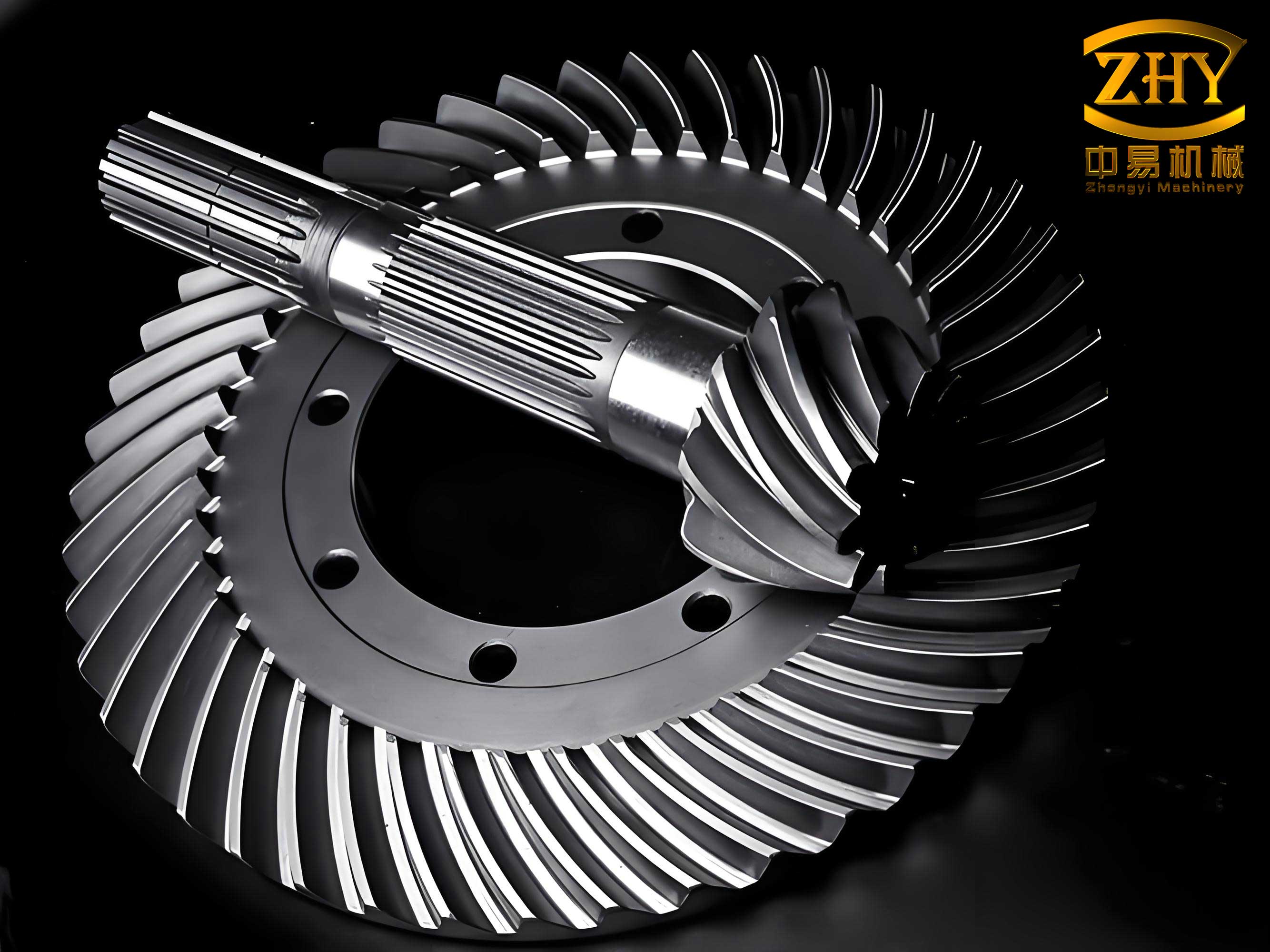
Before diving into scraping, it is essential to understand the broader context of finishing methods for hardened spiral bevel gears. Generally, three primary techniques are employed: lapping, grinding, and scraping. Each method has its own merits and drawbacks, which I will summarize in a comparative table. Lapping is a traditional process that involves rubbing abrasive compounds between mating gear teeth to improve surface finish and adjust contact patterns. It is relatively simple and low-cost but is ineffective in correcting major geometric errors or heat treatment distortions. Moreover, lapping cannot eliminate pitch errors and may only provide marginal improvements in noise reduction. Grinding, on the other hand, uses abrasive wheels to remove material from the tooth surfaces, offering high precision and excellent surface quality. However, grinding spiral bevel gears is often slow, expensive, and prone to thermal damage like burns and oxidation due to high grinding forces and temperatures. This can compromise the gear’s fatigue life and overall performance. In contrast, scraping utilizes cutting tools with negative rake angles and hard materials like carbide or cubic boron nitride (CBN) to machine hardened surfaces directly. It combines the efficiency of cutting with the precision of finishing, making it suitable for post-heat-treatment correction. The following table provides a detailed comparison of these methods, highlighting key parameters such as material removal rate, surface roughness, and typical applications for spiral bevel gears.
| Finishing Method | Material Removal Rate | Surface Roughness (Ra) | Typical Gear Hardness (HRC) | Advantages | Disadvantages |
|---|---|---|---|---|---|
| Lapping | Low (0.01–0.05 mm/min) | 0.4–1.6 μm | 55–62 | Simple, low cost, improves contact pattern | Cannot correct major errors, limited to minor adjustments |
| Grinding | Medium (0.1–0.3 mm/min) | 0.1–0.4 μm | 57–65 | High precision, excellent surface finish | Slow, expensive, risk of thermal damage |
| Scraping | High (0.3–0.8 mm/min) | 0.25–0.5 μm | 57–63 | High efficiency, good surface integrity, cost-effective | Requires robust machinery, tool wear management |
The scraping process for spiral bevel gears involves using a cutter head with multiple inserts, similar to those used in gear milling but designed for hardened materials. The cutter engages the gear teeth in a generating motion, removing a thin layer of material to correct distortions and achieve the desired tooth geometry. One of the key advantages of scraping is its high material removal rate, which can be up to three times that of grinding, as indicated in the table. This is due to the cutting action rather than abrasive wear, allowing for faster production cycles. Additionally, scraping generates less heat compared to grinding; typically, only about one-fifth of the thermal energy is produced, with most heat carried away by chips. This minimizes the risk of surface burns and preserves the metallurgical integrity of the gear tooth surface. Furthermore, the plastic deformation induced during scraping can enhance surface hardness through work hardening, as the microstructure is refined and dislocation density increases. This phenomenon can be described by the Hall-Petch relationship, which relates grain size to yield strength: $$\sigma_y = \sigma_0 + \frac{k}{\sqrt{d}}$$ where $\sigma_y$ is the yield strength, $\sigma_0$ is a material constant, $k$ is the strengthening coefficient, and $d$ is the average grain diameter. In scraping, the intense shear forces reduce the effective grain size at the surface, leading to improved hardness and wear resistance for spiral bevel gears.
When implementing scraping for spiral bevel gears, several critical factors must be considered to ensure success and avoid common pitfalls such as tool chipping or poor surface quality. First, machine tool selection is paramount. The machine must have high rigidity and damping characteristics to withstand the intermittent cutting forces and vibrations inherent in scraping hardened surfaces. For spiral bevel gears, conventional gear milling machines like the Gleason series or similar models (e.g., GH35) can be adapted for scraping, provided they are in good condition and properly maintained. Second, the workpiece material and its heat treatment play a crucial role. Common materials for spiral bevel gears include alloy steels like 20CrMnTi and 17CrNiMo6, which are often carburized and quenched. To ensure uniform microstructure and minimize distortion, forging and normalizing are recommended before rough machining. After heat treatment, gear teeth edges may become brittle and uneven, so chamfering is essential prior to scraping to prevent tool damage. Third, tool geometry and material are vital. Hard alloy inserts with negative rake angles (e.g., -15°) and negative inclination angles (e.g., -12°) are typically used to enhance edge strength and resist impact loads. Advanced materials like CBN-tipped inserts offer even better performance but at higher cost. The tool design also influences accuracy; for instance, the “oblique line profiling method” and “oblique arc profiling method” have been proposed to optimize cutter shape for spiral bevel gears, reducing profile errors and improving tool life. Fourth, process parameters such as cutting speed, feed rate, and depth of cut must be carefully selected. Based on empirical studies, the cutting speed $v_c$ for scraping hardened spiral bevel gears can be calculated using the formula: $$v_c = \frac{\pi \cdot D \cdot n}{1000}$$ where $D$ is the cutter diameter in mm, and $n$ is the spindle speed in rpm. For typical spiral bevel gears with hardness around HRC 60, $v_c$ ranges from 50 to 80 m/min. The feed rate $f$ is usually set between 0.05 and 0.1 mm per tooth, depending on gear module and tool condition. The scraping allowance, which is the amount of material left after heat treatment for finishing, should be controlled precisely. A general guideline is to allocate 0.15–0.2 mm for gears with module less than 5 mm, 0.2–0.28 mm for module 5–10 mm, and 0.25–0.35 mm for larger modules. This allowance compensates for distortion while minimizing cutting forces. Lastly, alignment and setup are critical. The gear must be mounted using the same datums as in pre-heat-treatment machining to ensure consistency. Tool positioning and engagement should be verified through trial cuts to avoid errors in tooth profile and lead.
The development of scraping technology for spiral bevel gears has evolved over decades, with significant contributions from various countries. In the 1960s, Japan and the Soviet Union began exploring hard gear cutting techniques. Japanese researchers, led by Professor Masato Aiura, conducted extensive experiments on tool materials, cutting parameters, and applications for hard skiving. Companies like Sumitomo Electric developed cutter heads with CBN-tipped inserts that could be mounted on standard gear cutting machines, enabling the machining of large spiral bevel gears with modules up to 21.75 mm and hardness up to HRC 63. In the United States, Gleason Company introduced formal documentation on hard finishing in 1981, advocating the use of negative rake angle carbide inserts on machines like the No. 641 and No. 655 for spiral bevel gears. These advancements demonstrated that scraping could achieve surface roughness as low as Ra 0.25–0.5 μm and gear accuracy equivalent to AGMA class 6–7. In China, research on scraping started in the 1980s, with successful trials on straight bevel gears in coal mining equipment. Through simulation and experimentation, optimal tool geometries and cutting conditions were identified, leading to the adoption of scraping for spiral bevel gears in industries such as automotive and wind power. Today, scraping is recognized as a reliable method for correcting heat treatment distortions in spiral bevel gears, offering a balance between precision, efficiency, and cost. The historical progression underscores the continuous improvement in tool materials, machine capabilities, and process understanding, which I will further elaborate in the context of recent innovations.
To illustrate the practical application of scraping for spiral bevel gears, let me present a detailed case study based on typical industrial parameters. Consider a pair of spiral bevel gears with an axis angle of 90°, module of 6 mm, pressure angle of 20°, and spiral angle of 35°. The gear pair consists of a pinion with 12 teeth and a gear with 35 teeth, both with a face width of 30 mm. The gear parameters are summarized in the table below, which includes key dimensions and design specifications essential for scraping setup.
| Parameter | Pinion (Small Gear) | Gear (Large Gear) |
|---|---|---|
| Number of Teeth | 12 | 35 |
| Module (mm) | 6 | |
| Pressure Angle (°) | 20 | |
| Spiral Angle (°) | 35 | |
| Face Width (mm) | 30 | |
| Axis Angle (°) | 90 | |
| Addendum Modification Coefficient | 0.344 | -0.344 |
| Tangential Modification Coefficient | 0.075 | -0.075 |
| Whole Depth (mm) | 11.328 | |
| Addendum (mm) | 7.14 | 3.06 |
| Dedendum (mm) | 4.188 | 8.268 |
| Pitch Cone Angle (°) | 18.92464 | 71.07536 |
For scraping, the cutter head parameters are equally important. In this case, a 152.4 mm diameter cutter head with a blade number of 14.66 is used for the gear, while a 152.6 mm diameter cutter head with a blade number of 7.43 is used for the pinion. The offset distance (e.g., 3.074881 mm for the gear) is set based on the gear geometry to ensure proper tooth generation. The manufacturing process begins with gear blank forging and rough machining, followed by normalizing to homogenize the microstructure. Then, pre-heat-treatment gear cutting is performed to near-net shape, leaving a scraping allowance of 0.25 mm per flank, as the module is 6 mm (within the 5–10 mm range). After carburizing and quenching to achieve a surface hardness of HRC 58–60 and a case depth of about 1 mm, the gear undergoes chamfering to remove sharp edges. The scraped surfaces, such as the bore and mounting faces, are ground to ensure accurate locating during scraping. The scraping operation is carried out on a GH35 milling machine, which offers sufficient rigidity. The tool inserts are made of hard alloy (e.g., YT15 or similar) with a -15° rake angle and -12° inclination angle. The cutting speed is set to 50 m/min, calculated using the formula above with a cutter diameter of 152.4 mm and spindle speed adjusted accordingly. The feed rate is 0.08 mm/min, and the depth of cut is gradually increased in steps of 0.05 mm until the full allowance is removed. During setup, the gear is aligned using the same datums as in pre-heat-treatment machining, and tool engagement is verified through test cuts. After scraping, the gear pair is inspected for tooth profile, pitch accuracy, and surface roughness. Contact pattern tests are conducted on a rolling tester to ensure proper meshing. Typically, scraping achieves a surface roughness of Ra 0.3–0.5 μm, contact pattern coverage of 60–65% in height and 80–90% in length, and noise reduction of 3–5 dB compared to un-finished gears. This case demonstrates the effectiveness of scraping for spiral bevel gears in real-world applications.
Looking ahead, the future of scraping technology for spiral bevel gears is promising, with several avenues for improvement and innovation. First, tool material optimization is a key area. While hard alloys and CBN are currently dominant, emerging materials like advanced ceramics or diamond-coated inserts could further enhance tool life and cutting performance. Research into multi-layer coatings with high thermal stability may reduce wear and enable higher cutting speeds for spiral bevel gears. Second, cutter design methodologies can be refined using computational tools. The “oblique arc profiling method” has already reduced errors compared to earlier approaches, but finite element analysis (FEA) and computer-aided design (CAD) can lead to more sophisticated profiles that minimize stress concentrations and improve chip flow. For instance, the cutter profile can be optimized using parametric equations that account for tooth geometry and cutting dynamics. A general form for the cutter edge curve in spiral bevel gear scraping can be expressed as: $$x(u) = R \cdot \cos(u), \quad y(u) = R \cdot \sin(u), \quad z(u) = f(u)$$ where $R$ is the cutter radius, $u$ is a parameter, and $f(u)$ defines the profile variation. Third, the integration of scraping with numerical control (NC) and computer numerical control (CNC) systems will revolutionize the process. Modern CNC gear cutting machines offer high precision and flexibility, allowing for adaptive control of scraping parameters based on real-time feedback. This can compensate for tool wear and variations in gear hardness, ensuring consistent quality for spiral bevel gears. Additionally, the use of simulation software for virtual scraping trials can reduce setup time and material waste. Fourth, environmental and economic considerations will drive the adoption of scraping. Since scraping consumes less energy and produces fewer hazardous wastes (e.g., grinding sludge) compared to grinding, it aligns with sustainable manufacturing trends. Moreover, the higher efficiency translates to lower production costs, making it attractive for mass production of spiral bevel gears in industries like automotive and renewable energy. Finally, interdisciplinary research combining tribology, metallurgy, and mechanics will deepen our understanding of the scraping process. For example, studies on the residual stress distribution after scraping can inform heat treatment adjustments to improve gear fatigue life. In summary, the ongoing advancements in tool technology, machine intelligence, and process modeling will elevate scraping from a niche technique to a mainstream solution for high-precision spiral bevel gear finishing.
In conclusion, the scraping technology for hardened spiral bevel gears represents a significant advancement in gear manufacturing, addressing the challenges posed by heat treatment distortions while offering superior efficiency and surface integrity. Through this comprehensive review, I have explored the fundamental principles, comparative advantages, key implementation factors, historical development, practical applications, and future prospects of scraping. The comparison with lapping and grinding highlights scraping’s unique benefits, such as high material removal rates, reduced thermal damage, and enhanced surface hardness. The case study illustrates how scraping parameters can be tailored for specific spiral bevel gear designs, resulting in improved accuracy and performance. Looking forward, innovations in tool materials, cutter design, and CNC integration will further enhance the capabilities of scraping, making it an increasingly viable alternative to traditional methods. As industries continue to demand higher-quality and more durable spiral bevel gears, the adoption of scraping is likely to grow, supported by ongoing research and technological improvements. By understanding and optimizing this process, manufacturers can achieve better gear performance, lower production costs, and contribute to the advancement of mechanical transmission systems. I hope this article provides valuable insights for engineers and researchers working on spiral bevel gears, encouraging further exploration and application of scraping technology in their endeavors.