
The continuous advancement of the manufacturing industry places ever-increasing demands on gear processing, especially in the realm of finishing. Among various finishing technologies, internal gear power honing stands out as a high-precision and highly efficient method. This process not only effectively corrects errors introduced by preceding machining operations but also significantly improves the surface topography of the workpiece. At its core, the process involves the conjugated meshing between an internal gear honing wheel and the external gear workpiece, akin to the interaction of a pair of crossed helical gears. The honing wheel, a specialized abrasive tool, removes material via the relative sliding of its abrasive grains against the workpiece surface under controlled contact conditions.
Like conventional grinding wheels, the internal gear honing wheel suffers from gradual dulling, abrasive wear, and loading after sustained honing cycles. This degradation leads to a decline in its cutting capability, ultimately resulting in deteriorating workpiece quality. To restore its performance, the honing wheel must be periodically dressed. The dressing tool is typically a precision gear-shaped diamond roller. In a standard dressing operation, the diamond roller is mounted in the workpiece spindle position, and the honing wheel is fed radially towards it, simulating a “machining” pass without altering other kinematic parameters. This dressing process essentially constitutes a secondary envelope of an involute surface: the first envelope forms the honing wheel tooth surface from the diamond roller’s involute surface, and the subsequent honing process uses this honing wheel surface to generate (envelope) the workpiece tooth surface.
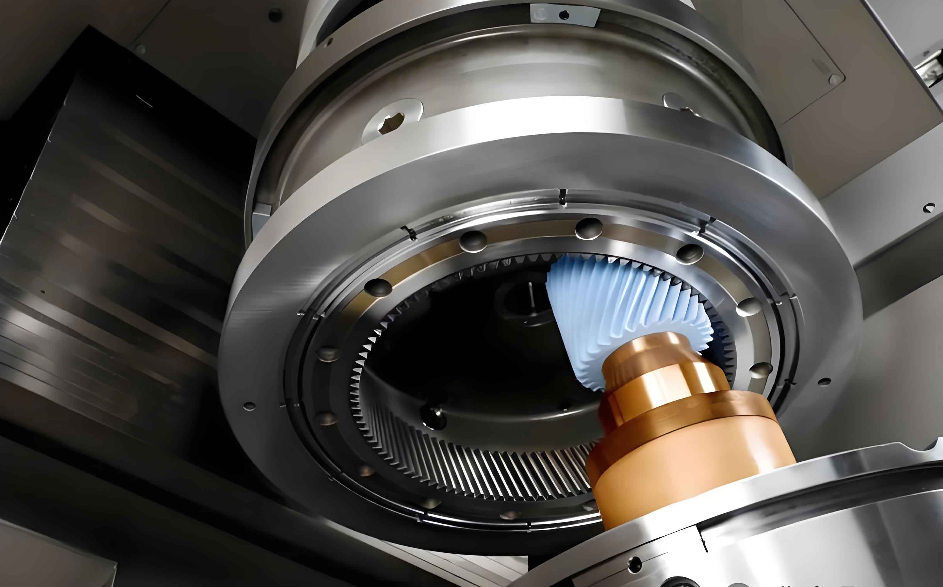
However, practical experience reveals a critical issue with the standard radial dressing method. While theory suggests that a workpiece machined with a dressed honing wheel should perfectly replicate the diamond roller’s profile (given identical parameters), the reality is a progressive, often unacceptable, change in the workpiece tooth form after consecutive dressing cycles. This instability compromises part quality consistency and leads to premature honing wheel retirement, reducing its usable life. This article investigates the root cause of this problem and presents a modified dressing strategy—the variable crossed-axis angle method—to stabilize the gear honing process and ensure consistent workpiece geometry.
Mathematical Foundation of Conjugated Contact in Gear Honing
The fundamental principle governing the gear honing operation is the conjugated contact between the honing wheel tooth surface and the workpiece tooth surface. To analyze the contact conditions, a precise mathematical model of this meshing relationship is essential.
Spatial Coordinate Systems
Four coordinate systems are established to describe the relative motion and geometry, as illustrated in the analysis. These include fixed coordinate systems \( S(O-xyz) \) for the workpiece and \( S_p(O_p-x_py_pz_p) \) for the honing wheel, as well as moving coordinate systems \( S_1(O_1-x_1y_1z_1) \) attached to the workpiece and \( S_2(O_2-x_2y_2z_2) \) attached to the honing wheel. The key spatial relationship parameters are the center distance \( a \) (distance between origins \( O \) and \( O_p \)) and the crossed-axis angle \( \Sigma \) (angle between the \( z \)-axis and \( z_p \)-axis). The rotational speeds and angles are \( \omega_1, \varphi_1 \) for the workpiece and \( \omega_2, \varphi_2 \) for the honing wheel.
Workpiece Tooth Surface Equation
The workpiece surface is a standard involute helicoid. In its attached coordinate system \( S_1 \), a point \( M \) on this surface can be expressed using parameters based on the base circle radius \( r_b \), the spiral angle \( \beta_1 \), and specific angular parameters defining its position on the involute curve and along the tooth width. The coordinates are given by:
$$ x_1 = r_b \cos(\sigma_0 + \theta + \lambda) + r_b \lambda \sin(\sigma_0 + \theta + \lambda) $$
$$ y_1 = r_b \sin(\sigma_0 + \theta + \lambda) – r_b \lambda \cos(\sigma_0 + \theta + \lambda) $$
$$ z_1 = p \theta $$
where \( p = r_1 / \tan \beta_1 \) is the lead, \( r_1 \) is the pitch radius, \( \sigma_0 \) is the involute start angle, \( \theta \) is the helix increment angle, and \( \lambda \) is the involute roll angle.
The Conjugated Meshing Equation
The condition for conjugated contact at any point is that the relative velocity vector \( \mathbf{v} \) is orthogonal to the common surface normal vector \( \mathbf{n} \) at that point:
$$ \mathbf{v} \cdot \mathbf{n} = 0 $$
By transforming the surface point from \( S_1 \) to the fixed frame \( S \) and deriving expressions for \( \mathbf{v} \) and \( \mathbf{n} \), the meshing equation can be formulated. For a given set of honing wheel and workpiece parameters, this equation establishes a functional relationship \( f(\varphi_1, \theta, \lambda) = 0 \). For any instant defined by the workpiece rotation angle \( \varphi_1 \), this equation, combined with the surface equations, defines the instantaneous line of contact on the tooth surface. The totality of these contact lines over a full mesh cycle generates the workpiece tooth flank via envelope theory.
Problem Analysis: Tooth Contact Variation Induced by Single Radial Dressing
The variation in the final workpiece tooth profile originates from a change in the contact state between the honing wheel and workpiece surfaces after dressing. Using the mathematical model, the instantaneous contact lines for the initial state (dressing amount \( \Delta a = 0 \)) and after a significant radial dressing (e.g., \( \Delta a = 2 \, \text{mm} \)) can be simulated.
The following table lists the key parameters for a typical transmission gear and its corresponding internal gear honing wheel used in the analysis:
| Component | Parameter | Value |
|---|---|---|
| Common | Normal Module \( m_n \) (mm) | 2.25 |
| Normal Pressure Angle \( \alpha_n \) (deg) | 17.5 | |
| Workpiece Gear | Number of Teeth \( z_1 \) | 73 |
| Helix Angle \( \beta_1 \) (deg) | 33 | |
| Face Width \( b_1 \) (mm) | 27 | |
| Honing Wheel | Number of Teeth \( z_2 \) | 123 |
| Helix Angle \( \beta_2 \) (deg) | 41.722 | |
| Face Width \( b_2 \) (mm) | 30 |
Simulation results clearly show a substantial shift in the position of the contact lines after a 2 mm radial dressing infeed. Conceptually, the intersection point of the contact lines from the two flanks of a honing wheel tooth, projected onto the tooth profile, can be considered an “equivalent force application point.” After radial dressing, this point moves from a location near the honing wheel tooth tip towards the root.
Since the internal gear honing wheel is a compliant tool with an elastic body, it is the more deformable element in the contact pair. The shift of the equivalent force application point alters the local contact pressure distribution. Specifically, the pressure exerted by the honing wheel tip on the workpiece root becomes insufficient, while the contact pressure in other regions changes accordingly. This altered pressure distribution directly results in a different material removal pattern during gear honing, manifesting as a gradual change in the generated workpiece tooth profile. Each radial dressing cycle introduces a minor change that accumulates, eventually driving the workpiece profile out of tolerance and rendering the honing wheel unusable long before its abrasive potential is exhausted.
The Variable Crossed-Axis Angle Dressing Methodology
To counteract the detrimental effects of simple radial dressing, a modified strategy is proposed: the Variable Crossed-Axis Angle Dressing Method. The core idea is to maintain a stable contact condition at a specific, predetermined point on the workpiece tooth surface by introducing a compensating adjustment to the crossed-axis angle \( \Sigma \) during dressing, in conjunction with the radial infeed \( \Delta a \). Stabilizing the contact at this representative point approximates the stabilization of the overall contact pattern.
Definition of the Fixed Reference Point C
A specific point \( C \) on the workpiece tooth flank is chosen as the reference. This point is defined in the workpiece coordinate system \( S_1 \) as the intersection of the “0° contact line” (the contact line at workpiece rotation angle \( \varphi_1 = 0°) and the transverse plane (\( \theta = 0 \)) involute curve. Therefore, for point \( C \), we have \( \varphi_{1C} = 0° \) and \( \theta_C = 0° \). Substituting these values and the basic gear parameters into the meshing equation allows for the calculation of its corresponding involute roll angle \( \lambda_C \). For the parameters in Table 1, \( \lambda_C = 20.420° \).
Establishing the Relationship Between Dressing Infeed and Axis Angle
In the initial state (\( \Delta a = 0 \)), point \( C \) naturally satisfies the meshing equation \( f(\varphi_{1C}, \theta_C, \lambda_C) = 0 \). After a radial dressing infeed \( \Delta a \), the center distance changes to \( a’ = a + \Delta a \). If no other parameter is adjusted, the meshing condition at point \( C \) is violated. To enforce the meshing condition at \( C \) precisely, a modified crossed-axis angle \( \Sigma’ \) is introduced. The meshing equation is thus rewritten for point \( C \):
$$ (\theta_C p^2 – \lambda_C r_b^2) \sin\Sigma’ \sin(\tau_C + \varphi_{1C}) + (a’ p \cos\Sigma’ – r_b^2 \sin\Sigma’) \cos(\tau_C + \varphi_{1C}) = r_b a’ \sin\Sigma’ – (\cos\Sigma’ – i_{12}) p r_b $$
where \( \tau_C = \sigma_0 + \theta_C + \lambda_C \) and \( i_{12} \) is the gear ratio. With all parameters for point \( C \) known, this equation defines a functional relationship \( f'(a’, \Sigma’) = 0 \).
This relationship implies that for any new center distance \( a’ \) resulting from a cumulative dressing infeed \( \Delta a \), there exists a specific crossed-axis angle \( \Sigma’ \) that ensures the conjugated meshing condition is exactly satisfied at the fixed point \( C \). By dressing the honing wheel with this paired set of parameters \( (a’, \Sigma’) \), the contact condition at \( C \) is preserved. The calculated adjustment is relatively small but crucial. The following table shows the required axis angle for different dressing amounts:
| Cumulative Dressing \( \Delta a \) (mm) | Center Distance \( a’ \) (mm) | Crossed-Axis Angle \( \Sigma’ \) (deg) |
|---|---|---|
| 0 | 87.471 | 8.722 |
| 1 | 88.471 | 9.064 |
| 2 | 89.471 | 9.402 |
| 3 | 90.471 | 9.734 |
Comparative Analysis of Contact Lines
Simulating the contact lines for different dressing amounts using the corresponding \( (a’, \Sigma’) \) pairs from the variable axis angle method reveals a significant improvement. Compared to the substantial shift observed with single radial dressing, the contact lines for different \( \Delta a \) values now nearly coincide. While minor deviations exist upon close inspection, the overall contact pattern across the tooth flank remains remarkably stable. This theoretical result strongly suggests that the variable crossed-axis angle method can effectively mitigate the root cause of workpiece profile variation in the gear honing process.
Experimental Verification in Gear Honing
To validate the practical effectiveness of the proposed variable axis angle dressing method, a series of gear honing tests were conducted.
Experimental Setup and Procedure
The tests were performed on an HMX-400 Fassler CNC internal gear power honing machine. Workpiece quality was measured using a Klingelnberg P40 gear measuring center. The workpiece and honing wheel parameters matched those in Table 1. The experimental procedure was designed as follows:
- Initial gear honing commenced with a crossed-axis angle slightly below 9°. After every 20 workpieces honed, the honing wheel was dressed. Each dressing operation used an infeed of \( \Delta a = 0.1 \, \text{mm} \), and the corresponding axis angle correction \( \Delta\Sigma \) was calculated and applied based on the derived relationship \( f'(a’, \Sigma’) = 0 \).
- When the machine’s axis angle display, having accumulated these corrections, reached approximately 9°, three workpieces honed at this specific angle were randomly selected for inspection on the gear measuring center. Their tooth profile error reports were saved.
- This sampling process was repeated each time the axis angle accumulated an additional 0.5°. This resulted in nine sample groups (A1 through A9), with group A9 corresponding to an axis angle near 13°.
- The tooth profile results from all groups were analyzed and compared to assess the consistency of the workpiece geometry produced under the variable axis angle dressing regimen.
Results and Discussion
Analysis of the measured tooth profile traces from the different sample groups confirmed the efficacy of the method. The characteristic shape and form of the workpiece tooth profile remained consistent across the entire range of axis angles (from ~9° to ~13°). No progressive, systematic change in the profile shape was observed. Furthermore, the surface quality of the honed workpieces was maintained or even improved as the honing wheel was periodically dressed, indicating effective restoration of the wheel’s cutting ability. The experimental outcomes thus align with the theoretical predictions, demonstrating that the variable crossed-axis angle dressing method successfully stabilizes the gear honing process, ensures consistent workpiece accuracy over extended honing wheel life, and enables full utilization of the honing wheel’s abrasive potential.
Conclusion
The internal gear power honing process is a critical finishing technology for high-quality gears. However, the standard practice of dressing the honing wheel using a single radial infeed leads to an unstable contact condition between the wheel and workpiece, causing a gradual, undesirable change in the generated workpiece tooth profile. This study identified the root cause by analyzing the mathematical model of conjugated contact, showing that radial dressing shifts the instantaneous contact lines and the equivalent force application point on the honing wheel tooth.
To solve this problem, a variable crossed-axis angle dressing method was developed. This method introduces a compensating adjustment to the crossed-axis angle for each radial dressing infeed, calculated to maintain the conjugated meshing condition at a fixed reference point on the workpiece tooth flank. Theoretical contact line modeling confirmed that this approach significantly improves the stability of the contact pattern compared to the single radial method.
Practical gear honing tests conducted on a CNC honing machine validated the method’s effectiveness. Workpieces honed across a wide range of axis angles, adjusted according to the proposed strategy, exhibited consistent tooth profile geometry without trend-like deviations. This method enhances the stability and predictability of the gear honing process, improves part quality consistency, and extends the usable life of the internal gear honing wheel, contributing to higher overall process efficiency and cost-effectiveness in precision gear manufacturing.