
In the realm of mechanical power transmission, spiral gears, particularly involute spiral gears, have garnered significant attention due to their superior performance characteristics, such as smooth operation, high load capacity, and reduced noise. As a researcher focused on advanced manufacturing techniques, I have dedicated substantial effort to exploring precision grinding methods for these gears. Form grinding, a high-precision finishing process, stands out for its ability to efficiently produce hard-faced spiral gears with exceptional accuracy. The core challenge lies in dressing the grinding wheel to accurately replicate the complex profile of the involute spiral gear tooth flank. This article delves into the mathematical modeling of the involute helicoid, the computational methods for determining the grinding wheel’s axial section, and the practical implementation of CNC-based wheel dressing. Through this first-person account, I aim to elucidate the intricacies involved in achieving high-quality spiral gear production via form grinding.
The foundation of precise form grinding for spiral gears rests on a thorough understanding of the gear tooth geometry. The involute spiral surface is a helicoid generated by a straight line performing a screw motion. To model this, consider a fixed coordinate system (O – x, y, z). A straight generatrix, initially tangent to a base cylinder of radius \(r_b\), undergoes a helical motion with a constant lead parameter \(p\). The resulting surface is the involute helicoid. The parametric equations for a right-handed involute helicoid can be derived as follows. Let the generatrix be defined in its initial position, where a point on it is parameterized by \(u\), the distance from the point of tangency. The coordinates are:
$$ x_0 = r_b, \quad y_0 = u \cos \alpha, \quad z_0 = u \sin \alpha $$
Here, \(\alpha\) is the base helix angle, related to the base radius and the helical parameter by \(\alpha = \arctan(p / r_b)\). After a rotation by angle \(\theta\) and a translation \(p\theta\) along the z-axis, the helicoid equations become:
$$ x = r_b \cos \theta – u \cos \alpha \sin \theta $$
$$ y = r_b \sin \theta + u \cos \alpha \cos \theta $$
$$ z = u \sin \alpha + p \theta $$
These equations fully describe the involute spiral gear tooth surface. The normal vector at any point on this surface is crucial for subsequent contact analysis. By differentiating with respect to the parameters, the normal vector components \((n_x, n_y, n_z)\) are obtained:
$$ n_x = u \cos \alpha \sin \alpha \sin \theta $$
$$ n_y = -u \cos \alpha \sin \alpha \cos \theta $$
$$ n_z = u \cos^2 \alpha $$
The end section of the helicoid (z=0) yields the familiar involute curve in the transverse plane, given by:
$$ x = r_b \cos \theta + r_b \theta \sin \theta $$
$$ y = r_b \sin \theta – r_b \theta \cos \theta $$
This mathematical description forms the bedrock for analyzing the interaction between the grinding wheel and the spiral gear workpiece.
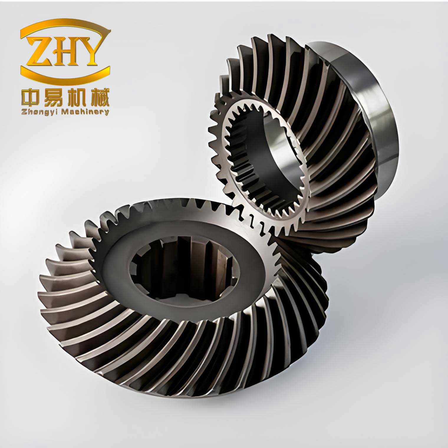
In form grinding, a revolving grinding wheel, shaped to the exact negative profile of the gear tooth space, is used. The wheel’s surface and the gear’s spiral surface must maintain continuous contact along a spatial curve during the relative motion. To establish the condition for this contact, we define two coordinate systems: the workpiece system (O – x, y, z) attached to the spiral gear and the wheel system (O’ – X, Y, Z) attached to the grinding wheel. The transformation between these systems involves the center distance \(a\) and the shaft angle \(\Sigma\). For grinding a spiral gear with helix angle \(\beta\), the shaft angle is typically \(\Sigma = 90^\circ – \beta\). The coordinate transformation is:
$$ X = a – x $$
$$ Y = -y \cos \Sigma – z \sin \Sigma $$
$$ Z = -y \sin \Sigma + z \cos \Sigma $$
The contact condition, derived from the requirement that the relative velocity lies in the common tangent plane, leads to the equation:
$$ z n_x + a n_y \cot \Sigma + (a – x + p \cot \Sigma) n_z = 0 $$
Substituting the expressions for \(x, y, z, n_x, n_y, n_z\) from the helicoid equations yields a relationship between the parameters \(u\) and \(\theta\) that defines the contact line:
$$ (u + p \theta \sin \alpha) \sin \theta – (a \sin \alpha + r_b \cos \alpha) \cos \theta + (p \cot \Sigma + a) \cos \alpha = 0 $$
This equation, coupled with the helicoid parametric equations, allows us to compute points on the contact line for given parameter values.
The axial profile of the grinding wheel is the cross-section in the X-Z plane of the wheel coordinate system. By mapping the contact line points into the wheel system using the transformation and then considering the wheel as a surface of revolution around its Z-axis, the radial distance \(R\) from the wheel axis for each Z-coordinate is given by:
$$ R = \sqrt{X^2 + Y^2} $$
Thus, the set of points \((R, Z)\) defines the required axial section of the form grinding wheel for the involute spiral gear. The complexity of these equations, involving trigonometric and transcendental terms, necessitates numerical methods for solution.
To illustrate the computational process, I developed a MATLAB program that solves the contact condition and generates the wheel profile. The key steps involve:
- Defining gear parameters: normal module \(m_n\), number of teeth \(Z\), helix angle \(\beta\), normal pressure angle \(\alpha_n\).
- Calculating derived parameters: base radius \(r_b\), helical parameter \(p = \frac{m_n Z}{2 \sin \beta}\), shaft angle \(\Sigma\).
- Selecting a range for the parameter \(\theta\).
- For each \(\theta\), solving the nonlinear contact equation for \(u\) using MATLAB’s
fsolvefunction. - Computing the corresponding workpiece coordinates \((x, y, z)\) and transforming them to wheel coordinates \((X, Y, Z)\).
- Calculating \(R\) and \(Z\) to obtain the axial section points.
For a spiral gear with \(m_n = 12 \, \text{mm}\), \(Z = 15\), \(\beta = 30^\circ\), \(\alpha_n = 20^\circ\), and a wheel diameter of 300 mm, the program efficiently computes the profile. The end section of the spiral gear, plotted using MATLAB, clearly shows the involute shape. The calculated wheel axial section for the right-hand flank and the complete tooth space (both flanks) are depicted graphically. The accuracy of this numerical approach is vital for dressing the wheel precisely.
The following table summarizes the key parameters and their symbols used in the mathematical model for spiral gears:
| Symbol | Description | Typical Unit |
|---|---|---|
| \(r_b\) | Base radius of the spiral gear | mm |
| \(\beta\) | Helix angle at reference circle | degrees |
| \(\alpha\) | Base helix angle | degrees |
| \(p\) | Helical parameter (lead/2π) | mm |
| \(m_n\) | Normal module | mm |
| \(\alpha_n\) | Normal pressure angle | degrees |
| \(a\) | Center distance between wheel and gear axes | mm |
| \(\Sigma\) | Shaft angle between wheel and gear axes | degrees |
| \(u, \theta\) | Parameters defining the helicoid | dimensionless |
With the wheel profile data computed, the next critical step is physically dressing the grinding wheel. Traditional dressing methods often fall short for complex spiral gear profiles. Modern CNC grinding machines equipped with dedicated wheel dressers offer a superior solution. In my research, I utilized a CNC grinding machine with a two-axis dresser. The dresser features two diamond nibs, one for the left flank and one for the right flank of the wheel profile. The dressing process is automated and follows a precise path controlled by CNC programs derived from the calculated \((R, Z)\) data.
The dressing sequence is systematic. The left diamond nib starts from a home position, moves to approach the wheel, then traces the contour corresponding to the left flank of the wheel’s axial section (from one end to the other), retracts, and returns home. Subsequently, the right diamond nib performs a similar motion for the right flank. This two-nib approach minimizes wear and ensures high profile accuracy. The CNC system allows for easy compensation of wheel wear by recalculating the dressing path based on the current wheel diameter, maintaining consistent gear tooth geometry throughout the grinding process. The ability to dress complex contours reliably is a hallmark of advanced spiral gear manufacturing.
The practical implementation was conducted on a precision thread grinding machine retrofitted with a CNC wheel dresser. After dressing the wheel according to the computed profile, form grinding trials were performed on spiral gear blanks. The ground spiral gears were inspected using a gear measurement center. The results demonstrated significant improvements. The profile deviation of the involute spiral gear teeth was minimized, with errors consistently within ±10 μm. This level of precision is crucial for high-performance spiral gear applications in industries such as aerospace, automotive, and robotics. The surface finish achieved was also superior, reducing the need for post-grinding operations.
To further elucidate the advantages of form grinding for spiral gears, consider the following comparative analysis summarized in the table below:
| Aspect | Traditional Gear Hobbing | Form Grinding with CNC Dressing |
|---|---|---|
| Accuracy | Moderate, limited by tool wear and machine dynamics | High, dictated by precisely dressed wheel profile |
| Surface Finish | Good, but may require finishing | Excellent, often as-ground finish is sufficient |
| Applicability to Hard Materials | Limited, typically for soft gears | Ideal for hardened spiral gears |
| Flexibility for Complex Profiles | Lower, tooling changes needed for different gears | High, wheel dressing program can be adapted easily |
| Production Efficiency for Batch | High for large batches | Very high for precision batches, minimal setup time |
The mathematical framework also allows for optimization. For instance, the center distance \(a\) and the wheel diameter can be optimized to minimize undercutting or to improve the wheel’s structural integrity during grinding. Additionally, the shaft angle \(\Sigma\) is critical; slight deviations can lead to profile errors. The contact condition equation can be extended to account for such variations, enabling error analysis and compensation. In my work, I explored the sensitivity of the wheel profile to changes in helix angle \(\beta\). A small change \(\Delta \beta\) alters \(\Sigma\) and \(p\), which in turn affects the contact line. Re-solving the equations with updated parameters shows how the wheel profile must be adjusted. This is vital for manufacturing spiral gears with tight tolerance requirements.
Another important consideration is the grinding process parameters, such as wheel speed, feed rate, and depth of cut. While the focus here is on wheel dressing, these parameters interact with the wheel profile to affect the final gear quality. For spiral gears, the grinding process must also manage the continuous engagement along the helical path. The CNC machine coordinates the rotary motion of the gear (C-axis) with the linear feed (X-axis) to generate the helix. The dressed wheel profile ensures that each point along the tooth flank is correctly generated. This synchronization is key to avoiding deviations in lead and profile.
The role of software in this ecosystem cannot be overstated. Beyond MATLAB for profile computation, CAM software is used to generate the CNC code for both the dressing cycle and the grinding cycle. The integration of mathematical models into CAM systems allows for a seamless digital thread from design to finished spiral gear. I developed scripts that automate the conversion of wheel profile data into G-code for the dresser, significantly reducing manual programming effort and potential errors.
In conclusion, the precision form grinding of involute spiral gears is a sophisticated process that hinges on accurate mathematical modeling and advanced wheel dressing technology. Through the derivation of the involute helicoid equations, the establishment of the wheel-workpiece contact condition, and the numerical computation of the grinding wheel’s axial section, we can achieve a deep understanding of the geometric interactions. The implementation of CNC-based dressing using diamond nibs enables the practical realization of complex wheel profiles, leading to spiral gears with exceptional dimensional accuracy and surface quality. This methodology not only enhances the performance of spiral gears but also boosts manufacturing efficiency by reducing setup times and enabling the processing of hardened materials. As demand for high-precision spiral gears grows in various advanced mechanical systems, the techniques described here will continue to be refined and adopted, pushing the boundaries of gear manufacturing technology.
Future work may involve extending the model to non-involute spiral gear profiles, such as cycloidal or double-circular-arc spirals, which are used in specialized applications. Additionally, real-time monitoring and adaptive dressing strategies could be integrated to compensate for wheel wear dynamically during the grinding of spiral gears. The integration of machine learning algorithms to predict optimal dressing intervals based on grinding forces and surface finish measurements is another promising avenue. The journey toward perfecting spiral gear manufacturing is ongoing, and with each advancement, we move closer to realizing transmissions that are quieter, more efficient, and more reliable.