
In the field of precision transmission systems, the rotary vector reducer plays a crucial role due to its high torque capacity, compact size, and low backlash. As a key component in robotics and industrial automation, the performance of rotary vector reducers hinges on the design and manufacturing accuracy of the cycloid gear. However, standard cycloid gear profiles often exhibit high sliding rates, inability to compensate for assembly and manufacturing errors, and lack of lubrication gaps, which can hinder optimal transmission efficiency. To address these issues, modification of the cycloid gear tooth profile is essential. Traditional modification methods, such as isometric, shift, and rotation modifications, have been widely studied, but they often fail to simultaneously meet the demands for high load-bearing capacity and low backlash in high-precision rotary vector reducers. In this article, we propose a novel combined modification method that incorporates eccentricity adjustment alongside isometric and shift modifications. Through reverse engineering of an RV-40E reducer’s cycloid gear and optimization using genetic algorithms, we demonstrate the feasibility of this approach. This work aims to provide a theoretical foundation for selecting modification methods and determining modification amounts in high-precision rotary vector reducers.
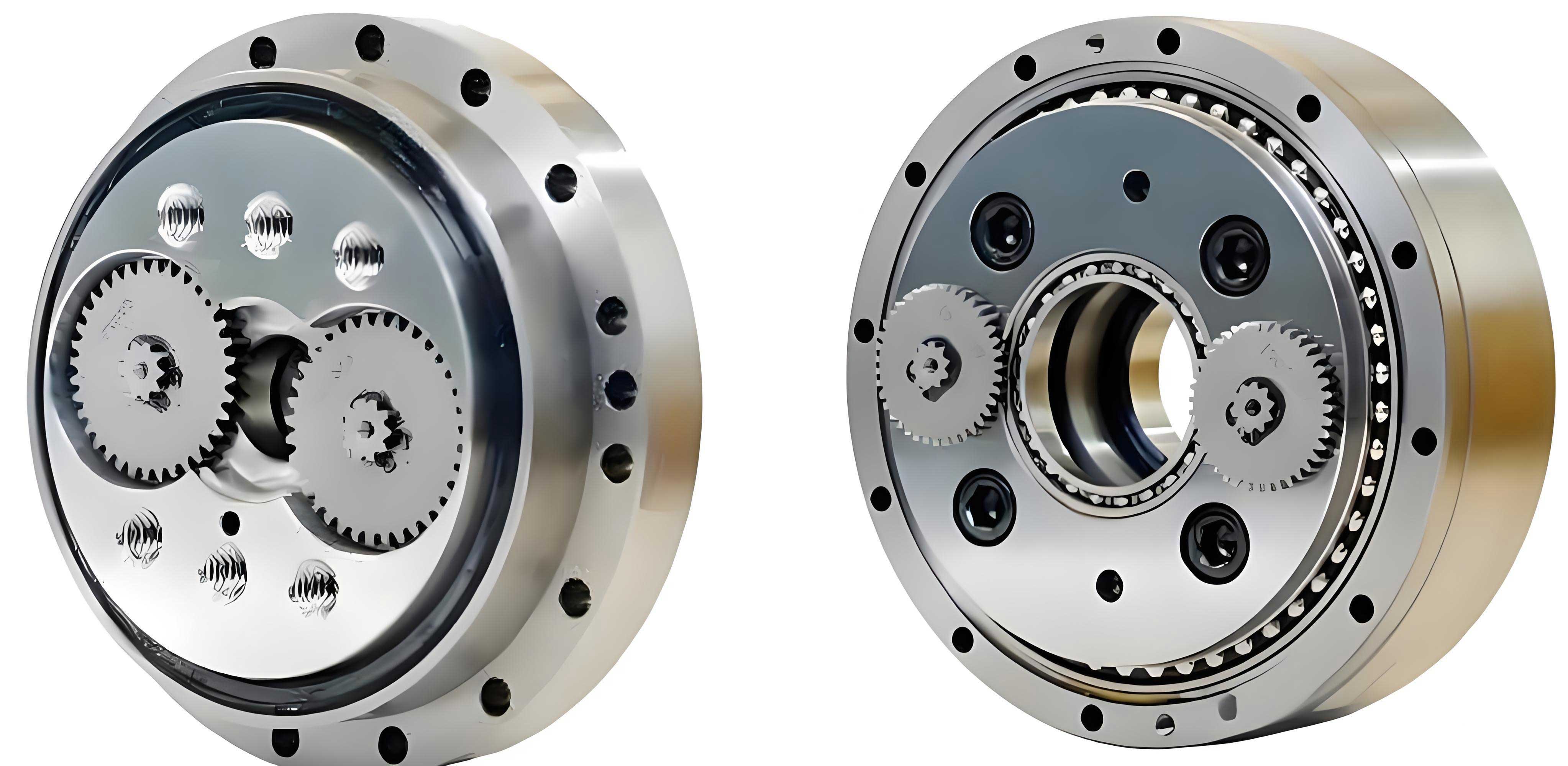
The rotary vector reducer relies on a cycloid-pinion transmission mechanism, where the cycloid gear’s tooth profile directly influences meshing characteristics, load distribution, and backlash. Standard cycloid profiles, derived from theoretical equations, are not ideal for practical applications due to the absence of clearance for lubrication and error compensation. Therefore, modification techniques are employed to alter the tooth profile during machining. Common modification methods include isometric modification (adjusting the pin radius), shift modification (adjusting the pin circle radius), and rotation modification (adjusting the phase angle). These methods can be applied individually or in combination to achieve desired gaps and tolerances. However, as highlighted in prior research, these traditional combinations often struggle to balance high load capacity with minimal backlash, necessitating exploration of new modification strategies. In our study, we focus on the eccentricity parameter, which is fundamental in forming the cycloid profile. By integrating eccentricity modification with isometric and shift modifications, we aim to enhance the performance of rotary vector reducers. This article details our methodology, from reverse engineering the gear profile to optimizing modification parameters, and presents findings that underscore the viability of the eccentricity-based combined approach.
To understand the modification methods, we first review the standard cycloid gear tooth profile equation. The profile is generated based on the relative motion between the cycloid gear and the pinion. Let \( r_p \) be the radius of the pin circle, \( r_{rp} \) be the radius of the pins, \( z_p \) be the number of pins, \( z_c \) be the number of cycloid gear teeth, \( e \) be the eccentricity, \( i_H = z_p / z_c \) be the transmission ratio, and \( \phi \) be the meshing phase angle. The standard coordinates \( (x_c, y_c) \) of the cycloid gear tooth profile are given by:
$$x_c = \left( r_p – r_{rp} S^{-1/2} \right) \cos\left( (1 – i_H) \phi \right) – \frac{e}{r_p} \left( r_p – z_p r_{rp} S^{-1/2} \right) \cos(i_H \phi)$$
$$y_c = \left( r_p – r_{rp} S^{-1/2} \right) \sin\left( (1 – i_H) \phi \right) + \frac{e}{r_p} \left( r_p – z_p r_{rp} S^{-1/2} \right) \sin(i_H \phi)$$
where \( S = 1 + k_1^2 – 2k_1 \cos \phi \) and \( k_1 = e z_p / r_p \) is the shortening factor. In modification techniques, parameters are adjusted to deviate from this standard profile. The general modified tooth profile equation, incorporating isometric modification \( \Delta r_{rp} \), shift modification \( \Delta r_p \), and rotation modification \( \delta \), is expressed as:
$$x’_c = \left( r_p + \Delta r_p – (r_{rp} + \Delta r_{rp}) S_r^{-1/2} \right) \cos\left( (1 – i_H) \phi – \delta \right) – \frac{e}{r_p + \Delta r_p} \left( r_p + \Delta r_p – z_p (r_{rp} + \Delta r_{rp}) S_r^{-1/2} \right) \cos(i_H \phi + \delta)$$
$$y’_c = \left( r_p + \Delta r_p – (r_{rp} + \Delta r_{rp}) S_r^{-1/2} \right) \sin\left( (1 – i_H) \phi – \delta \right) + \frac{e}{r_p + \Delta r_p} \left( r_p + \Delta r_p – z_p (r_{rp} + \Delta r_{rp}) S_r^{-1/2} \right) \sin(i_H \phi + \delta)$$
where \( S_r = 1 + k_1^2 – 2k_1 \cos \phi \) and \( k_1 = e z_p / (r_p + \Delta r_p) \). These modifications aim to introduce controlled gaps for lubrication and error absorption. However, as we investigate further, the eccentricity parameter \( e \) itself can be modified to influence the tooth profile. Eccentricity modification involves adjusting \( e \) to \( e + \Delta e \), which alters the shortening factor and thus the curvature of the cycloid profile. The tooth profile equation with eccentricity modification, combined with isometric and shift modifications (excluding rotation), is given by:
$$x’_{ce} = \left( r_p + \Delta r_p – (r_{rp} + \Delta r_{rp}) S’_r^{-1/2} \right) \cos\left( (1 – i_H) \phi \right) – \frac{e + \Delta e}{r_p + \Delta r_p} \left( r_p + \Delta r_p – z_p (r_{rp} + \Delta r_{rp}) S’_r^{-1/2} \right) \cos(i_H \phi)$$
$$y’_{ce} = \left( r_p + \Delta r_p – (r_{rp} + \Delta r_{rp}) S’_r^{-1/2} \right) \sin\left( (1 – i_H) \phi \right) + \frac{e + \Delta e}{r_p + \Delta r_p} \left( r_p + \Delta r_p – z_p (r_{rp} + \Delta r_{rp}) S’_r^{-1/2} \right) \sin(i_H \phi)$$
where \( S’_r = 1 + k’_1^2 – 2k’_1 \cos \phi \) and \( k’_1 = (e + \Delta e) z_p / (r_p + \Delta r_p) \). Eccentricity modification alone can cause intersection between the modified and standard profiles, but when combined with isometric and shift modifications, this issue can be mitigated. The impact of eccentricity on the rotary vector reducer is significant: reducing eccentricity decreases tooth height, increases curvature radius, shifts the meshing zone upward, and potentially enhances load-bearing capacity by increasing the lever arm. Thus, exploring eccentricity-based combinations is promising for advancing rotary vector reducer performance.
To ground our study in practical data, we performed reverse engineering on a cycloid gear from an RV-40E rotary vector reducer. The gear’s basic parameters are: \( r_p = 64 \) mm, \( r_{rp} = 3 \) mm, \( e = 1.5 \) mm, \( z_p = 40 \), and \( z_c = 39 \). We used a PMM544 coordinate measuring machine to capture the tooth profile coordinates. The measurement environment was controlled according to instrument guidelines, with the gear’s geometric center as the coordinate origin. Data points were collected at a density of 20 points per millimeter, resulting in approximately 9,300 data sets across the profile. This high-resolution measurement ensures accuracy for subsequent analysis.
The measured data represent discrete points that approximate the actual tooth profile, which consists of convex arcs, concave arcs, and transition regions. We applied the least squares method to fit circular arcs to different segments of the data. The fitting process divided the profile into three parts: convex arcs, concave arcs, and transition zones. The results are summarized in the table below, which shows the fitted radii, deviations, and error means for each segment.
| Segment Type | Fitted Radius (mm) | Upper Deviation (mm) | Lower Deviation (mm) | Fitting Gap Range (mm) | Mean Error (mm) |
|---|---|---|---|---|---|
| Concave Arc | 3.0736 | 0.00954 | -0.00605 | [0.0019, -0.0023] | 0.00264 |
| Convex Arc | 3.1229 | 0.00975 | -0.01086 | [0.0017, -0.00239] | 0.00322 |
The transition regions were analyzed separately and found not to be direct connections between arcs; instead, they exhibit smooth curves with minimal gaps. Based on the fitting, we derived an empirical equation for the cycloid gear tooth profile that closely matches the measured data. The equation is expressed as:
$$x_c = (63.9921 – 3.0075 S) \cos(-0.02564 t) – (1.29466 – 2.42779 S) \cos(1.02564 t)$$
$$y_c = (63.9921 – 3.0075 S) \sin(-0.02564 t) + (1.29466 – 2.42779 S) \sin(1.02564 t)$$
where \( S = (1.65491 – 1.61852 \cos t)^{-1/2} \) and \( t \) is a parameter related to the meshing phase angle. This equation approximates the actual tooth profile with high precision, achieving errors less than 2 μm in transition zones and under 1.6 μm in arc regions. We use this equation as the target profile curve for optimizing modification methods, as it represents a realistic, high-accuracy cycloid gear from a rotary vector reducer.
With the target profile established, we proceed to optimize the modification parameters. Our goal is to minimize the deviation between the modified tooth profiles and the target curve. We consider three combined modification methods: (1) isometric and shift modification, (2) isometric, shift, and rotation modification, and (3) isometric, shift, and eccentricity modification. For each method, we define an objective function based on the average absolute deviation in the x-coordinate across discrete points along the profile. Let \( (x_{ci}, y_{ci}) \) be coordinates from the target curve for \( i = 1, 2, \dots, m \), where \( \phi \) is sampled over \( [0, 2\pi] \). For a given modification method, we compute the modified coordinates \( (x’_{ci}, y’_{ci}) \) or \( (x’_{cei}, y’_{cei}) \) such that \( y’_{ci} = y_{ci} \) or \( y’_{cei} = y_{ci} \), solve for the corresponding phase angle, and then find the x-coordinate deviation. The objective functions are:
For isometric, shift, and rotation modification:
$$F_1(\Delta r_p, \Delta r_{rp}, \delta) = \frac{1}{m} \sum_{i=1}^{m} | x’_{ci} – x_{ci} |$$
For isometric, shift, and eccentricity modification:
$$F_2(\Delta r_p, \Delta r_{rp}, \Delta e) = \frac{1}{m} \sum_{i=1}^{m} | x’_{cei} – x_{ci} |$$
We employ a genetic algorithm, a global optimization technique inspired by natural selection, to minimize these functions. The algorithm efficiently explores the parameter space to find optimal modification amounts. The optimization results are presented in the following table, comparing the three methods.
| Modification Method | Isometric Modification (mm) | Shift Modification (mm) | Rotation Modification (°) | Eccentricity Modification (mm) | Average Deviation (mm) |
|---|---|---|---|---|---|
| Isometric + Shift | 0.0247 | -0.1763 | – | – | 0.4393 |
| Isometric + Shift + Rotation | -0.3578 | -0.2688 | 0.1010 | – | 0.1542 |
| Isometric + Shift + Eccentricity | 0.0141 | -0.0401 | – | -0.2073 | 0.0356 |
The results clearly show that the combined modification of isometric, shift, and eccentricity yields the smallest deviation (0.0356 mm) from the target profile, outperforming the other two methods. This indicates that the eccentricity-based approach better approximates the actual high-precision cycloid gear profile. Visual comparisons of the optimized profiles further confirm that the eccentricity combination maintains close alignment across the entire tooth, including the tip and root regions, whereas the other methods exhibit noticeable deviations in these areas. Thus, the feasibility of incorporating eccentricity modification into rotary vector reducer design is supported by our optimization analysis.
In conclusion, our study addresses the challenge of achieving both high load capacity and low backlash in rotary vector reducers through cycloid gear tooth profile modification. By reverse engineering an RV-40E reducer gear and fitting an accurate profile equation, we established a target for optimization. We proposed a novel combined modification method that includes eccentricity adjustment along with isometric and shift modifications. Using genetic algorithm optimization, we demonstrated that this method produces a tooth profile with minimal deviation from the target, surpassing traditional combinations like isometric-shift and isometric-shift-rotation. This finding highlights the potential of eccentricity-based modifications to enhance the performance of rotary vector reducers in precision applications. Future work could involve experimental validation, dynamic analysis, and extension to other reducer models. Our research contributes to the ongoing development of advanced transmission systems, underscoring the importance of innovative modification strategies in rotary vector reducer technology.
The rotary vector reducer remains a focal point in precision engineering, and our exploration of eccentricity modification opens new avenues for optimization. By integrating this parameter into combined modification schemes, manufacturers can potentially achieve superior balancing of mechanical properties. We encourage further studies to refine modification amounts and assess long-term performance in real-world rotary vector reducer applications. As automation and robotics demand ever-higher accuracy, such advancements will be crucial for next-generation transmission solutions.