
In my engineering practice, I treat a building’s HVAC system and the precision transmission elements inside it as one connected problem. I do not isolate the selection of a screw gear from the thermal, acoustic, and operating profile of the building, because the screw gear is often the hidden element that determines whether a compressor, fan drive, pump drive, or air-handling unit can hold its intended performance over thousands of operating hours. When I review an HVAC design, I therefore ask three questions at the same time: how much energy the system will consume, how well it can be adjusted, and how reliably each rotating component will transmit torque. The screw gear sits at the center of the third question, and it influences the first two through efficiency, vibration, backlash, and service life.
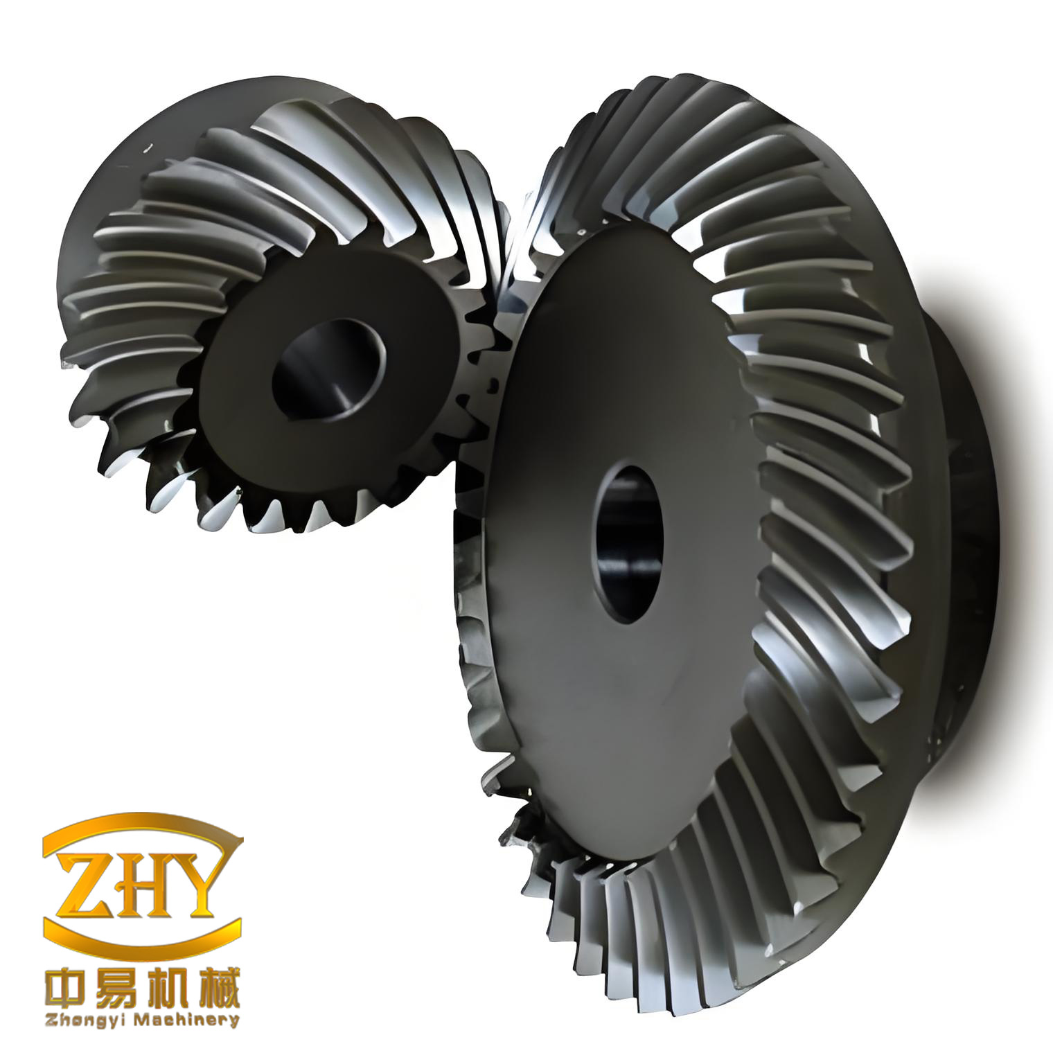
My integrated view of HVAC design and screw gear manufacturing
I begin with the principle that an HVAC system must be both buildable and operable. A design that looks efficient on paper but cannot be manufactured, tuned, or maintained is not a good design. In the same way, a screw gear that achieves a theoretical profile but cannot be produced with stable heat treatment, grinding, and inspection is not a practical screw gear. I connect these two worlds by using a common language of tolerances, duty cycles, and life-cycle cost. The screw gear is not an accessory in this language; it is a critical transmission element that converts motor speed and torque into the pressure and flow required by the HVAC process.
| Design domain | Primary goal I set | Critical constraint | How the screw gear enters the decision |
|---|---|---|---|
| HVAC thermal comfort | Maintain temperature and humidity within set limits | Load variation and part-load operation | The screw gear affects compressor and fan drive speed stability |
| HVAC energy efficiency | Minimize annual energy use | COP, fan power, pump power | The screw gear’s efficiency changes transmitted power loss |
| HVAC maintainability | Reduce downtime and service cost | Access, spare parts, lubrication | The screw gear’s wear and backlash determine service interval |
| HVAC controllability | Match capacity to real-time demand | Sensor accuracy and actuator response | The screw gear must transmit motion without excessive lost motion |
| Screw gear manufacturing | Produce accurate, durable toothed surfaces | Heat treatment distortion, tool wear, machine stiffness | Every process step changes final contact pattern and noise |
| Screw gear precision | Control profile, lead, pitch, and backlash | Metrology and compensation | Precision directly influences HVAC vibration and efficiency |
I use a simple energy balance to keep the HVAC side visible. For a cooling coil or heat exchanger, the heat transfer rate is
$$Q = U A \Delta T_m$$
where \(Q\) is the heat transfer rate, \(U\) is the overall heat transfer coefficient, \(A\) is the heat transfer area, and \(\Delta T_m\) is the mean temperature difference. For a refrigeration cycle, I track the coefficient of performance as
$$COP = \frac{Q_c}{W_{in}}$$
For a fan or pump, the shaft power is approximately
$$P = \frac{\dot V \Delta p}{\eta_{total}}$$
where \(\dot V\) is volume flow rate, \(\Delta p\) is pressure rise, and \(\eta_{total}\) is the combined hydraulic, mechanical, and motor efficiency. A screw gear inside the drive train contributes to \(\eta_{total}\) through mesh loss, bearing loss, and sealing loss. When I reduce those losses, I improve the HVAC system’s annual energy performance, not only the gearbox performance.
HVAC design requirements I apply before selecting a screw gear
I never choose a screw gear before I understand the load profile. An office building may operate only during daytime, while a data center may operate continuously. A hospital may require simultaneous heating and cooling. These operating patterns determine the required turndown ratio, the number of starts, and the acceptable noise level. The screw gear must then be selected with a duty cycle that matches this reality. I express the part-load energy factor as
$$PLEF = \frac{\sum_{i=1}^{n} P_i t_i}{\sum_{i=1}^{n} P_{full} t_i}$$
where \(P_i\) is power at part-load condition \(i\), \(t_i\) is the time spent at that condition, and \(P_{full}\) is full-load power. A screw gear with high efficiency only at full load may be a poor choice if the HVAC system spends most of its time at 40% to 60% load.
| HVAC requirement | Metric I use | Design response | Screw gear implication |
|---|---|---|---|
| Energy efficiency | COP, kW/ton, PLEF | Variable-speed drives and high-efficiency components | Lower mesh loss and stable lubrication |
| Operational cost | Annual operating cost | Part-load optimization | Efficient screw gear at partial torque |
| Initial cost | First cost | Right-sizing, not oversizing | Simpler screw gear geometry where acceptable |
| Maintainability | Mean time to repair | Accessible components and condition monitoring | Replaceable screw gear sets and inspection ports |
| Service life | Design life in hours | Material and heat treatment selection | Case depth, core hardness, and surface finish |
| Adjustability | Turndown ratio | VAV, VRV, or variable-speed control | Backlash control and low lost motion |
| Acoustics | Sound power level | Vibration isolation and smooth tooth contact | Lead and profile correction of the screw gear |
| Automation | Control stability | Sensors, PID, building management system | Repeatable transmission for actuator and damper drives |
For variable-air-volume and variable-refrigerant-flow systems, I compare the two main options because both depend on precise motion control. In my experience, the screw gear and its backlash are often overlooked when engineers compare only the HVAC schematic.
| Comparison item | VRV system | VAV system | My screw gear note |
|---|---|---|---|
| Energy performance | Good part-load performance with variable-speed compressor | Good part-load performance with variable fan and terminal boxes | The screw gear must tolerate frequent speed changes |
| Initial cost | High equipment cost | Moderate to high depending on ductwork | High-precision screw gear adds cost but reduces noise |
| Controls | Refrigerant flow and compressor speed | Airflow and damper position | Actuator screw gear backlash affects damper hunting |
| Maintenance | Refrigerant circuit expertise | Filter, belt, and damper maintenance | Lubrication and wear inspection of the screw gear |
| Best fit | Zoned buildings with varied occupancy | Large open spaces with central air handling | I match screw gear life to the building use schedule |
I also apply automatic control because an HVAC system that cannot modulate will waste energy. A general PID control law is
$$u(t) = K_p e(t) + K_i \int_{0}^{t} e(\tau)d\tau + K_d \frac{de(t)}{dt}$$
where \(e(t)\) is the error between setpoint and measured value. If the screw gear has excessive backlash, the actuator may overshoot, and the controller may oscillate. The result is not only discomfort but also unnecessary wear. Thus, I specify backlash limits for screw gear pairs used in valves, dampers, and variable-geometry mechanisms.
Why the screw gear is central to reliable HVAC transmission
A screw gear, also called a helical gear in many transmission contexts, uses inclined teeth to transmit motion between shafts. In HVAC equipment, I encounter screw gear arrangements in compressor drive trains, cooling tower fan drives, pump reducers, air-handling unit fan drives, and damper actuators. The screw gear’s gradual tooth engagement gives it a high overlap ratio, which reduces impact and noise. This is particularly valuable in occupied buildings where acoustic comfort is part of the HVAC specification. The same screw gear can also carry high torque in a compact envelope, which helps me reduce the size and weight of the drive package.
I use the following geometry relationships when I review a screw gear design. The transverse pitch diameter is
$$d = \frac{m_n z}{\cos \beta}$$
where \(m_n\) is the normal module, \(z\) is the number of teeth, and \(\beta\) is the helix angle. The lead of the screw gear is
$$p_z = \frac{\pi d}{\tan \beta}$$
The transmission ratio for a screw gear pair is
$$i = \frac{n_1}{n_2} = \frac{z_2}{z_1}$$
where \(n_1\) and \(n_2\) are rotational speeds. The axial force generated by the helix is
$$F_a = F_t \tan \beta$$
where \(F_t\) is the tangential force. This axial force is one reason I pay close attention to bearing selection and housing stiffness. A screw gear with a large helix angle may offer smooth motion, but it also imposes a larger axial load on the shaft system.
| Symbol | Meaning | Typical HVAC relevance |
|---|---|---|
| \(m_n\) | Normal module | Tooth size and load capacity |
| \(z\) | Number of teeth | Speed ratio and pulsation frequency |
| \(\beta\) | Helix angle | Noise, axial force, overlap ratio |
| \(d\) | Pitch diameter | Center distance and housing size |
| \(p_z\) | Lead | Axial motion and machining setup |
| \(F_t\) | Tangential force | Torque transmission |
| \(F_a\) | Axial force | Bearing load and housing deflection |
| \(\varepsilon_\gamma\) | Total contact ratio | Motion smoothness and noise |
The total contact ratio of a screw gear pair can be written as
$$\varepsilon_\gamma = \varepsilon_\alpha + \varepsilon_\beta$$
where \(\varepsilon_\alpha\) is the transverse contact ratio and \(\varepsilon_\beta\) is the overlap ratio. I aim for sufficient overlap so that load transfer is gradual. In HVAC applications, this reduces excitation at the gear mesh frequency, which can otherwise propagate through the ductwork or building structure.
Screw gear manufacturing methods I evaluate
I evaluate several manufacturing routes for a screw gear before releasing a process plan. The choice depends on batch size, accuracy grade, material, heat treatment, and the final contact pattern required by the HVAC drive. The main methods I consider are the unified cutter method, hard tooth surface lapping, hard tooth surface grinding, generating grinding, and CNC precision machining.
| Method | Principle I use | Strength | Limitation | Best application for a screw gear |
|---|---|---|---|---|
| Unified cutter method | Tilt the cutter while keeping its center fixed | Simple operation on universal machines | Not efficient for high-volume precision screw gear production | Small batches of spiral bevel, hypoid, and zero-degree screw gear parts |
| Hard tooth surface lapping | Run mating gears with abrasive compound | Reduces roughness and improves contact | Difficult to keep rolling uniform along the whole tooth | Final finishing of hardened screw gear pairs |
| Hard tooth surface grinding | Grind hardened teeth by generating or forming | High accuracy and good surface finish | Requires rigid machines and thermal control | High-precision screw gear for low-noise HVAC drives |
| Generating method | Tool and workpiece perform conjugate rolling | Accurate involute and lead | Setup depends on helix angle and tool geometry | Screw gear with varying helix or high contact requirements |
| CNC precision machining | Multi-axis interpolation of tool path | Flexible geometry and compensation | Programming and machine cost | Complex screw gear profiles and small-batch optimization |
In the unified cutter method, I tilt the cutter to maintain rigidity while keeping the cutter center unchanged. This is useful for small-batch production because it simplifies setup. However, when I need a screw gear with high accuracy and repeatability, I move toward generating grinding or CNC precision machining. The screw gear’s tooth surface is a complex surface, and the selected method must control profile, lead, and pitch simultaneously.
Hard tooth surface lapping is a traditional process that I still use for some screw gear pairs because it can reduce surface roughness and correct minor tooth form and lead errors. The challenge is that the two teeth are in a free-fitting state during lapping. The rolling amount is not uniform: the tooth root and tooth tip tend to roll more, while the pitch region rolls less. If I allow lapping to run too long, the screw gear tooth form can degrade. Therefore, I program cyclic changes in mounting distance, offset, and shaft angle to distribute the rolling action more evenly.
Hard tooth surface grinding gives me better control. Generating grinding uses a tool that rolls with the screw gear in a conjugate motion. The tool and the workpiece maintain a specific speed ratio, and the tool generates the enveloping surface of the screw gear. Forming grinding uses CAD, CNC, and material technology to move from numerical model to manufacture. Because the active screw gear often has a different tooth slot cross-section along its length, generating grinding is usually necessary for the driving member. I use forming methods where the geometry permits, but I do not force a forming process onto a screw gear that demands conjugate generation.
My screw gear process flow
I organize screw gear manufacturing into rough machining, heat treatment, semi-finish machining, and finish machining. Each stage has a distinct purpose, and each stage creates constraints for the next. I do not treat heat treatment as a black box, because the distortion it creates must be anticipated in the roughing allowance and corrected in the finishing operation.
| Stage | Purpose | Key process | Critical parameter | Screw gear quality effect |
|---|---|---|---|---|
| Rough machining | Remove excess stock | Layer cutting, section line, equidistant cutting, drilling | Allowance and tool path | Prepares stable stock for heat treatment |
| Heat treatment | Improve core and surface properties | Quenching, nitriding, carburizing, tempering | Temperature, time, atmosphere | Controls hardness, residual stress, and distortion |
| Semi-finish | Remove heat-treatment effects and leave uniform stock | Ball-nose contour milling, classification, correction | Tool diameter and axial orientation | Reduces interference and prepares contact pattern |
| Finish machining | Meet drawing accuracy and surface finish | Lapping, grinding, generating, CNC finishing | Backlash, lead, profile | Determines noise, life, and efficiency of the screw gear |
For rough machining, I often use layer cutting because the tool path is controlled in a two-dimensional plane. This reduces the programming burden and helps me avoid empty cuts. When I prepare a screw gear for hobbing, I control the tooth thickness so that the finishing allowance per flank remains small. I typically keep the single-side grinding allowance within a controlled range, and I limit runout to avoid uneven case depth after heat treatment. Uneven case depth is dangerous because it produces uneven wear resistance, and a screw gear with uneven hardness will not maintain its contact pattern.
For heat treatment, I calculate the thermal expansion as
$$\Delta L = \alpha L \Delta T$$
where \(\alpha\) is the coefficient of thermal expansion, \(L\) is the original length, and \(\Delta T\) is the temperature change. The thermal stress can be estimated as
$$\sigma = E \alpha \Delta T$$
where \(E\) is the elastic modulus. During quenching, the surface and core cool at different rates, so the screw gear can distort. I reduce this risk by uniform heating, stepped heating, or controlling the heating rate. A heating rate in the range of \(150\,^\circ C/h\) to \(200\,^\circ C/h\) is often useful for limiting the temperature difference between surface and core. I also specify sufficient tempering to relieve residual stress. In carburizing, I control the case carbon content and depth because excessive case carbon can cause surface spalling during semi-finishing. After carburizing, I use forced air cooling where appropriate to suppress network carbides and ferrite.
| Heat treatment variable | My target or range | Reason | Screw gear consequence if ignored |
|---|---|---|---|
| Heating rate | \(150\,^\circ C/h\) to \(200\,^\circ C/h\) | Reduce surface-to-core temperature difference | Distortion and cracking |
| Carburizing atmosphere | Controlled carbon potential | Avoid excess case carbon | Surface spalling and poor finish |
| Case depth | Based on load and module | Balance wear resistance and toughness | Premature pitting or tooth breakage |
| Tempering | Sufficient time and temperature | Relieve residual stress | Dimensional instability after finishing |
| Cooling | Controlled forced air where needed | Suppress network carbides | Brittle screw gear surface |
During semi-finishing, I remove the material affected by heat treatment and establish a uniform stock for finishing. Because the screw gear tooth surface is a complex curved surface, I use a ball-nose tool to contour the two flanks of the tooth slot. For the driving screw gear produced by a forming method, the tooth surface may be a ruled surface. I adjust the tool axis direction and tool size to avoid interference. I also select a smaller tool diameter when the chip volume must be reduced. In high-volume production, I classify screw gears by size, side clearance, and contact position before semi-finishing. This classification lets me correct the lapping machine settings for each group. It also helps me detect a defective screw gear before it damages a mating gear or the fixture.
Finish machining is where I set the final screw gear quality. Lapping is a reliable finishing method for hardened screw gear teeth. It removes residual stress and heat-treatment distortion, improves the contact area, and helps the screw gear meet the design contact pattern. During lapping, I keep the clearance variation smaller than in semi-finishing so that the side clearance does not become too small. If one member of a screw gear pair is rejected, a good member can sometimes be matched with a new member and lapped again. However, I still verify the new pair with an unlaunched reference to confirm contact and backlash. The defects I watch for in lapping are interference at the tooth tip and root, excessively long contact, and diagonal contact. These can be controlled by understanding the process, adjusting braking load, lapping time, and machine side clearance.
| Lapping defect | Where it appears | Likely cause | My corrective action |
|---|---|---|---|
| Tip-root contact | Tooth tip and root | Incorrect mounting distance or tooth depth | Adjust mounting distance and verify tooth thickness |
| Excessively long contact | Across full tooth | Too much lapping load or time | Reduce lapping time and braking load |
| Diagonal contact | Across flank diagonally | Shaft angle or offset error | Correct offset and shaft angle |
| Interference | Local flank region | Tool path or heat-treatment distortion | Recheck semi-finish stock and correction curve |
| Backlash variation | Around the screw gear | Runout or pitch error | Inspect runout and classify the screw gear |
Precision machining of the screw gear
When I need the highest precision, I use generating methods and CNC methods. In generating precision machining, the tool installation angle changes periodically according to the screw gear helix angle. The tool and workpiece perform a conjugate rolling motion. The tool installation angle and the screw gear helix angle have a linear relationship in many setups. I adjust the machine so that the pitch surface of the workpiece and the pitch surface of the imaginary plane gear roll without sliding. The involute profile and the helix angle follow the designed variation. Because the hobbing principle depends on conjugate motion between the tool and the screw gear, the tool installation angle must align with the screw gear helix line. For a variable-helix screw gear, each tooth may have a different helix angle. I then keep one end of the tool fixed and swing the other end according to the helix variation.
I express the tool setting relationship in a general form as
$$\Sigma = \beta_g \pm \lambda_t$$
where \(\Sigma\) is the installation angle, \(\beta_g\) is the screw gear helix angle, and \(\lambda_t\) is the tool lead angle. The sign depends on the hand of the helix and the tool. I verify this relationship on the machine before cutting, because a small angular error changes the contact pattern along the tooth lead.
In CNC precision machining, I use multi-axis interpolation. The machine can control three or more axes simultaneously. The screw gear angle changes according to a defined law, so the tool and workpiece perform a relative swinging motion. The more联动 axes I use, the more complex the tooth surface I can generate and the higher the potential accuracy. In a typical setup, the tool is fixed on the Z-axis and moves vertically. The fixture performs the swinging motion. To control accuracy and maintain coaxiality, the fixture may move in the X and Y directions. Because each tooth may have a different lead due to helix variation, I control the tool path by program according to the helix change law.
| Machine axis | Motion I assign | Purpose | Screw gear quality influence |
|---|---|---|---|
| X-axis | Fixture translation | Radial position and correction | Profile and tooth thickness |
| Y-axis | Fixture translation | Offset and centering | Contact pattern location |
| Z-axis | Tool vertical motion | Depth and feed | Tooth depth and root clearance |
| Swing axis | Fixture or tool rotation | Helix generation | Lead accuracy and smoothness |
| Spindle axis | Workpiece rotation | Indexing and conjugate motion | Pitch accuracy and backlash |
I use the following parametric representation when I program a CNC path for a screw gear tooth surface:
$$x(t) = \rho(t)\cos\theta(t)$$
$$y(t) = \rho(t)\sin\theta(t)$$
$$z(t) = p_z \frac{\theta(t)}{2\pi}$$
Here \(p_z\) is the lead of the screw gear, and \(\theta(t)\) is the angular parameter. This representation helps me synchronize the rotary and linear axes. I then apply compensation for tool radius, machine geometry, and thermal drift. The goal is not only to cut the nominal screw gear geometry but also to produce a contact pattern that remains stable under load.
Quality control and inspection of the screw gear
I inspect a screw gear at several stages because final inspection alone cannot reveal whether the process is capable. I check the raw material, the rough-machined geometry, the heat-treatment response, the semi-finished stock, and the finished tooth surface. The most important characteristics are profile error, lead error, pitch error, runout, backlash, contact pattern, and surface roughness. I also verify hardness and case depth when the screw gear is heat treated.
| Inspection item | Instrument or method | Why I measure it | Effect on HVAC operation |
|---|---|---|---|
| Profile error | Gear measuring center | Controls conjugate action | Noise and vibration |
| Lead error | Lead measuring instrument | Controls axial contact | Load concentration and wear |
| Pitch error | Indexing inspection | Controls rotational uniformity | Torque pulsation |
| Runout | Dial indicator or CMM | Controls eccentricity | Backlash variation and noise |
| Backlash | Dial indicator with fixture | Controls lost motion | Control hunting in dampers and valves |
| Contact pattern | Marking compound | Shows load distribution | Service life and pitting resistance |
| Surface roughness | Profilometer | Controls friction and lubrication | Efficiency and heat generation |
| Hardness and case depth | Hardness tester and micrograph | Confirms heat treatment | Wear and fatigue life |
I use a capability index to decide whether the screw gear process is stable:
$$C_p = \frac{USL – LSL}{6\sigma}$$
$$C_{pk} = \min\left(\frac{USL – \mu}{3\sigma}, \frac{\mu – LSL}{3\sigma}\right)$$
where \(USL\) and \(LSL\) are the upper and lower specification limits, \(\mu\) is the process mean, and \(\sigma\) is the process standard deviation. For a screw gear used in an HVAC drive, I prefer \(C_{pk}\) values that show the process is centered and capable. If the screw gear lead error is not capable, I correct the machine or modify the process before increasing production.
Linking HVAC design requirements to screw gear tolerances
I make the connection between HVAC performance and screw gear tolerance explicit. A chilled-water pump drive may tolerate more backlash than a damper actuator, but it may require higher torque capacity and better lubrication. A cooling tower fan drive may tolerate some noise at the fan, but the screw gear must handle outdoor temperature variation and sustained load. A compressor drive may require very low vibration because the compressor itself is sensitive to torque ripple. I therefore build a requirements matrix and use it to set screw gear accuracy grades.
| HVAC application | Dominant requirement | Screw gear characteristic I specify | Reason |
|---|---|---|---|
| Centrifugal compressor drive | Low vibration and high efficiency | Tight lead and profile tolerance, balanced assembly | Prevents excitation at mesh frequency |
| Screw compressor drive | High torque and stable oil film | Proper helix angle, case depth, surface finish | Carries load without scuffing |
| Fan drive | Moderate noise and long life | Controlled backlash and contact pattern | Reduces wear during continuous operation |
| Pump drive | Efficiency and corrosion resistance | Material selection and heat treatment | Maintains performance in wet environments |
| Damper actuator | Low lost motion | Minimum backlash and high repeatability | Improves control stability |
| Valve actuator | Accurate positioning | Stiffness and low hysteresis | Prevents overshoot and hunting |
I also consider the effect of temperature on the screw gear. HVAC equipment may operate from cold ambient conditions to hot mechanical rooms. The thermal expansion of the housing, shaft, and screw gear can change backlash. I estimate the backlash change as
$$\Delta j = \Delta \alpha L \Delta T$$
where \(\Delta \alpha\) is the difference in thermal expansion coefficients, \(L\) is the relevant length, and \(\Delta T\) is the temperature change. If the housing and the screw gear have different materials, the operating backlash may be much smaller or larger than the assembly backlash. I therefore specify assembly backlash with the operating temperature in mind.
Optimization of the combined system
I optimize the HVAC system and the screw gear together using a weighted objective function. The variables include equipment capacity, screw gear accuracy grade, heat treatment, surface finish, and control strategy. The objective is to minimize life-cycle cost while satisfying comfort, reliability, and acoustic constraints. I write a simplified objective as
$$\min f = w_1 C_{cap} + w_2 C_{op} + w_3 E_{trans} + w_4 E_{HVAC} + w_5 M + w_6 D$$
Here \(C_{cap}\) is capital cost, \(C_{op}\) is operating cost, \(E_{trans}\) is transmission energy loss, \(E_{HVAC}\) is HVAC energy use, \(M\) is maintenance cost, and \(D\) is downtime cost. The weights \(w_1\) to \(w_6\) reflect the owner’s priorities. I treat the screw gear as a variable that changes \(E_{trans}\), \(M\), and \(D\). A higher-precision screw gear may increase \(C_{cap}\), but it can reduce \(E_{trans}\), \(M\), and \(D\). In many projects, the life-cycle optimum is not the lowest-cost screw gear.
| Decision variable | Low-cost choice | High-performance choice | My typical balance |
|---|---|---|---|
| Screw gear accuracy grade | Commercial grade | Precision ground | Precision for compressors and actuators |
| Heat treatment | Through hardened | Case carburized and ground | Case carburized for high-load screw gear |
| Surface finish | As machined | Lapped or ground | Ground and lapped for low noise |
| Backlash | Loose | Controlled minimum | Tight for control, moderate for power drives |
| Lubrication | Manual | Automated and monitored | Automated for inaccessible screw gear |
| Inspection | Sampling | 100% critical features | Critical features checked on every screw gear |
My conclusions from practice
From my perspective, the screw gear is a decisive component in HVAC reliability because it silently determines how well rotational power becomes useful flow and pressure. I do not separate the thermal design from the mechanical design, and I do not separate the screw gear drawing from the manufacturing process. A screw gear that is designed without considering heat treatment distortion will be difficult to finish. A screw gear that is manufactured without considering the HVAC duty cycle may be accurate but short-lived. A screw gear that is selected without considering control backlash may cause the HVAC system to hunt. Therefore, I use the following rules in my work.
First, I define the HVAC load profile before I define the screw gear life. The screw gear must match the hours of operation and the part-load behavior. Second, I select the screw gear geometry with the helix angle, contact ratio, and axial force in mind. A smooth screw gear is not automatically the best screw gear if the axial force overloads the bearings. Third, I design the manufacturing process around the heat treatment. Rough machining, semi-finishing, and finishing must all leave the correct allowance for distortion. Fourth, I inspect the screw gear with the same seriousness as the HVAC performance. Profile, lead, pitch, backlash, and contact pattern are not secondary details; they are the physical basis of quiet and efficient operation. Fifth, I integrate the screw gear with automatic control. The controller cannot compensate for a screw gear with excessive lost motion, so I specify backlash that is appropriate for the loop.
I also keep the following formula in mind as a compact statement of the design aim:
$$\eta_{system} = \eta_{HVAC} \cdot \eta_{drive} \cdot \eta_{screw\,gear} \cdot \eta_{control}$$
If any factor is poor, the entire system efficiency falls. The screw gear term \(\eta_{screw\,gear}\) may look small, but over a year of continuous operation it becomes significant. I therefore treat screw gear efficiency, screw gear life, and screw gear precision as first-order HVAC design parameters. When I apply this integrated approach, I obtain systems that are easier to build, easier to operate, and easier to maintain. The screw gear is not merely a part in the machine; it is a point where thermal design, mechanical design, manufacturing process, and control strategy meet. That is why I continue to study the screw gear with the same attention I give to the HVAC load calculation.
| Practice rule I follow | HVAC benefit | Screw gear benefit |
|---|---|---|
| Start from the load profile | Right-sized equipment | Correct duty cycle and life |
| Control helix angle and axial force | Stable fan and pump operation | Balanced bearing load |
| Plan heat treatment allowance | Fewer field failures | Less distortion and scrap |
| Measure profile, lead, and backlash | Low noise and stable control | Predictable contact pattern |
| Match backlash to control loop | Reduced hunting and overshoot | Lower lost motion |
| Use life-cycle optimization | Lower annual cost | Better material and finishing choices |
| Integrate condition monitoring | Fewer unexpected shutdowns | Early wear detection |
In the end, I judge a screw gear by how it behaves in the assembled HVAC system, not only by how it looks on a coordinate measuring machine. The screw gear must transmit torque smoothly, hold its contact pattern under load, resist wear after heat treatment, and remain within backlash limits across the operating temperature range. When those conditions are met, the HVAC system can achieve its intended comfort, efficiency, and acoustic performance. That is the standard I apply to every screw gear and every HVAC design I touch.