
In the manufacturing of hypoid gears, achieving a controlled and optimal contact pattern is paramount for ensuring smooth operation, high load capacity, and minimal noise. Traditional adjustment methods for the semi-generating cutting process often rely on calculation reference points that do not coincide with the center of the final contact ellipse, introducing inherent theoretical errors into the setup. This article presents a comprehensive new methodology for the adjustment calculations in the tilted-cutter semi-generating process for hypoid gears. The core innovation lies in fundamentally shifting the calculation reference point to the center of the target contact area, thereby eliminating a significant source of error present in established methods. Furthermore, this approach introduces refinements in the calculation of the pinion root angle correction, incorporates tooth profile curvature modifications, and significantly simplifies the geometric parameter calculations for the generating gear. The collective result is a method that promises to reduce gear setup time and substantially improve the quality of gear meshing for hypoid gears.
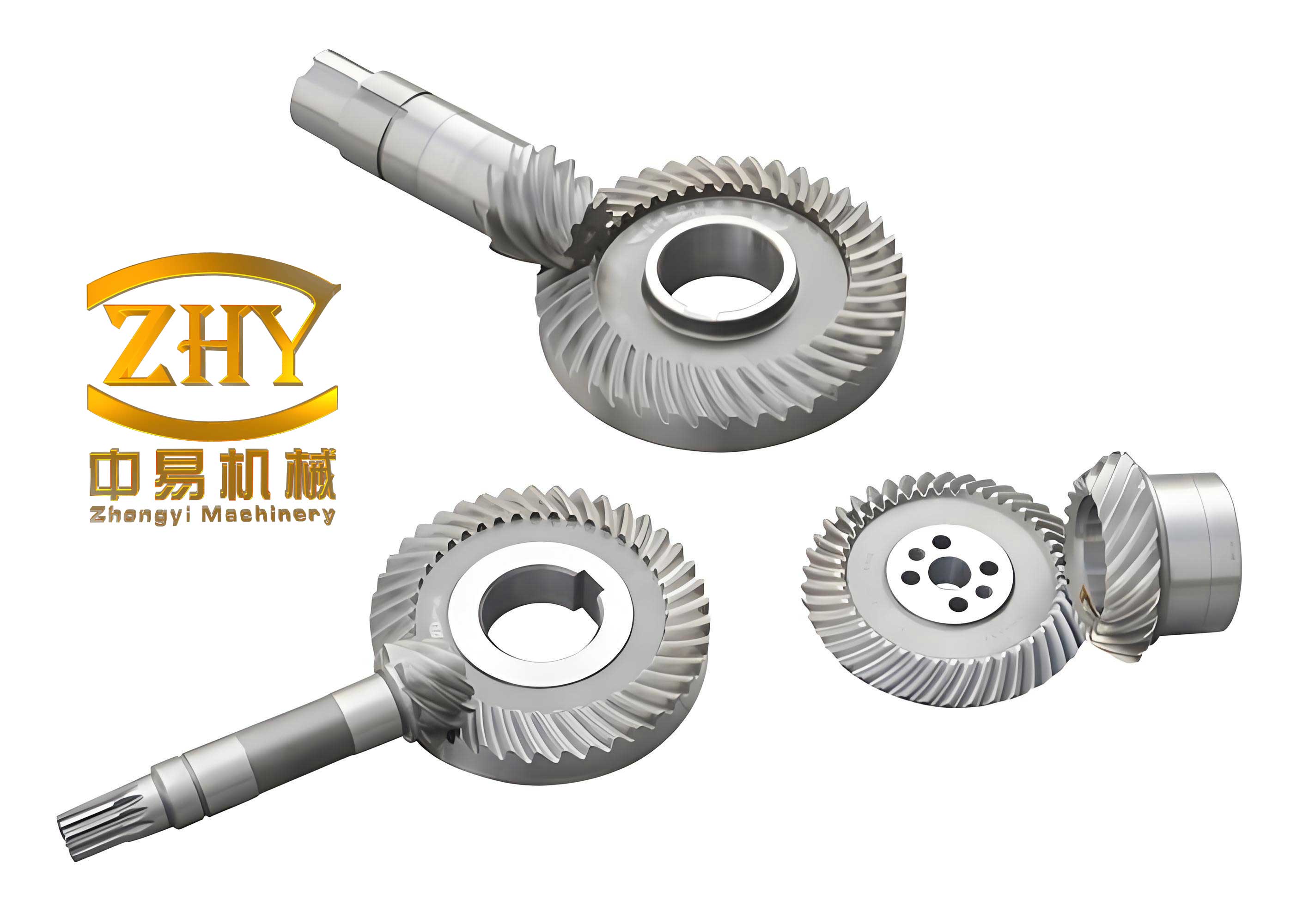
The process described here involves form-cutting the gear (larger member) and generating the pinion (smaller member) using a tilted cutter head. The fundamental principle is to construct a system of imaginary gears whose meshing conditions at a specifically chosen point dictate the machine settings. For the gear, the calculation reference point P_g is taken at the midpoint of the tooth space on the pitch cone. For the pinion, the critical point M_0 is the point on the equidistant surface of the cutter that corresponds to the center of the desired contact pattern on the pinion tooth surface. A hypothetical pinion G_1 is defined to be in mesh with the generating gear (cradle) C at this point M_0. The geometric parameters of G_1 and the curvature properties of its surface at M_0 become the foundation for all subsequent calculations. The methodology can be systematically broken down into three main stages.
Stage 1: Geometric Parameters of the Imaginary Pinion G1
Based on the initial gear design data and the chosen contact center, the geometric parameters of the imaginary pinion G_1 are calculated. Its pitch cone is defined to ensure proper meshing at point M_0. A key parameter is the pinion cutting root angle $\delta_{1a}$, which is adjusted from the theoretical root angle $\delta_{1f}$ by a correction $\Delta \delta$ to compensate for machining errors caused by the flat top of the cutter head not matching the crown gear’s apex cone.
$$ \delta_{1a} = \delta_{1f} \pm \Delta \delta $$
The upper sign is for the concave side, the lower for the convex side of the hypoid gear pinion. The correction $\Delta \delta$ is approximated by:
$$ \Delta \delta = \frac{r_{c0} \cdot \sin(\delta_0)}{R_{m1} \cdot \cos(\delta_{1a})} \cdot \left( \frac{\cos(\delta_0 \mp \phi_{n0})}{\cos \phi_{n0}} – 1 \right) $$
Where $\delta_0$ is the generating gear’s pitch angle, $\phi_{n0}$ is the normal pressure angle, $r_{c0}$ is the cutter radius, and $R_{m1}$ is the mean cone distance of the pinion. Unlike traditional methods which assume $\delta_0 = 75^\circ$, this method uses the actual calculated value of $\delta_0$, determined iteratively.
Further essential parameters at point M_0 are determined:
- Pressure angle $\alpha_{n1}$: $$ \alpha_{n1} = \arctan(\tan \alpha_{n0} \cdot \cos(\gamma_m \pm \theta_1) \mp \tan \beta_{m1} \cdot \sin(\gamma_m \pm \theta_1)) $$
- Spiral angle $\beta_{m1}$: $$ \beta_{m1} = \arcsin(\sin \beta_{m0} \cdot \cos \gamma_m \pm \cos \beta_{m0} \cdot \sin \gamma_m \cdot \cos \alpha_{n0}) $$
- Directional angle $\eta$ from the tooth trace direction of G_1 to that of the generating gear C: $$ \eta = \beta_{m1} – \beta’_{m0} $$ where $\beta’_{m0}$ is related to the basic machine setting.
The following table summarizes key calculated parameters for the imaginary pinion G_1:
| Parameter | Symbol | Formula / Note |
|---|---|---|
| Pitch Angle | $\delta_1$ | Defined by design and reference point. |
| Cutting Root Angle | $\delta_{1a}$ | $\delta_{1a} = \delta_{1f} \pm \Delta \delta$ |
| Mean Cone Distance | $R_{m1}$ | From gear design. |
| Pressure Angle at M0 | $\alpha_{n1}$ | Calculated via formula above. |
| Spiral Angle at M0 | $\beta_{m1}$ | Calculated via formula above. |
| Directional Angle | $\eta$ | $\eta = \beta_{m1} – \beta’_{m0}$ |
Stage 2: Curvature Relationship Between G1 and Generating Gear C
The heart of the geometrical synthesis for the hypoid gear lies in matching curvatures. The normal curvatures and geodesic torsion of the imaginary pinion G_1‘s surface at M_0 are known along its tooth trace ($k_1^{(t)}$, $\tau_1^{(t)}$) and profile ($k_1^{(p)}$) directions. Using the directional angle $\eta$, we transform these to the corresponding directions on the generating gear C:
$$ k_c^{(t)} = k_1^{(t)} \cos^2 \eta + 2\tau_1^{(t)} \sin \eta \cos \eta + k_1^{(p)} \sin^2 \eta $$
$$ \tau_c^{(t)} = (k_1^{(p)} – k_1^{(t)}) \sin \eta \cos \eta + \tau_1^{(t)} (\cos^2 \eta – \sin^2 \eta) $$
$$ k_c^{(p)} = k_1^{(t)} \sin^2 \eta – 2\tau_1^{(t)} \sin \eta \cos \eta + k_1^{(p)} \cos^2 \eta $$
These curvatures ($k_c^{(t)}, \tau_c^{(t)}, k_c^{(p)}$) are the target values that the cutter surface must exhibit at M_0 to generate the desired pinion surface. However, a tooth profile curvature modification $\Delta k^{(p)}$ is introduced to achieve a favorable contact ellipse shape and size:
$$ \Delta k^{(p)} = -\frac{\tan^2 \alpha_{n0}}{R_{m1} \cdot \cos \beta_{m1}} \cdot \left( 1 \pm \frac{\sin \beta_{m1}}{\tan \alpha_{n0} \cdot \cos \gamma_m} \right) $$
The modified profile curvature for generation becomes:
$$ k_c^{(p)*} = k_c^{(p)} \pm \Delta k^{(p)} $$
Stage 3: Machine Setting Calculations for Pinion Finishing
With the target curvatures and the geometry of the imaginary pinion established, we now compute the actual machine settings. These settings position and orient the tilted cutter head relative to the work piece to realize the theoretical meshing condition with G_1. The coordinate systems are set up with origins at the cradle center $O_c$ and the pinion root apex $O_1$.
The fundamental machine settings include:
- Cradle Angle (Swivel Angle) $\theta_c$: Determines the rotational position of the generating gear.
$$ \theta_c = \arctan\left( \frac{\sin \delta_1 \cdot \sin \gamma_m}{\cos \delta_1 \cdot \sin \delta_a \pm \sin \delta_1 \cdot \cos \delta_a \cdot \cos \gamma_m} \right) $$
Here, $\delta_a$ is the machine root angle, typically $\delta_a = \delta_{1a} – \gamma_0$. - Vertical Offset (Sliding Base) $V_1$: The vertical displacement of the pinion relative to the cradle center.
$$ V_1 = R_{m1} \cdot \sin \delta_1 \cdot \cos \gamma_m \pm R_{m1} \cdot \cos \delta_1 \cdot \sin \delta_a \cdot \sin \gamma_m – a_m $$ - Machine Ratio $R_a$: The velocity ratio between cradle rotation and pinion rotation.
$$ R_a = \frac{N_c}{N_1} = \frac{\sin \delta_1}{\sin \delta_0} $$
The calculations for the tilted cutter settings are more involved. The cutter tilt is defined by a total tilt angle $i$ and a tilt direction angle $J$. The theoretical tool radius $r_{c0}$ is also a result of curvature matching:
$$ r_{c0} = \frac{1}{k_c^{(t)*} \cdot \sin \delta_0} + \Delta r \cdot \cot \delta_0 $$
Where $\Delta r$ is the profile correction. The key tilted cutter parameters are derived from vector transformations:
$$ \sin i = \frac{\cos \alpha_{n0} \cdot \cos \eta_c}{\cos \phi_T} $$
$$ \tan(J – \theta_c) = \frac{\tan \eta_c}{\sin \alpha_{n0}} $$
Here, $\eta_c$ is the directional angle on the cradle and $\phi_T$ is the machine pressure angle. The Radial Setting $S_r$ and Angular Position $q$ of the cutter center are critical:
$$ S_r = \sqrt{(X_c)^2 + (Y_c)^2} $$
$$ q = \arctan\left( \frac{Y_c}{X_c} \right) $$
Where $X_c$ and $Y_c$ are coordinates of the cutter center in the cradle plane, calculated from complex transformations involving $i$, $J$, $r_{c0}$, and basic machine geometry.
The final adjustments include:
- Machine Center to Back (MCB) $X_{B1}$: The axial position of the pinion.
$$ X_{B1} = X_{1p} – \Delta X_1 $$
Where $X_{1p}$ is related to the pinion blank geometry and $\Delta X_1$ is a small adjustment from the tilt geometry. - Rotation of Tilt Housing $\Delta J$: Adjusts the physical tilt direction on the machine.
$$ \Delta J = J – 90^\circ $$
The complete set of primary machine adjustment parameters is summarized below:
| Setting Parameter | Symbol | Determining Factor |
|---|---|---|
| Pinion Root Angle | $\delta_a$ | $\delta_{1a} – \gamma_0$ |
| Cradle Angle | $\theta_c$ | Relative orientation of pinion and cradle axes. |
| Vertical Offset | $V_1$ | Locates pinion vertically relative to cradle. |
| Machine Ratio | $R_a$ | Generating roll relationship. |
| Radial Distance | $S_r$ | Distance of cutter center from cradle axis. |
| Radial Angle | $q$ | Angular position of cutter center. |
| Tilt Angle | $i$ | Inclination of cutter axis for proper profile. |
| Tilt Direction Angle | $J$ | Direction of the tilt inclination. |
| Tilt Housing Rotation | $\Delta J$ | Machine-specific setting ($J – 90^\circ$). |
| Machine Center to Back | $X_{B1}$ | Axial position of the pinion workpiece. |
Numerical Example and Influence of Modification Parameters
To validate the method, a hypoid gear pair was calculated. The gear was form-cut using standard calculations. The pinion was calculated using this new tilted-cutter method, with a focus on parameters constrained by a specific machine model (e.g., maximum tilt $|i| \leq 45^\circ$, housing rotation $| \Delta J | \leq 45^\circ$).
The flexibility of the method is demonstrated by calculating machine settings for different combinations of the profile curvature modification ($\Delta k^{(p)}$) and the contact path adjustment parameter ($\Delta \lambda$). The parameter $\Delta \lambda$ directly influences the contact ellipse shape and is adjusted within the formula for the generating gear’s pitch angle $\delta_0$:
$$ \tan \delta_0 = \frac{\sin \delta_1}{R_a} \pm \Delta \lambda $$
Choosing $\Delta \lambda$ is a balancing act between achieving an optimal contact pattern and keeping all machine settings within their allowable limits. The following table shows results for three different combinations for both the concave and convex sides of the hypoid gear pinion:
| Parameter | Case 1 (Concave) | Case 1 (Convex) | Case 2 (Concave) | Case 2 (Convex) | Case 3 (Concave) | Case 3 (Convex) |
|---|---|---|---|---|---|---|
| $\Delta \lambda$ (mm⁻¹) | 0.000 | 0.000 | 0.002 | -0.002 | 0.004 | -0.004 |
| $\Delta k^{(p)}$ (mm⁻¹) | 0.000 | 0.000 | -0.00015 | 0.00015 | -0.00030 | 0.00030 |
| Cradle Angle $\theta_c$ (°) | 42.451 | 45.229 | 43.112 | 44.521 | 43.750 | 43.838 |
| Vertical Offset $V_1$ (mm) | -15.342 | -15.342 | -15.213 | -15.471 | -15.085 | -15.599 |
| Machine Ratio $R_a$ | 1.8923 | 1.8923 | 1.8881 | 1.8966 | 1.8839 | 1.9008 |
| Radial Setting $S_r$ (mm) | 178.215 | 178.215 | 178.102 | 178.328 | 177.990 | 178.441 |
| Radial Angle $q$ (°) | 68.124 | 291.876 | 68.455 | 291.545 | 68.785 | 291.215 |
| Tilt Angle $i$ (°) | 32.115 | -32.115 | 31.874 | -32.356 | 31.634 | -32.596 |
| Tilt Dir. Angle $J$ (°) | 134.217 | 225.783 | 133.988 | 226.012 | 133.759 | 226.241 |
| Housing Rot. $\Delta J$ (°) | 44.217 | -44.217 | 43.988 | -43.988 | 43.759 | -43.759 |
| MCB $X_{B1}$ (mm) | 104.512 | 104.512 | 104.488 | 104.536 | 104.464 | 104.560 |
As observed, varying $\Delta \lambda$ and $\Delta k^{(p)}$ changes key settings like the tilt angle $i$ and the housing rotation $\Delta J$. The artisan can select the case where these parameters stay within machine limits while yielding the best predicted contact pattern through Tooth Contact Analysis (TCA). If no satisfactory combination is found, selecting a cutter with a different basic pressure angle $\alpha_{n0}$ is an option.
Conclusion
The new adjustment calculation method for the tilted-cutter semi-generating process of hypoid gears presented herein offers a significant theoretical and practical advancement. By anchoring all calculations to the center of the desired contact area, it eliminates a fundamental error source. The integrated calculations for root angle correction, tooth profile curvature modification, and generating gear geometry provide a coherent and streamlined workflow. The method provides the engineer with direct control parameters ($\Delta \lambda$, $\Delta k^{(p)}$) to shape the contact pattern, enabling a systematic approach to optimizing hypoid gear performance. This leads to a reduction in the empirical trial-and-error typically required during gear setup, shortening production time and consistently yielding high-quality meshing characteristics for hypoid gears. The robustness of the method is confirmed by its ability to generate feasible machine settings across a range of modification values, all derived from a solid geometrical foundation.