
To enhance the machining precision of orthogonal spur face gears, this study presents an accurate design methodology for skiving tools. The methodology leverages the principles of cross-axis gear meshing, precise tool geometry derivation, and numerical validation to ensure the elimination of inherent machining errors.
1. Skiving Process and Kinematic Analysis
The skiving process for spur face gears involves the relative motion between the skiving tool and the face gear blank, governed by their angular velocities and axial feed rates. For orthogonal spur face gears, the axis angle ε between the tool and gear is determined by the tool’s helix angle βv:ε=βv
The angular velocity relationship is expressed as:ωv=zvz2ω2+mnzv2v01sinβ2
where ωv, ω2, zv, z2, v01, and mn represent the tool angular velocity, face gear angular velocity, tool teeth count, face gear teeth count, axial feed rate, and normal module, respectively.
2. Tool Design Methodology
2.1 Involute Profile Generation
The spur face gear meshing with the face gear serves as the basis for deriving the skiving tool’s tooth surface. The parametric equations of the spur face gear’s involute profile in coordinate system S1 are:R1(u1,θ1)=rb1[sin(θ1+θo1)−θ1cos(θ1+θo1)]−rb1[cos(θ1+θo1)+θ1sin(θ1+θo1)]u11
where rb1=2mnz1cosα, α is the pressure angle, and θo1 is the base circle slot width.
2.2 Tool Tooth Surface Envelopment
The skiving tool’s tooth surface is generated by enveloping the spur face gear’s involute profile under cross-axis motion. Coordinate transformations and meshing conditions yield the tool’s parametric equations:Rv(u1,θ1,φ1,l)=Mv1(φ1,l)R1(u1,θ1)nv(u1,θ1,φ1,l)=Lv1(φ1,l)n1(u1,θ1)
where Mv1 and Lv1 are transformation matrices.
2.3 Cutting Edge Geometry
The cutting edge is defined in the tool’s normal section, incorporating rake angle η and relief angle Δβ:yvtanη(xvsinβv−zvcosβv)=0
Intersection of this plane with the tool tooth surface yields the cutting edge trajectory (Table 1).
Table 1: Key parameters of the spur gear and skiving tool
| Parameter | Symbol | Value |
|---|---|---|
| Spur gear teeth | z1 | 30 |
| Face gear teeth | z2 | 150 |
| Tool teeth | zv | 27 |
| Normal module | mn | 3.0 mm |
| Pressure angle | α | 25° |
| Tool helix angle | βv | 7° |
| Rake angle | η | 5°–15° |
| Relief angle | Δβ | 5° |
3. Meshing Equations and Face Gear Generation
3.1 Skiving Process Kinematics
The face gear tooth surface is generated through synchronized tool rotation (ωv), face gear rotation (ω2), and axial feed (v01). The coordinate transformation matrix M2f maps the tool’s cutting edge to the face gear’s coordinate system:R2=M2f(S)Mfv(φv)Rc
where S is the axial feed distance.
3.2 Meshing Conditions
The contact between the tool and face gear satisfies two independent meshing equations:{n2⋅∂φv∂R2=0n2⋅∂S∂R2=0
These equations ensure continuous point contact during skiving, eliminating theoretical tooth surface errors.
4. Numerical Validation and Simulation
4.1 Tooth Surface Error Analysis
The deviation δk between the skived face gear and theoretical spur face gear meshing surface is:δk=[R2ak−R2k]⋅n2
Numerical results (Figure 1) confirm sub-10 μm errors across the tooth surface, validating the tool design.
Figure 1: Tooth surface error distribution
| Position | Left Flank (μm) | Right Flank (μm) |
|---|---|---|
| Inner radius | 2.6 | 1.7 |
| Mid-radius | 5.3 | 4.9 |
| Outer radius | 8.1 | 7.8 |
4.2 Vericut Simulation
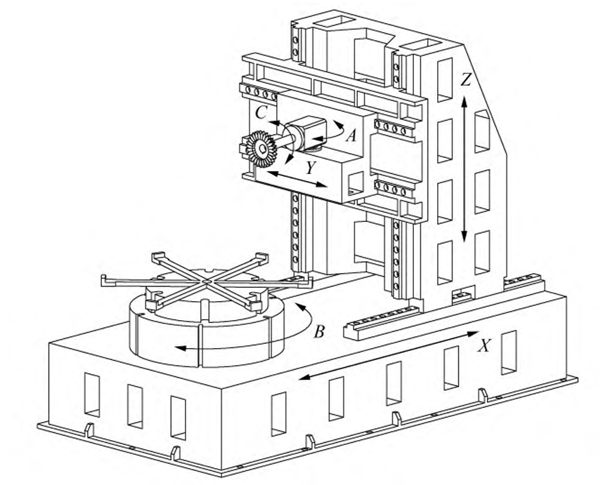
A six-axis CNC skiving machine (Figure 2) was modeled to simulate the process. G-code parameters include axial feed Cz, tool rotation Cc, and face gear rotation CB:Cz=rpv−rp1,CB=i2vφv,i2v=z2zv
Simulated tooth surfaces with varying rake angles (0°, 5°, 10°, 15°) exhibited consistent accuracy, with maximum errors below 10 μm.
5. Conclusion
This study establishes a systematic framework for designing skiving tools tailored to orthogonal spur face gears. By integrating precise involute profile derivation, meshing condition optimization, and numerical validation, the methodology ensures high-precision manufacturing with minimal tooth surface errors. The results underscore the viability of skiving as an efficient and accurate alternative to traditional spur face gear machining methods.