
To calculate the vibration noise of the acoustic boundary element model of helical gear system, it is necessary to obtain the vibration response of the structural model of helical gear system. The response results can be vibration displacement, vibration velocity and vibration acceleration. The meshing force of the helical gear system is calculated, applied to the structural model of the helical gear system, the vibration acceleration of the helical gear surface is calculated, mapped to the acoustic boundary element model of the helical gear system, the acoustic boundary element model of the helical gear system is solved, and the vibration noise of the helical gear system is obtained.
1. Dynamic meshing force of helical gear system
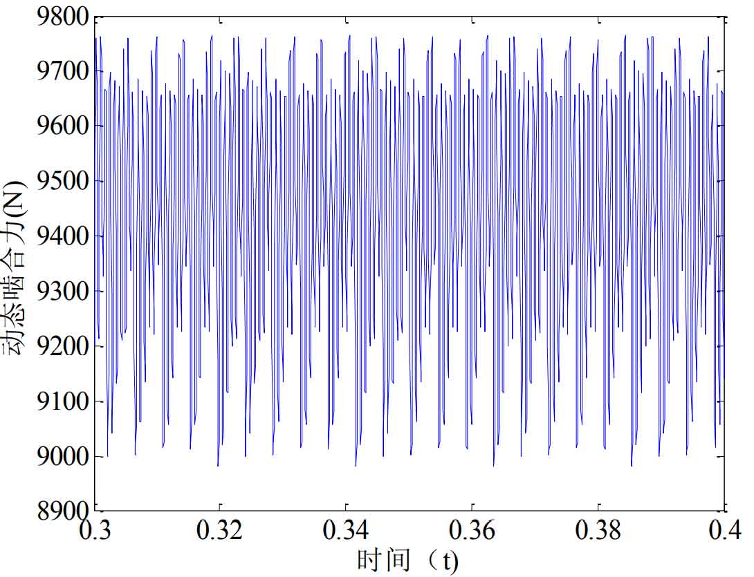
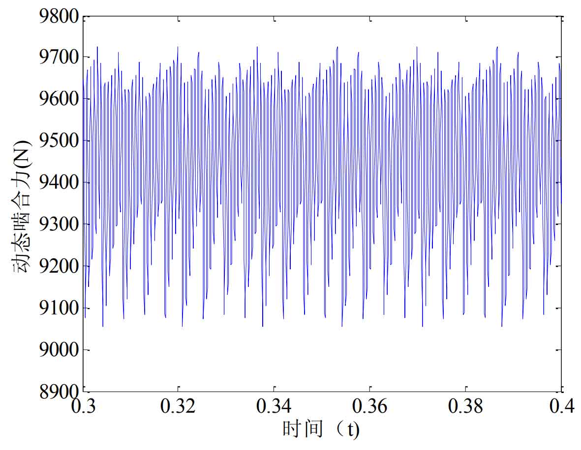
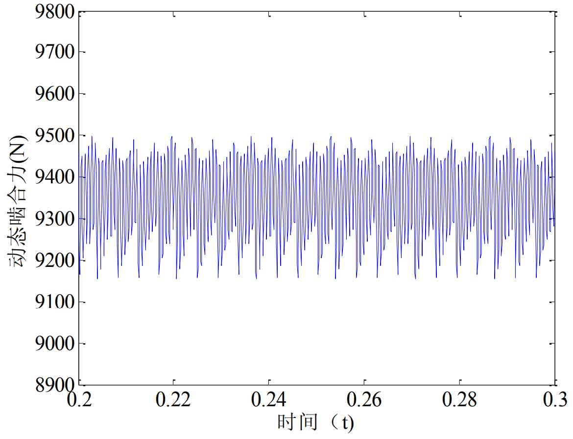
The dynamic meshing force when the friction coefficient is 0.1 before modification is shown in Figure 1. The dynamic meshing force when the friction coefficient is 0.1 after modification is shown in Figure 2. The dynamic meshing force when the friction coefficient is 0.05 after modification is shown in Figure 3. The dynamic meshing force when the friction coefficient is 0 after modification is shown in Figure 4.
2. Boundary conditions of structural vibration response of helical gear system
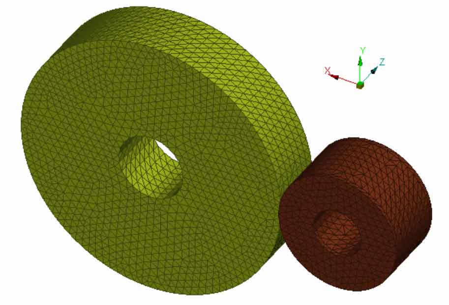
The tangential force, axial force and radial force of driving wheel and driven wheel are obtained from the decomposition of dynamic meshing force of helical gear system, which are applied to the meshing lines of driving wheel and driven wheel respectively. Constrain the translational degrees of freedom and rotational degrees of freedom along the X, y and Z directions at each bearing, as shown in Figure 5.