
In modern aviation and high-performance mechanical systems, spiral bevel gears play a critical role due to their ability to transmit power smoothly and efficiently between intersecting shafts. These gears are prized for their high load-carrying capacity, reduced noise, and operational stability, making them indispensable in applications such as helicopter main reducers, aerospace transmissions, and automotive differentials. However, the theoretical performance of spiral bevel gears is often compromised in real-world operating conditions. Factors like elastic deformations of housings, bearings, shafts, and the gears themselves, combined with assembly errors, manufacturing tolerances, and environmental influences like temperature fluctuations and vibrations, lead to misalignments that disrupt ideal meshing. This misalignment, often referred to as equivalent misalignment, causes the contact pattern on the tooth surface to shift from its designed position and alters the transmission error curve, resulting in increased vibration, noise, and potential premature failure. Therefore, developing an active design methodology that accounts for these real-condition deviations is essential for enhancing the durability and performance of spiral bevel gears. This article delves into a comprehensive approach for identifying equivalent misalignment from actual contact patterns and proactively redesigning the pinion tooth surface to ensure optimal meshing under operational loads.
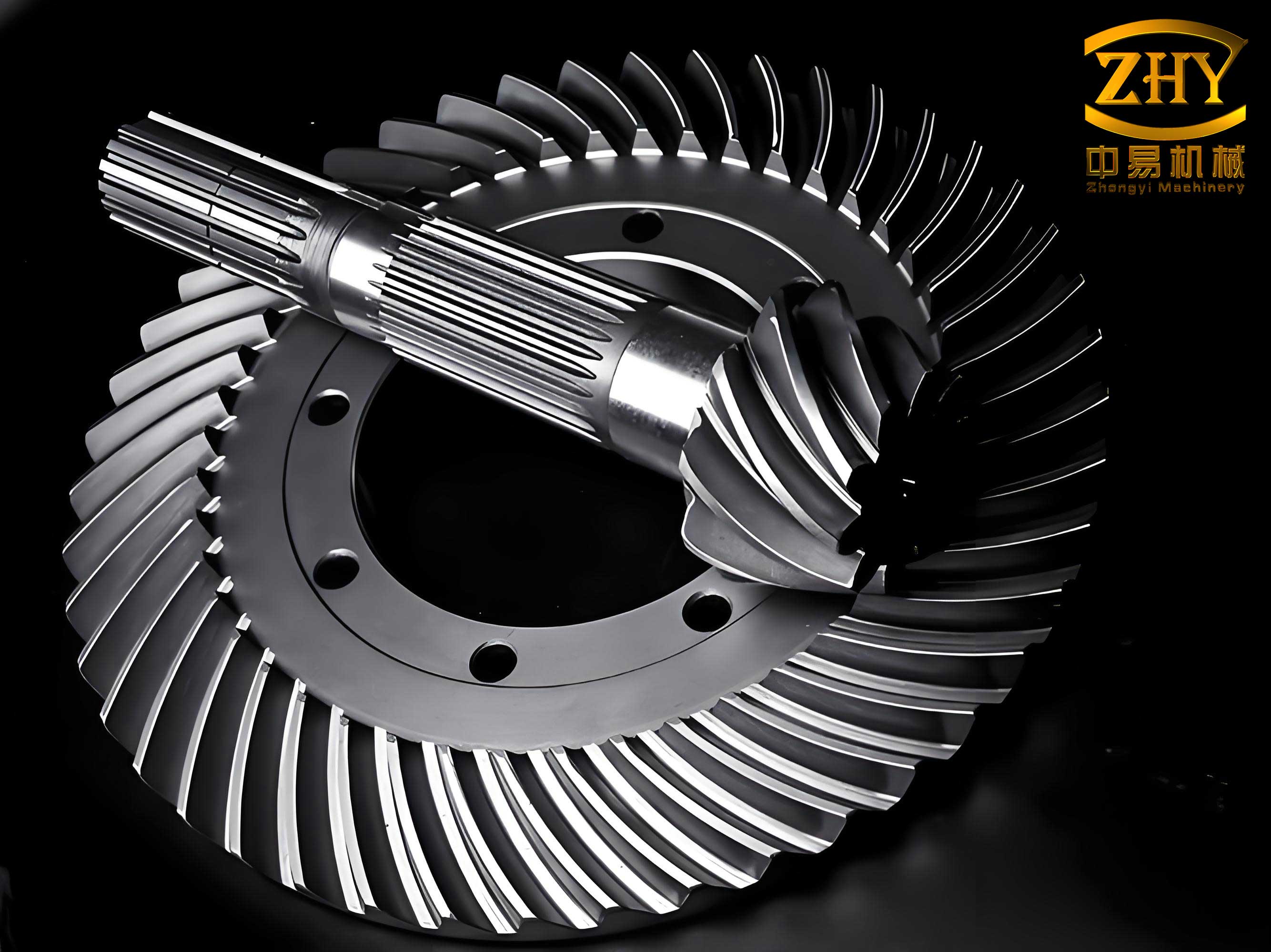
The core challenge in designing spiral bevel gears for actual conditions lies in accurately quantifying the misalignment that occurs during operation. Misalignment in spiral bevel gear pairs can be decomposed into four primary components: pinion axial displacement \(\Delta P\), gear axial displacement \(\Delta G\), offset in the shaft center distance \(\Delta E\), and deviation in the shaft angle \(\Delta \Sigma\). These parameters collectively define the equivalent misalignment vector \(\mathbf{D} = [\Delta P, \Delta G, \Delta E, \Delta \Sigma]^T\). Under ideal assembly, \(\mathbf{D} = \mathbf{0}\), and the gear pair meshes with a predefined contact pattern centered on the tooth flank and a low-amplitude transmission error curve. In practice, however, loads induce deflections, and errors accumulate, leading to a non-zero \(\mathbf{D}\). This misalignment changes the relative position and orientation of the mating tooth surfaces, causing the contact pattern to migrate and potentially become concentrated near the edges of the tooth, which increases contact stress and risk of failure. For spiral bevel gears, the contact pattern—a visible area of contact on the tooth surface after running—is a key indicator of meshing quality. Its location, size, and shape directly influence load distribution, stress levels, and dynamic behavior.
To address this, we first establish a mathematical model for tooth contact analysis (TCA) of spiral bevel gears under misalignment. The tooth surface of a spiral bevel gear, generated via face-milling or face-hobbing processes, can be represented as a vector function \(\mathbf{r}^{(i)}(u, \theta)\), where \(i = p, g\) denotes pinion and gear, respectively, and \(u\) and \(\theta\) are surface parameters. The meshing condition requires that the position vectors and surface normals coincide at the contact point under a prescribed relative motion. For a given misalignment \(\mathbf{D}\), the TCA equations are solved to obtain the contact path and transmission error. The mathematical formulation involves coordinate transformations that incorporate the misalignment parameters. Let \([\mathbf{T}_{mis}(\mathbf{D})]\) be the homogeneous transformation matrix representing the misalignment between the pinion and gear axes. The condition for contact is:
$$\mathbf{r}^{(p)}(u_p, \theta_p) = [\mathbf{T}_{mis}(\mathbf{D})] \cdot \mathbf{r}^{(g)}(u_g, \theta_g)$$
$$\mathbf{n}^{(p)}(u_p, \theta_p) \parallel [\mathbf{R}_{mis}(\mathbf{D})] \cdot \mathbf{n}^{(g)}(u_g, \theta_g)$$
where \(\mathbf{n}\) denotes the unit normal vector, and \([\mathbf{R}_{mis}]\) is the rotational submatrix of \([\mathbf{T}_{mis}]\). Solving these equations yields the contact point coordinates for each roll angle, defining the contact path \(l_d(\mathbf{D})\) on both tooth surfaces. The transmission error \(\Delta \phi(\phi_p)\) is computed as the deviation from the theoretical kinematic relationship.
In actual operation, the contact pattern left on the tooth surfaces after running under load provides direct evidence of the effective misalignment. To utilize this information, we digitize the contact pattern from experimental or simulation data. The pattern is processed to extract its geometric features: the centroid coordinates \((x_c, y_c)\) in a tooth coordinate system, the major and minor axes lengths \(L_{maj}\) and \(L_{min}\), the orientation angle \(\alpha\), and the boundary points. A more precise approach involves extracting the centerline or contact trajectory of the pattern. Suppose we obtain a set of discrete points \(\{\mathbf{p}’_i, i=1,\ldots,n\}\) representing the actual contact path \(l_a\) from the observed pattern. These points are typically obtained via image processing of gear contact test images or from detailed elastohydrodynamic lubrication (EHL) simulations that consider tooth flexibility and load. The digitization process involves converting pixel data into parametric coordinates on the tooth surface.
Given the actual contact path \(l_a\) and a candidate equivalent misalignment vector \(\mathbf{D}\), we can compute the theoretical contact path \(l_d(\mathbf{D})\) via TCA. The goal is to find the \(\mathbf{D}\) that minimizes the deviation between \(l_a\) and \(l_d\). This is formulated as an optimization problem. Let \(\mathbf{p}_i(\mathbf{D})\) be the position vector of the \(i\)-th contact point on \(l_d\) for misalignment \(\mathbf{D}\), and let \(\mathbf{n}_i(\mathbf{D})\) be the corresponding unit normal vector. The deviation at each point can be measured as the normal distance from \(\mathbf{p}’_i\) to the theoretical surface along \(\mathbf{n}_i\). For small deviations, this distance \(h_i\) is approximated as:
$$h_i(\mathbf{D}) = (\mathbf{p}’_i – \mathbf{p}_i(\mathbf{D})) \cdot \mathbf{n}_i(\mathbf{D})$$
The overall deviation vector for a gear surface is \(\mathbf{h}(\mathbf{D}) = [h_1, h_2, \ldots, h_n]^T\). For both pinion and gear surfaces, and considering multiple load conditions (e.g., light load and heavy load), we construct a multi-objective optimization problem. Suppose we have \(K\) load conditions (e.g., \(K=2\)). For each load condition \(k\), we have actual contact paths \(l_{a,k}^{(p)}\) and \(l_{a,k}^{(g)}\) for pinion and gear, respectively. The optimization aims to minimize the weighted sum of squared deviations:
$$\min f^{(p)}(\mathbf{D}) = \sum_{k=1}^{K} w_k \left[ \mathbf{h}_{k}^{(p)}(\mathbf{D}) \right]^T \mathbf{h}_{k}^{(p)}(\mathbf{D})$$
$$\min f^{(g)}(\mathbf{D}) = \sum_{k=1}^{K} w_k \left[ \mathbf{h}_{k}^{(g)}(\mathbf{D}) \right]^T \mathbf{h}_{k}^{(g)}(\mathbf{D})$$
$$\text{subject to } \mathbf{D}_{lb} \leq \mathbf{D} \leq \mathbf{D}_{ub}$$
where \(w_k\) are weight coefficients reflecting the importance of each load condition (e.g., \(w_1=0.8\) for 70% load, \(w_2=0.2\) for 140% load), and \(\mathbf{D}_{lb}\), \(\mathbf{D}_{ub}\) are practical bounds on misalignment parameters. This multi-objective problem can be solved using advanced algorithms like NSGA-II (Non-dominated Sorting Genetic Algorithm II), which yields a Pareto front of solutions balancing pinion and gear deviations. In practice, a single solution can be selected based on engineering judgment, such as prioritizing pinion contact or minimizing maximum deviation.
Once the equivalent misalignment \(\mathbf{D}^*\) is identified, the next step is to actively redesign the pinion tooth surface so that under this misalignment, the gear pair exhibits a favorable contact pattern and transmission error similar to the ideal condition. This is achieved by modifying the pinion machining parameters in the gear generation process. The local synthesis method is employed, which allows for controlled modification of tooth geometry by adjusting machine tool settings. For spiral bevel gears generated on face-milling machines (e.g., Gleason method), key parameters include cutter radius \(R_c\), blade angle \(\alpha_c\), radial distance \(S_r\), angular position \(q\), machine root angle \(\gamma_m\), and modified roll coefficients \(a, b, c\) for higher-order corrections. The goal is to find a new set of pinion machine settings \(\mathbf{X}_{p,new}\) such that when the gear is meshed with the existing gear surface under misalignment \(\mathbf{D}^*\), the contact conditions meet targets: desired contact path location, transmission error amplitude, and low sensitivity to misalignment variations.
The local synthesis equations are derived from the meshing condition and require specifying at a chosen reference point (usually the mid-point of the tooth): the contact point position, the tangent vector of the contact path, and the second-order properties related to the transmission error curve. By imposing that under misalignment \(\mathbf{D}^*\) the contact path passes through a target point and has a desired direction, we can solve for the required pinion surface curvature. The mathematical formulation involves the relative curvature between the surfaces. Let \(\kappa_{rel}\) be the relative normal curvature along the contact path direction. To achieve a parabolic function of transmission error (which is beneficial for noise reduction), we require \(\kappa_{rel}\) to vary linearly along the path. The local synthesis equations are:
$$\mathbf{r}^{(p)}_{new} = \mathbf{r}^{(g)} \quad \text{(position congruence)}$$
$$\mathbf{n}^{(p)}_{new} \parallel \mathbf{n}^{(g)} \quad \text{(normal alignment)}$$
$$\frac{\partial \kappa_{rel}}{\partial s} = C \quad \text{(controlled curvature variation)}$$
where \(s\) is the arc length along the contact path, and \(C\) is a constant determining the transmission error parabola length. These conditions, combined with the machine kinematics, yield a system of nonlinear equations that can be solved for the new pinion machine settings \(\mathbf{X}_{p,new}\). Computational tools or iterative algorithms are used to obtain the solution.
To illustrate the entire methodology, consider a detailed example of an aviation spiral bevel gear pair. The basic geometric parameters are listed in Table 1.
| Parameter | Pinion | Gear |
|---|---|---|
| Number of teeth | 23 | 65 |
| Module (mm) | 3.9 | |
| Mid-spiral angle (°) | 30 | |
| Hand of spiral | Right-hand | Left-hand |
| Shaft angle (°) | 90 | |
| Face width (mm) | 37 | |
The gear is assumed to be generated with fixed machine settings. The initial pinion concave side machining parameters are given in Table 2.
| Machine Setting Parameter | Initial Value (Pinion Concave) |
|---|---|
| Cutter radius \(R_c\) (mm) | 92.8549 |
| Blade angle \(\alpha_c\) (°) | 22.5 |
| Radial distance \(S_r\) (mm) | 100.1300 |
| Angular position \(q\) (°) | 49.3364 |
| Machine roll ratio \(R_{roll}\) | 2.8218 |
| Vertical offset \(V\) (mm) | 5.27776 |
| Axial offset \(H\) (mm) | -2.1755 |
| Blank offset \(B\) (mm) | 0.4941 |
| Machine root angle \(\gamma_m\) (°) | 18.6165 |
| Second-order modified roll coefficient \(a\) | -0.0587 |
| Third-order modified roll coefficient \(b\) | 0.1705 |
Performing TCA under ideal alignment (\(\mathbf{D}=\mathbf{0}\)) yields the contact pattern and transmission error shown in Figure 1 (simulated). The contact pattern is centrally located, and the transmission error curve has a low amplitude parabolic shape.
Now, suppose we have actual operation data from two load conditions: 70% of rated torque and 140% of rated torque. The observed contact patterns on the pinion are digitized to obtain the actual contact paths \(l_{a,1}^{(p)}\) and \(l_{a,2}^{(p)}\). For the 70% load, the pattern might be slightly shifted toward the toe, and for the 140% load, it shifts further and perhaps toward the heel. The digitized data points are used in the optimization. Applying the NSGA-II algorithm with bounds on misalignment: \(-1.0 \leq \Delta P \leq 1.0\) mm, \(-1.0 \leq \Delta G \leq 1.0\) mm, \(-0.5 \leq \Delta E \leq 0.5\) mm, \(-0.5 \leq \Delta \Sigma \leq 0.5\)°, and weights \(w_1=0.8\), \(w_2=0.2\), we obtain the optimal equivalent misalignment vector \(\mathbf{D}^*\) as in Table 3.
| Misalignment Component | Identified Value |
|---|---|
| Gear axial displacement \(\Delta G\) (mm) | -0.1000 |
| Pinion axial displacement \(\Delta P\) (mm) | -0.9106 |
| Shaft center distance offset \(\Delta E\) (mm) | -0.4531 |
| Shaft angle deviation \(\Delta \Sigma\) (°) | 0.5000 |
With \(\mathbf{D}^*\) known, we proceed to redesign the pinion tooth surface. Using local synthesis, we target a contact pattern centered on the tooth under misalignment \(\mathbf{D}^*\) and a parabolic transmission error with amplitude similar to the ideal. Solving the local synthesis equations yields a new set of pinion machining parameters, as shown in Table 4.
| Machine Setting Parameter | Redesigned Value (Pinion Concave) |
|---|---|
| Cutter radius \(R_c\) (mm) | 92.1093 |
| Blade angle \(\alpha_c\) (°) | 22.5 |
| Radial distance \(S_r\) (mm) | 96.8092 |
| Angular position \(q\) (°) | 49.1357 |
| Machine roll ratio \(R_{roll}\) | 2.7348 |
| Vertical offset \(V\) (mm) | 7.0000 |
| Axial offset \(H\) (mm) | -4.5093 |
| Blank offset \(B\) (mm) | 1.2392 |
| Machine root angle \(\gamma_m\) (° | 18.5967 |
| Second-order modified roll coefficient \(a\) | -0.0656 |
| Third-order modified roll coefficient \(b\) | 0.5061 |
To verify the redesign, TCA is performed for the new pinion with the original gear under the identified equivalent misalignment \(\mathbf{D}^*\). The results show that the contact pattern is now repositioned near the center of the tooth, and the transmission error curve regains its parabolic shape with low amplitude. This demonstrates the effectiveness of the active design approach. The process not only compensates for the misalignment but also can improve the gear pair’s tolerance to future variations. For spiral bevel gears, such proactive design is crucial for achieving reliable performance in demanding aviation environments.
The mathematical robustness of the method can be further enhanced by incorporating stochastic models for errors and loads. Since actual misalignments have random components, a probabilistic framework can be used. Suppose the misalignment vector \(\mathbf{D}\) is treated as a random variable with mean \(\boldsymbol{\mu}_D\) and covariance matrix \(\boldsymbol{\Sigma}_D\). The optimization can then aim to minimize the expected deviation over the distribution. For instance, the objective function becomes:
$$\min E\left[ \sum_{k} w_k \| \mathbf{h}_k(\mathbf{D}) \|^2 \right]$$
where the expectation is taken over \(\mathbf{D}\). This leads to a robust optimization problem that yields a design less sensitive to random variations. Additionally, the tooth contact analysis can be extended to include thermo-elastic effects. Under load, tooth surfaces experience temperature rises due to friction, which changes material properties and induces thermal distortions. The tooth surface equation can be modified to include a thermal displacement field \(\mathbf{u}_{th}(T)\). The contact condition then becomes:
$$\mathbf{r}^{(p)} + \mathbf{u}_{th}^{(p)} = [\mathbf{T}_{mis}] \cdot (\mathbf{r}^{(g)} + \mathbf{u}_{th}^{(g)})$$
This complicates the analysis but provides a more accurate representation of actual operating conditions for spiral bevel gears.
Another important aspect is the computational efficiency of the optimization. Solving TCA for each candidate \(\mathbf{D}\) in an iterative optimization loop can be time-consuming, especially for high-fidelity models. To accelerate the process, surrogate modeling techniques like Kriging or polynomial chaos expansion can be employed. A surrogate model \(\tilde{\mathbf{h}}(\mathbf{D})\) approximates the deviation function based on a limited set of high-fidelity TCA evaluations. The optimization then uses the surrogate, which is computationally cheap, to explore the design space. Once an optimum is found, it can be validated with a full TCA. This approach is particularly useful when dealing with multiple load cases and complex gear geometries.
Furthermore, the active design methodology can be integrated into a digital twin framework for spiral bevel gears. A digital twin continuously updates the misalignment estimate based on real-time sensor data (e.g., vibration, temperature, torque) from the gearbox. The identified misalignment can then be used to dynamically adjust the design parameters for future manufacturing or to recommend operational adjustments. This closes the loop between design, manufacturing, and operation, leading to smarter and more adaptive gear systems.
In summary, the active design of spiral bevel gears based on actual operating conditions involves a systematic process: digitizing actual contact patterns, identifying equivalent misalignment through multi-objective optimization, and redesigning the pinion tooth surface via local synthesis. This approach ensures that spiral bevel gears perform optimally under real-world loads and misalignments, enhancing durability and reducing noise and vibration. The use of advanced optimization algorithms and probabilistic considerations further refines the method. For aviation applications, where reliability is paramount, such proactive design strategies are invaluable. Future work may focus on integrating real-time data and machine learning to further automate and improve the accuracy of misalignment identification and design adaptation for spiral bevel gears.
To conclude, spiral bevel gears are complex components whose performance is highly sensitive to misalignments. By actively designing the tooth surface to account for identified equivalent misalignment, engineers can significantly improve meshing quality under actual conditions. The methodology presented here, combining TCA, optimization, and local synthesis, provides a robust framework for achieving this goal. As computational power increases and sensor technologies advance, such approaches will become standard practice in the design of high-performance spiral bevel gears for aviation and other critical industries.