With the development of computer technology, the method of using virtual machining technology to create gear geometric model has been paid attention to and widely used. This method has high modeling accuracy and has increasingly become a common gear modeling method. The shape of spiral bevel gear tooth surface is complex, the adjustment parameters of machining machine tool are many, and the machining principle is cumbersome. The tooth profile can not be described by a unified analytical expression, so it is difficult to directly construct the tooth profile surface and transition surface through the analytical equation. The processing principle of spiral bevel gear determines its tooth system. Gleason spiral bevel gear and Oerlikon spiral bevel gear are the two most widely used tooth systems. Spiral bevel gears with different tooth systems correspond to different machining principles and machining machines. Although there are many kinds of spiral bevel gear processing machines with the same tooth system, their design principles are basically the same. Gleason spiral bevel gear, which is most used in China, is taken as the research object.
The design principle of spiral bevel gear machine tool machining gear is that there is an imaginary flat top gear concentric with the angle of the machine tool shaking table. The rotation of the machine tool shaking table makes the imaginary gear form meshing motion with the machined workpiece. The milling cutter head blade is installed on the shaking table of the machine tool, and the movement track surface formed in the process of cutting the workpiece replaces the tooth surface of the imaginary flat top gear. When the workpiece rotates with the imaginary gear according to a certain speed ratio, the milling cutter head will cut the tooth groove surface of spiral bevel gear on the surface of the machined tooth blank. The cutting process of spiral bevel gear is like the meshing transmission process of a pair of spiral bevel gears. It is assumed that the surface of flat top gear and gear blank is a pair of meshing surfaces. Determining the pitch parameters of the hypothetical flat top gear and determining its relative position and motion relationship with the gear blank is an important work in machining spiral bevel gear, so as to ensure that the processed spiral bevel gear and large and small gears can mesh correctly. In this method, the tooth surface of spiral bevel gear is processed by generating method, and the tooth root surface of gear is also processed.
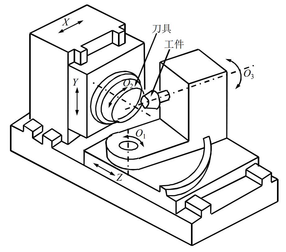
The figure is the structural diagram of a CNC spiral bevel gear grinding machine. This machine tool has six degrees of freedom: three linear motions (x, y, z) and three rotary motions (O1, O2, O3). One of the degrees of freedom is to control the rotation of the tool, which has nothing to do with the formation process of the tooth surface. There are only five degrees of freedom controlling the relative motion relationship between the tool and the workpiece, and the variation of these five degrees of freedom is determined by the adjustment parameters of the machine tool.

