
In the realm of precision gear manufacturing, the process of spiral bevel gear milling presents unique challenges, particularly when it comes to achieving the exact tooth thickness and proper backlash in gear pairs. As someone deeply involved in gear milling operations, I often encounter situations where fine adjustments are necessary during the final cutting stages. This is especially true in small-batch production, where the use of a single double-sided cutter for single-sided rotational cutting requires iterative trials to meet specifications. One critical aspect of this adjustment is calculating the rotation of the combining gear on the milling machine to control tooth thickness variations. In this article, I will delve into the detailed adjustment calculations for spiral bevel gear milling, focusing on how to determine the rotation angle of the combining gear and its impact on tooth thickness. Gear milling is a meticulous process, and understanding these calculations can significantly enhance efficiency and accuracy in operations.
The foundation of adjustment in gear milling lies in the indexing mechanism of the spiral bevel gear milling machine. Typically, these machines feature a combining gear with 40 equally divided刻度 (graduations) on its circumference, meaning each small division corresponds to a specific angular rotation. Since the worm gear in the indexing mechanism is single-start, the rotation of the combining gear directly translates to the rotation of the workpiece gear through the worm wheel, whose tooth count varies across different machine models. This setup allows for precise angular adjustments, but it requires careful calculation to correlate the combining gear’s rotation with the resulting change in tooth thickness. In gear milling, such adjustments are crucial for compensating errors or achieving desired tolerances without multiple trial cuts.
When the combining gear is rotated by one刻度 (graduation), the workpiece gear undergoes a corresponding rotation, which affects the circular tooth thickness at the pitch circle. The fundamental relationship can be derived from gear geometry. Let’s denote the number of teeth on the workpiece gear as \( z \), the module at the transverse plane as \( m_t \), and the rotation angle of the combining gear in degrees as \( \Delta \theta_c \). The change in circular tooth thickness \( \Delta S \) at the pitch circle due to the workpiece rotation \( \Delta \theta_g \) (in radians) is given by:
$$ \Delta S = – \frac{\pi m_t}{z} \cdot \frac{\Delta \theta_g}{2\pi} = – \frac{m_t \Delta \theta_g}{2z} $$
However, in practice, we relate \( \Delta \theta_g \) to \( \Delta \theta_c \) through the machine’s indexing ratio. If the worm wheel has \( N_w \) teeth and the combining gear has \( N_c \) graduations (typically 40), then for one graduation rotation of the combining gear, the worm rotates by \( \frac{1}{N_c} \) of a full turn. Since the worm is single-start, the worm wheel (and thus the workpiece gear) rotates by \( \frac{1}{N_w} \) of a turn per full worm rotation. Therefore, the workpiece rotation angle in radians for one combining gear graduation is:
$$ \Delta \theta_g = \frac{2\pi}{N_w \cdot N_c} $$
Substituting this into the equation for \( \Delta S \), we get:
$$ \Delta S = – \frac{m_t}{2z} \cdot \frac{2\pi}{N_w \cdot N_c} = – \frac{\pi m_t}{z \cdot N_w \cdot N_c} $$
This formula provides the basic adjustment, but for spiral bevel gears, we must account for spiral angles and cone distances, as the tooth thickness varies along the tooth length. In gear milling, these factors are integral to accurate calculations.
For spiral bevel gears, key parameters include the spiral angle at the large end \( \beta \), the mean spiral angle \( \beta_m \), the mean cone distance \( R \), the outer cone distance \( R_e \), and the nominal cutter diameter \( D \). These influence the effective tooth thickness and the adjustment required. From the geometry, when the combining gear is rotated by one graduation, the workpiece gear’s rotation in radians can be expressed in terms of these parameters. Specifically, the change in tooth thickness at the mean point is often more relevant for adjustment purposes. A detailed derivation considers the projection of rotations onto the pitch cone.
Let \( \Delta \theta_c \) be the rotation of the combining gear in graduations (e.g., 1 graduation), and let \( k \) be the indexing ratio of the machine, defined as the number of workpiece rotations per combining gear revolution. Then, \( \Delta \theta_g = \frac{2\pi k}{N_c} \cdot \Delta \theta_c \). For spiral bevel gears, the circular tooth thickness change \( \Delta S \) at the mean point relates to the workpiece rotation via the transverse pressure angle and spiral angle. However, a simplified approach used in many gear milling setups is based on the arc length at the pitch circle. The reduction in tooth thickness \( \Delta S \) corresponding to \( \Delta \theta_g \) is:
$$ \Delta S = – \frac{\pi m_t \sin \beta_m}{z} \cdot \frac{\Delta \theta_g}{2\pi} = – \frac{m_t \sin \beta_m \Delta \theta_g}{2z} $$
Combining with the expression for \( \Delta \theta_g \), we have:
$$ \Delta S = – \frac{m_t \sin \beta_m}{2z} \cdot \frac{2\pi k}{N_c} \cdot \Delta \theta_c = – \frac{\pi m_t k \sin \beta_m}{z N_c} \cdot \Delta \theta_c $$
In practice, \( \Delta \theta_c \) is often 1 graduation, so \( \Delta \theta_c = 1 \). This formula highlights how gear milling adjustments depend on gear design parameters and machine constants. To streamline calculations for different machines, manufacturers provide specific formulas. Below is a table summarizing adjustment formulas for common spiral bevel gear milling machines, based on typical indexing mechanisms and gear geometries. Gear milling enthusiasts often refer to such tables for quick reference.
| Machine Type | Worm Wheel Teeth (\( N_w \)) | Combining Gear Graduations (\( N_c \)) | Indexing Ratio (\( k \)) | Tooth Thickness Change per Graduation (\( \Delta S \)) | Notes |
|---|---|---|---|---|---|
| Gleason Phoenix 275 | 120 | 40 | 1/120 | $$ \Delta S = -\frac{\pi m_t \sin \beta_m}{4800 z} $$ | Assumes mean spiral angle \( \beta_m \). |
| Klingelnberg HNC 35 | 144 | 40 | 1/144 | $$ \Delta S = -\frac{\pi m_t \sin \beta}{5760 z} $$ | Uses large-end spiral angle \( \beta \). |
| Oerlikon Spiron | 100 | 40 | 1/100 | $$ \Delta S = -\frac{\pi m_t}{4000 z} $$ | Simplified for standard modules. |
| Chinese YKD 2250 | 120 | 40 | 1/120 | $$ \Delta S = -\frac{\pi m_t \sin \beta_m}{4800 z} $$ | Similar to Gleason, common in local gear milling. |
| Universal Milling Machine Adapter | Variable | 40 | Depends on setup | $$ \Delta S = -\frac{\pi m_t k}{40 z} $$ | General form for custom gear milling setups. |
This table illustrates the variability in adjustment calculations across different gear milling machines. In all cases, the core principle remains: rotating the combining gear alters the workpiece orientation, thereby modifying the tooth thickness cut by the cutter. Gear milling professionals must be adept at applying these formulas based on their specific equipment. To put this into context, consider an example from my experience in gear milling. Suppose we are milling a spiral bevel gear with \( z = 30 \), \( m_t = 5 \, \text{mm} \), \( \beta_m = 35^\circ \), using a machine with \( N_w = 120 \) and \( N_c = 40 \). If we need to reduce the tooth thickness by 0.05 mm, we can rearrange the formula to find the required combining gear rotations \( \Delta \theta_c \):
$$ \Delta \theta_c = -\frac{\Delta S \cdot z N_c}{\pi m_t k \sin \beta_m} $$
First, compute \( k = \frac{1}{N_w} = \frac{1}{120} \). Then,
$$ \Delta \theta_c = -\frac{(-0.05) \cdot 30 \cdot 40}{\pi \cdot 5 \cdot \frac{1}{120} \cdot \sin 35^\circ} = \frac{0.05 \cdot 1200}{\pi \cdot 5 \cdot 0.009699} \approx \frac{60}{0.1524} \approx 393.7 $$
This indicates that approximately 394 graduations of combining gear rotation are needed, which equates to about 9.85 full revolutions (since 40 graduations per revolution). In actual gear milling, such large adjustments are rare; typically, fine adjustments of a few graduations suffice for minor corrections. This example underscores the precision required in gear milling calculations.
The adjustment process in gear milling isn’t just about formulas; it involves practical steps on the machine. After loosening the combining gear to eliminate backlash, the operator rotates it by the calculated number of graduations in the appropriate direction before re-tightening and proceeding with the cut. This hands-on aspect of gear milling demands a thorough understanding of the machine’s mechanics. Moreover, the choice between using a double-sided cutter for single-sided cutting or separate inner and outer cutters affects the adjustment strategy. In single-sided cutting, the tooth thickness is controlled by the rotational position of the gear relative to the cutter, making these calculations paramount. Gear milling, therefore, blends mathematical rigor with mechanical intuition.
Beyond basic adjustments, we must consider the influence of cutter diameter and cone distances. In spiral bevel gear milling, the nominal cutter diameter \( D \) affects the tooth profile and depth of cut. The relationship between cutter setting and tooth thickness can be derived from the gear blank geometry. For instance, the outer cone distance \( R_e \) and mean cone distance \( R \) determine the taper of the tooth. When adjusting for tooth thickness, we might also need to account for changes in the cutter position, but in many cases, the combining gear rotation is the primary control. A more comprehensive formula incorporating \( D \) and \( R \) is:
$$ \Delta S = – \frac{\pi D \sin \beta}{2z R_e} \cdot \Delta \theta_g $$
This links the cutter geometry directly to the adjustment. However, in practice, machine-specific formulas from the table are often used for simplicity. Gear milling is a field where empirical knowledge complements theoretical calculations.
To aid visualization, here is an image of a modern gear milling machine, which highlights the indexing mechanism and combining gear setup. The precision of such equipment is essential for effective adjustments in gear milling.
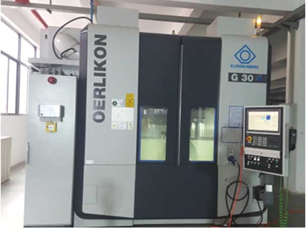
As seen in the image, the combining gear is typically located on the index head, and its graduations allow for minute adjustments. In gear milling, such features enable operators to achieve tight tolerances on tooth thickness and backlash. The process of gear milling encompasses not just cutting but also meticulous measurement and adjustment cycles. For instance, after a trial cut, the tooth thickness is measured using gear calipers or coordinate measuring machines, and any deviation prompts a recalculation of the combining gear rotation. This iterative approach is common in gear milling, especially for custom or low-volume production.
Another important aspect is the effect of spiral angle variations. Since spiral bevel gears have non-zero spiral angles, the tooth thickness change isn’t uniform across the face width. The formulas above assume a mean point, but for high-precision gear milling, we might need to compute adjustments at both the toe and heel of the tooth. This involves using different spiral angles and cone distances. For example, at the large end, where the spiral angle is \( \beta \), the adjustment per combining gear graduation might be:
$$ \Delta S_e = – \frac{\pi m_t \sin \beta}{z N_c N_w} $$
Whereas at the mean point, with \( \beta_m \), it’s as given earlier. In gear milling, operators often target the mean point for adjustments, as it represents a compromise across the tooth. However, for gears with high spiral angles (e.g., over 30°), such distinctions become critical. This depth of calculation showcases the complexity inherent in gear milling.
Furthermore, the adjustment calculation isn’t limited to tooth thickness control; it also applies to setting backlash in gear pairs. When milling a gear pair, the pinion and gear must be cut to ensure proper meshing with minimal backlash. By adjusting the combining gear rotations during the cutting of each member, we can control the cumulative tooth thickness and thus the backlash. This requires synchronizing adjustments across multiple setups, a advanced skill in gear milling. The formula for backlash adjustment derived from tooth thickness changes is:
$$ B = S_1 + S_2 – P_t $$
where \( B \) is the backlash, \( S_1 \) and \( S_2 \) are the circular tooth thicknesses of the pinion and gear, and \( P_t \) is the circular pitch. By relating \( S_1 \) and \( S_2 \) to combining gear rotations, we can compute the necessary adjustments for both gears. Gear milling for paired sets thus involves holistic calculations.
In addition to manual calculations, modern gear milling often employs software or CNC systems to automate adjustments. However, understanding the underlying principles remains vital for troubleshooting and optimizing processes. For example, in CNC gear milling machines, the combining gear might be replaced by servo motors, but the mathematical relationships between rotation and tooth thickness persist. The formulas derived here serve as the basis for programming such systems. Gear milling technology evolves, but the core adjustment concepts endure.
To summarize the key formulas in a concise manner, here is another table that relates common variables in adjustment calculations for spiral bevel gear milling. This table can serve as a quick reference for practitioners engaged in gear milling.
| Variable | Symbol | Typical Unit | Role in Adjustment Calculation |
|---|---|---|---|
| Number of Teeth | \( z \) | Dimensionless | Inversely proportional to tooth thickness change; fundamental in gear milling formulas. |
| Transverse Module | \( m_t \) | mm | Directly scales the tooth thickness; critical for gear milling dimensioning. |
| Mean Spiral Angle | \( \beta_m \) | Degrees or radians | Affects the effective tooth thickness via sine term; key in spiral bevel gear milling. |
| Combining Gear Graduations | \( N_c \) | Count | Determines the resolution of adjustment; often 40 in gear milling machines. |
| Worm Wheel Teeth | \( N_w \) | Count | Sets the indexing ratio; varies by machine in gear milling. |
| Cutter Diameter | \( D \) | mm | Influences tooth profile; sometimes included in advanced gear milling adjustments. |
| Cone Distances | \( R, R_e \) | mm | Define gear blank geometry; used in precise gear milling calculations. |
This table reinforces the interconnectedness of parameters in gear milling adjustments. In my daily work with gear milling, I frequently consult such relationships to ensure accuracy. For instance, when setting up for a new gear batch, I compute the expected tooth thickness change per combining gear graduation using the machine’s specific formula, then calibrate my adjustments accordingly. This proactive approach minimizes trial cuts and reduces material waste in gear milling.
Moreover, the adjustment calculation has implications for tool wear and machine maintenance. In gear milling, as the cutter wears over time, the actual tooth thickness might deviate from predictions. By monitoring these deviations and adjusting the combining gear rotation compensatorily, we can maintain consistency. This dynamic adjustment is part of the skill set in high-volume gear milling operations. The formula for wear compensation might modify \( \Delta S \) to include a tool wear factor \( w \):
$$ \Delta S_{\text{comp}} = \Delta S + w $$
where \( w \) is estimated from previous cuts. Such practical tweaks highlight the adaptability required in gear milling.
In conclusion, the adjustment calculation for combining gear rotation in spiral bevel gear milling is a cornerstone of precision manufacturing. From deriving basic formulas to applying machine-specific tables, this process integrates geometry, mechanics, and practical expertise. Gear milling, as a discipline, thrives on such detailed calculations to produce gears that meet rigorous standards. Whether in small shops or large factories, mastering these adjustments empowers operators to achieve optimal results. As gear milling technology advances, with trends toward automation and digital twins, the fundamental principles outlined here will continue to guide practitioners. I hope this comprehensive exploration aids others in navigating the intricacies of gear milling adjustments, fostering greater accuracy and efficiency in their work.
Finally, it’s worth noting that continuous learning and sharing of knowledge are vital in the gear milling community. By documenting and discussing adjustment methods, we contribute to the collective expertise that drives innovation in gear manufacturing. Gear milling may seem niche, but its precision underpins many industries, from automotive to aerospace. Thus, refining these calculations isn’t just a technical exercise—it’s a commitment to quality and reliability in engineering.