
The pursuit of operational excellence in complex mechanical systems hinges on the reliable performance of their core components. Among these, the spiral bevel gear stands out for its critical role in transmitting power between non-parallel, intersecting shafts. Renowned for high load capacity, smooth engagement, and superior durability, the spiral bevel gear is a cornerstone in automotive differentials, aviation transmissions, and heavy industrial machinery. Its performance directly influences system efficiency, noise levels, and operational lifespan. The meshing quality, often qualitatively assessed through visual inspection of contact patterns (or “bearing marks”) on the tooth flanks, is a primary indicator of a spiral bevel gear’s health and assembly accuracy. Traditional assessment relies heavily on the skilled eye of an engineer, making the process subjective, time-consuming, and inconsistently reproducible. This creates a significant need for an objective, quantifiable, and efficient method to evaluate transmission precision.
This article proposes a novel, data-driven framework that utilizes acoustic emission analysis as an auxiliary tool for detecting the transmission precision of spiral bevel gears. The core hypothesis is that deviations from ideal meshing conditions, such as those induced by assembly errors, manifest as distinct, measurable signatures in the sound spectrum generated during operation. By capturing and intelligently processing these acoustic signals, we can correlate specific acoustic features with the quality of the tooth contact pattern and, by extension, the gear’s传动精度 (transmission accuracy). We integrate an optimized signal processing chain, centered on Maximum Correlated Kurtosis Deconvolution (MCKD) tuned by a Particle Swarm Optimization (PSO) algorithm, to extract weak, periodic impulse features from noisy sound signals. This PSO-MCKD method enables the precise monitoring of meshing frequency harmonics, whose amplitudes serve as our primary quantitative metrics for assessing spiral bevel gear performance.
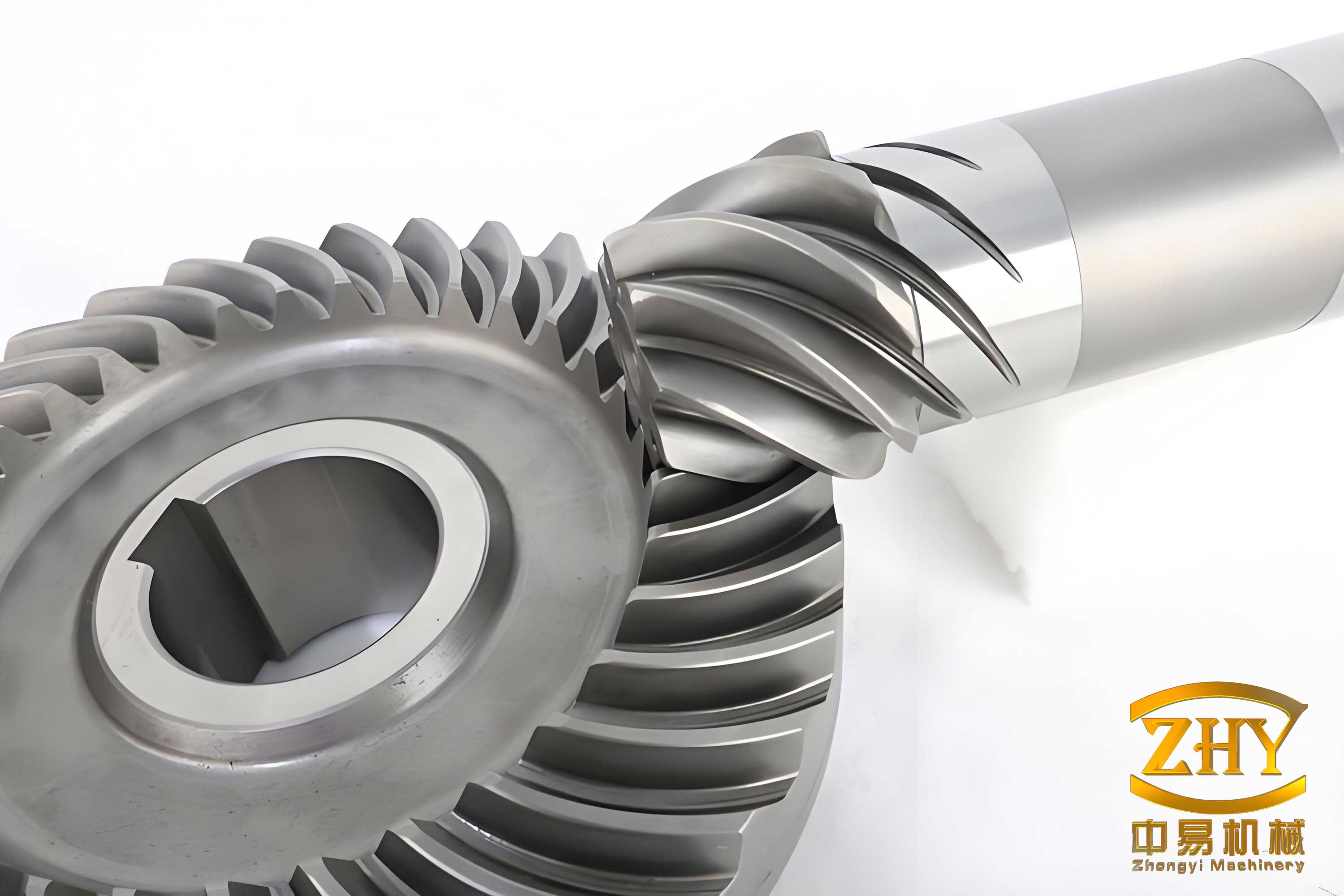
The operational excellence of a spiral bevel gear pair is fundamentally governed by the characteristics of the contact pattern formed between their mating teeth. An ideal pattern is typically elliptical, located centrally on the tooth flank, and has an appropriate size. This ensures even load distribution, minimizes stress concentrations, and promotes smooth, quiet operation. However, real-world installation is never perfect. The most common and impactful assembly error is axial misalignment, defined as the deviation of a gear from its theoretically optimal axial mounting position. We denote the axial deviation of the pinion (smaller gear) as $\Delta T$ and of the gear (larger wheel) as $\Delta G$.
Even minor axial deviations can drastically alter the contact pattern. A positive $\Delta T$ (pinion moved further into mesh) often shifts the pattern towards the toe (thin end) and heel (thick end) of the pinion tooth, potentially causing edge loading. Conversely, a negative $\Delta T$ (pinion withdrawn) shifts the pattern towards the pinion’s toe and the gear’s heel. These shifts change the effective contact area and pressure distribution, leading to increased vibration, elevated operating noise, accelerated wear, and reduced fatigue life. Therefore, detecting and quantifying the effects of axial misalignment is synonymous with assessing the foundational传动精度 (transmission accuracy) of the spiral bevel gear pair.
The sound produced by a meshing spiral bevel gear pair is a rich information carrier. It is the airborne representation of the structural vibrations resulting from the dynamic tooth contact forces. Under ideal conditions, the sound spectrum is dominated by the fundamental meshing frequency ($f_m$) and its harmonics ($2f_m$, $3f_m$, etc.), with relatively low amplitude. When misalignment or other faults occur, the tooth engagement becomes impacted. The impact events generate broad-band excitations that modulate the regular meshing vibration, leading to an increase in the amplitude of the meshing frequency and its harmonics in the acoustic spectrum. Furthermore, sidebands often appear around these frequencies. Thus, monitoring the acoustic spectrum, specifically the amplitudes at $f_m$, $2f_m$, and $3f_m$, provides a direct, non-intrusive window into the meshing dynamics and health of the spiral bevel gear.
The PSO-MCKD Signal Processing Framework
The primary challenge in acoustic-based monitoring is the low signal-to-noise ratio (SNR). The impact signals indicative of faulty meshing are often weak and buried in strong background noise from motors, other machine elements, and the environment. Traditional Fourier analysis may fail to reveal these features. This is where advanced signal processing is critical. Our proposed method combines the strengths of Maximum Correlated Kurtosis Deconvolution (MCKD) for feature enhancement and Particle Swarm Optimization (PSO) for automated parameter tuning.
1. Fundamentals of Maximum Correlated Kurtosis Deconvolution (MCKD)
MCKD is a novel deconvolution technique designed to identify an optimal finite impulse response (FIR) filter that, when applied to the observed signal, recovers a periodic impulse train. It is particularly effective for extracting the quasi-periodic impact signals generated by faulty gear teeth. The core idea is to maximize the “correlated kurtosis” (CK), a statistic that measures the periodicity of high-amplitude events (impulses) in a signal.
Given a discrete acoustic signal $y(n)$ which is considered as the convolution of a periodic impulse train $x(n)$ with a system response $h(n)$, plus noise $e(n)$:
$$ y(n) = h(n) * x(n) + e(n) $$
The goal of MCKD is to find a filter $f(l)$ of length $L$ that recovers $x(n)$:
$$ x(n) = \sum_{l=1}^{L} f(l) y(n-l+1) $$
MCKD seeks to maximize the correlated kurtosis $CK_M(T)$, defined for a period $T$ and a shift number $M$:
$$ CK_M(T) = \max_f \frac{\sum_{n=1}^{N} \left( \prod_{m=0}^{M} x_{n-mT} \right)^2}{\left( \sum_{n=1}^{N} x_n^2 \right)^{M+1}} $$
where $N$ is the signal length. The parameter $T$ is the period of the impulses, directly related to the fault characteristic frequency. For a spiral bevel gear, the primary period $T$ corresponds to the meshing period, calculated from the shaft rotational frequency $f_r$ and the pinion tooth count $Z_1$:
$$ f_m = Z_1 \cdot f_r $$
$$ T = \frac{f_s}{f_m} $$
where $f_s$ is the sampling frequency. The algorithm iteratively solves for the optimal filter $f$ that maximizes $CK_M(T)$, thereby enhancing the periodic impulses associated with the spiral bevel gear’s meshing impacts.
2. Parameter Optimization via Particle Swarm Optimization (PSO)
The performance of MCKD is highly sensitive to two key input parameters: the filter length $L$ and the shift number $M$. Manually selecting these parameters is inefficient and may lead to suboptimal results. We employ a Particle Swarm Optimization (PSO) algorithm to automate and optimize this selection. PSO is a bio-inspired metaheuristic where a “swarm” of candidate solutions (particles) moves through the parameter space, guided by their own best experience and the swarm’s collective best experience.
Each particle $i$ has a position $\vec{s}_i = [L_i, M_i]$ and a velocity $\vec{v}_i$ in the two-dimensional search space. The particles are evaluated by a fitness function. For our application, the fitness function is the value of $CK_M(T)$ returned by the MCKD algorithm when using the particle’s $[L, M]$ parameters. A higher $CK_M(T)$ indicates better enhancement of the periodic impulses, thus representing a fitter solution.
The velocity and position of each particle are updated iteratively (at iteration $k+1$) as follows:
$$ \vec{v}_i^{k+1} = w \cdot \vec{v}_i^{k} + c_1 r_1 (\vec{pbest}_i – \vec{s}_i^{k}) + c_2 r_2 (\vec{gbest} – \vec{s}_i^{k}) $$
$$ \vec{s}_i^{k+1} = \vec{s}_i^{k} + \vec{v}_i^{k+1} $$
where:
– $w$ is the inertia weight, balancing global and local search.
– $c_1$, $c_2$ are cognitive and social acceleration coefficients.
– $r_1$, $r_2$ are random numbers in [0,1].
– $\vec{pbest}_i$ is the best position particle $i$ has found.
– $\vec{gbest}$ is the best position found by the entire swarm.
To enhance convergence, we dynamically adjust $w$ and $c_1, c_2$:
$$ w = \begin{cases}
w_{\text{min}} + (w_{\text{max}} – w_{\text{min}})\frac{d_{\text{avg}} – d}{d_{\text{avg}} – d_{\text{min}}}, & \text{if } d \le d_{\text{avg}} \\
w_{\text{max}}, & \text{if } d > d_{\text{avg}}
\end{cases} $$
$$ c_1 = c_{1,\text{max}} – (c_{1,\text{max}} – c_{1,\text{min}})\frac{k}{K_{\text{max}}} $$
$$ c_2 = c_{2,\text{min}} + (c_{2,\text{max}} – c_{2,\text{min}})\frac{k}{K_{\text{max}}} $$
where $d$ is the particle’s current fitness, $d_{\text{avg}}$ and $d_{\text{min}}$ are the average and minimum fitness in the swarm, and $K_{\text{max}}$ is the maximum number of iterations. This adaptive strategy allows for aggressive exploration initially and refined exploitation later.
3. Integrated PSO-MCKD Processing Flow for Spiral Bevel Gear Acoustics
The complete workflow for processing the acoustic signal from a spiral bevel gear is as follows:
Step 1: Signal Acquisition. Collect the raw acoustic time-domain signal $y_{\text{raw}}(n)$ from the gearbox under test.
Step 2: PSO-based Parameter Optimization.
a. Initialize the PSO swarm with random positions $[L, M]$ within predefined bounds.
b. For each particle, run the MCKD core algorithm on $y_{\text{raw}}(n)$ using its $[L, M]$ values and the known meshing period $T$.
c. Calculate the fitness $CK_M(T)$ of the resulting deconvolved signal.
d. Update particle pbest and swarm gbest.
e. Update particle velocities and positions using the adaptive equations.
f. Repeat until convergence or maximum iterations. Output the optimal parameters $[L^*, M^*]$.
Step 3: Signal Enhancement with Optimal MCKD. Execute the MCKD algorithm on $y_{\text{raw}}(n)$ using the optimized $[L^*, M^*]$ and period $T$. This produces the enhanced signal $x_{\text{enhanced}}(n)$, where the periodic impulse components related to spiral bevel gear meshing are greatly amplified relative to noise.
Step 4: Feature Extraction & Analysis. Compute the Fast Fourier Transform (FFT) spectrum of $x_{\text{enhanced}}(n)$. Identify and record the amplitude values at the fundamental meshing frequency $f_m$ and its first two harmonics $2f_m$ and $3f_m$. These three amplitude values $A(f_m)$, $A(2f_m)$, and $A(3f_m)$ form the quantitative feature vector for assessing the spiral bevel gear’s condition.
Experimental Investigation and Results
To validate the proposed acoustic signal-assisted detection method, a dedicated experimental study was conducted. The core of the setup was a retrofitted, numerically controlled Y9550 spiral bevel gear rolling tester. This machine allows for precise adjustment and control of the axial position of the gears. The acoustic acquisition system consisted of a high-sensitivity, unidirectional condenser microphone (COINV INV9206) placed 20 cm from the gear mesh point, oriented towards the engagement zone. The analog signal was digitized using a high-fidelity data acquisition card (Advantech PCI-1742U) with a sampling frequency $f_s = 44.1$ kHz and streamed to a PC for real-time monitoring and storage.
Six pairs of spiral bevel gears from the same manufacturing batch were tested. The basic geometrical parameters of the gear pairs are listed in Table 1.
| Parameter | Pinion (Driving) | Gear (Driven) |
|---|---|---|
| Number of Teeth, Z | 28 | 33 |
| Hand of Spiral | Left | Right |
| Shaft Angle | 90° | |
| Module at Large End (mm) | 6.1 | |
| Face Width (mm) | 39.6 | |
| Mean Spiral Angle | 35° | |
The test matrix was designed to isolate the effect of pinion axial deviation $\Delta T$. The machine speed was held constant at $n = 740$ rpm, yielding a theoretical rotational frequency $f_r = 12.33$ Hz and a meshing frequency $f_m = 345.33$ Hz. The tested conditions are summarized in Table 2.
| Gear Pair ID | Pinion ID | Gear ID | Axial Deviation $\Delta T$ (mm) |
|---|---|---|---|
| 1 | A0 | F0 | 0.00 (Reference) |
| 2 | A1 | F1 | +0.05 |
| 3 | A2 | F2 | +0.10 |
| 4 | A3 | F3 | 0.00 (Reference) |
| 5 | A4 | F4 | -0.05 |
| 6 | A5 | F5 | -0.10 |
For each condition, a one-minute acoustic recording was made under steady-state operation. A 2-second segment from each recording was then processed using the PSO-MCKD framework. The PSO parameters were set as follows: swarm size=20, $w_{\text{max}}=0.9$, $w_{\text{min}}=0.4$, $c_{1,\text{max}}=c_{2,\text{max}}=2.5$, $c_{1,\text{min}}=c_{2,\text{min}}=0.5$, $K_{\text{max}}=30$. The search bounds for MCKD parameters were $L \in [100, 500]$ and $M \in [2, 6]$.
Analysis of Results: Positive Axial Deviation ($\Delta T > 0$)
The processed spectra for gear pairs 1, 2, and 3 (with $\Delta T = 0, +0.05, +0.10$ mm) clearly demonstrate the effect of positive misalignment. While the frequency locations of $f_m$, $2f_m$, and $3f_m$ remain constant, their spectral amplitudes exhibit a marked and consistent increase as $\Delta T$ grows. The quantitative results are summarized in Table 3.
| Gear Pair (Condition) | $A(f_m)$ $\times 10^{-4}$ | $A(2f_m)$ $\times 10^{-5}$ | $A(3f_m)$ $\times 10^{-5}$ |
|---|---|---|---|
| 1 ($\Delta T = 0.00$ mm) | 1.71 | 3.6 | 2.9 |
| 2 ($\Delta T = +0.05$ mm) | 1.72 | 4.2 | 4.0 |
| 3 ($\Delta T = +0.10$ mm) | 2.57 | 8.7 | 7.3 |
The data shows a clear trend: a +0.10 mm deviation causes the fundamental meshing frequency amplitude $A(f_m)$ to increase by approximately 50% compared to the reference condition. The harmonic amplitudes $A(2f_m)$ and $A(3f_m)$ show an even more dramatic rise, increasing by factors of about 2.4 and 2.5, respectively. This indicates that positive axial misalignment in the spiral bevel gear introduces significant impact forces during meshing, exciting nonlinear dynamics that are prominently reflected in the higher harmonics.
Analysis of Results: Negative Axial Deviation ($\Delta T < 0$)
A similar, and in some aspects more pronounced, trend is observed for negative deviations (gear pairs 4, 5, and 6). The results, detailed in Table 4, confirm that misalignment in the opposite direction is equally detrimental to the smooth operation of the spiral bevel gear.
| Gear Pair (Condition) | $A(f_m)$ $\times 10^{-4}$ | $A(2f_m)$ $\times 10^{-5}$ | $A(3f_m)$ $\times 10^{-5}$ |
|---|---|---|---|
| 4 ($\Delta T = 0.00$ mm) | 1.54 | 3.7 | 3.2 |
| 5 ($\Delta T = -0.05$ mm) | 1.63 | 6.8 | 2.9 |
| 6 ($\Delta T = -0.10$ mm) | 4.73 | 7.9 | 8.5 |
The negative deviation of -0.10 mm leads to a startling >200% increase in $A(f_m)$. While the increases in $A(2f_m)$ and $A(3f_m)$ are also substantial (factors of ~2.1 and ~2.7), the extreme jump in the fundamental component is particularly noteworthy. This suggests that the specific contact pattern shift caused by negative $\Delta T$ might induce a more severe primary engagement shock compared to the positive deviation case for this particular spiral bevel gear design.
Correlation with Physical Contact Patterns
The ultimate validation of any indirect monitoring technique lies in its correlation with direct physical evidence. Following the acoustic tests, the contact patterns for each gear pair were recorded using the standard dye-marking technique on the same rolling tester. The physical patterns visually confirmed the degradation in meshing quality inferred from the acoustic analysis.
For the pairs with positive $\Delta T$, the contact ellipse shifted from a centered, optimal position towards the toe and heel of the pinion tooth, becoming smaller and more concentrated. For pairs with negative $\Delta T$, the pattern shifted oppositely, also reducing in area and moving towards the pinion toe and gear heel. In both cases, the increase in axial deviation correlated directly with a more pronounced and less favorable contact pattern shift. This physical evidence perfectly aligns with the acoustic data: the worse the contact pattern (smaller area, edge contact), the higher the amplitudes of the meshing frequency and its harmonics. This establishes a firm, quantifiable link between the acoustic feature vector $[A(f_m), A(2f_m), A(3f_m)]$ and the traditional, qualitative measure of spiral bevel gear传动精度 (transmission accuracy) based on contact pattern inspection.
Discussion and Implications
The experimental results unequivocally demonstrate the efficacy of the PSO-MCKD-based acoustic method as a powerful auxiliary tool for spiral bevel gear quality assessment. The key findings and their implications are:
1. Objective Quantification: The method transforms the subjective, experience-dependent task of “reading” contact patterns into an objective, numerical analysis. The amplitudes at $f_m$, $2f_m$, and $3f_m$ serve as direct, quantitative metrics for assessing spiral bevel gear alignment and meshing quality.
2. High Sensitivity: The PSO-optimized MCKD processing is exceptionally sensitive to the weak periodic impulses caused by misalignment. It successfully extracted meaningful trends from acoustic signals where conventional spectrum analysis might only show subtle changes, enabling the detection of misalignments as small as 0.05 mm.
3. Diagnostic Capability: The method not only detects the presence of a problem but may also help distinguish its nature. The different response patterns between positive and negative $\Delta T$ (e.g., the extreme rise in $A(f_m)$ for negative deviation in this test) suggest the potential for developing more detailed diagnostic rules to identify the direction of misalignment.
4. Process Efficiency: This approach can significantly streamline the gear run-in and quality assurance process in manufacturing. Instead of repeated disassembly for visual checks, a quick acoustic test can provide immediate feedback on whether the assembly is within acceptable tolerance, reducing downtime and labor.
5. Foundation for Prognostics: The established correlation between acoustic metrics and physical wear (as indicated by contact pattern degradation) paves the way for using this method in condition-based maintenance. Trending the feature vector $[A(f_m), A(2f_m), A(3f_m)]$ over time could provide early warning of developing wear or loosening mounts in operational spiral bevel gearboxes.
Future work will involve expanding the database to include more gear geometries and other fault types (like pitting or wear), developing automated decision thresholds or classifiers based on the acoustic features, and integrating the system into a fully automated, in-line inspection station for spiral bevel gear assembly lines.
Conclusion
This article has presented a comprehensive framework for an acoustic signal-assisted detection method to evaluate the transmission precision of spiral bevel gears. By integrating a purpose-built acoustic acquisition system with an advanced signal processing chain featuring PSO-optimized MCKD, we have successfully translated the qualitative art of contact pattern assessment into a quantitative, objective science. The core finding is that axial mounting deviations, a primary determinant of spiral bevel gear performance, induce measurable and consistent increases in the acoustic spectral amplitudes at the meshing frequency and its harmonics. The strong correlation between these acoustic metrics and the physical characteristics of the tooth contact patterns validates the method’s accuracy and reliability.
The proposed technique offers a significant advancement over traditional, subjective methods. It provides a rapid, non-invasive, and highly sensitive means to assess spiral bevel gear quality, promising substantial benefits in manufacturing quality control, assembly verification, and predictive maintenance. By listening intelligently to the sound of meshing, we gain a powerful new tool to ensure the reliability and efficiency of the vital spiral bevel gears at the heart of modern machinery.