
The pursuit of high-performance power transmission systems has consistently driven innovation in gear design. Among various gear types, herringbone gears stand out due to their inherent advantages in heavy-duty and high-speed applications. These gears essentially consist of two helical gear sections with opposite hands of helix joined together on a common shaft. This symmetric arrangement provides a primary benefit: the axial thrust forces generated by each helical section are equal in magnitude but opposite in direction, effectively canceling each other out. This results in a net axial thrust of zero on the supporting bearings, allowing for simpler bearing arrangements and enabling the transmission of very high torques and power. Consequently, herringbone gears are extensively employed in critical machinery such as ship propulsion systems, high-power gearboxes for rolling mills, and turbine drives.
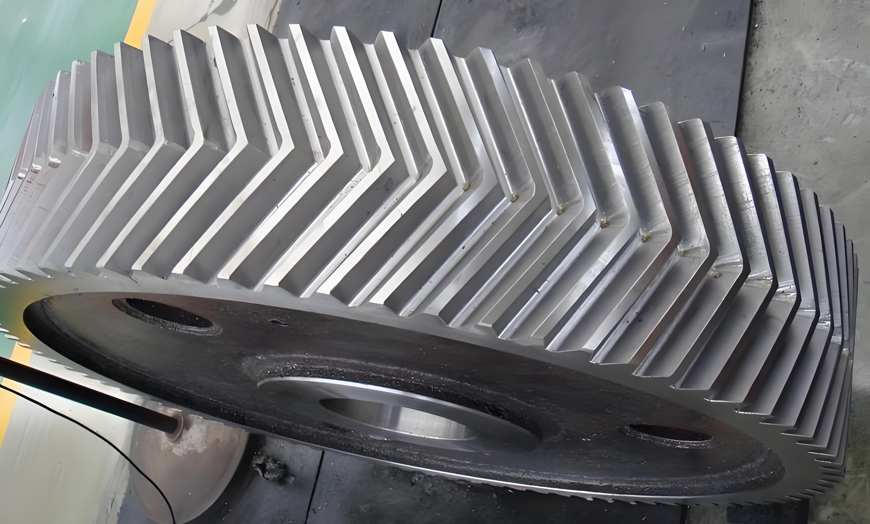
However, the superior load capacity of herringbone gears comes with heightened sensitivity to manufacturing inaccuracies and assembly errors. In a perfect world, the left-hand and right-hand helical sections would engage their respective mating gears simultaneously and share the load equally. In reality, factors like pitch errors, lead errors, and shaft misalignment prevent this ideal condition. One side may contact earlier and bear a disproportionate share of the load, leading to uneven wear, increased vibration, and elevated noise levels. Furthermore, even for a single helical gear, under high loads, teeth deflect elastically, and thermal expansion alters clearances. These effects can cause the theoretical conjugate action to break down, resulting in edge contact at the tips and roots of the teeth, which is a major source of impact noise and stress concentration.
To mitigate these issues and unlock the full potential of herringbone gears, sophisticated design techniques are essential. The two most critical and interrelated techniques are profile modification (or tip/root relief) and Tooth Contact Analysis (TCA). Profile modification involves deliberately and slightly altering the ideal involute tooth profile, typically by removing a small amount of material near the tip and root. This pre-emptive adjustment compensates for the anticipated deflections and errors, ensuring a smooth transition of load from one pair of teeth to the next and preventing harmful edge contact. For practical reasons and to improve efficiency, all modifications are often applied solely to the pinion (the smaller gear). Meanwhile, TCA is a powerful computational simulation tool used to predict the meshing behavior, contact pattern, and transmission error of a gear pair under load, considering the exact geometry, modifications, and assembly errors. It allows engineers to virtually test and optimize the design before physical manufacturing, significantly reducing development time and cost. While TCA is well-established for spur, helical, and bevel gears, its application to herringbone gears, which must account for the interaction between two separate helical meshes, presents unique challenges that require specialized methodology.
Pinion Tooth Profile Modification Using a Modified Rack Cutter
The most practical method for applying profile modifications in mass production is through the cutting tool itself. For gears generated by a rack-type cutter (e.g., hobbing), this involves modifying the straight-line profile of the rack cutter. We employ a three-segment parabolic modification on the pinion, which provides a smooth, continuous relief at the tip and root. The modified rack cutter profile is defined in its normal section, as shown in the coordinate system \( S_c(x_c, y_c) \) fixed to the cutter. The \( y_c \)-axis is the tooth centerline, and the \( x_c \)-axis is aligned with the generating pitch line.
The cutter profile is divided into three zones defined by parabolic segments in the \( y_c(u), z_c(u) \) plane, where \( u \) is the profile parameter (distance from the parabola pole). The equations for these segments are:
$$
\begin{aligned}
\text{Segment 1 (Tip Relief):} & \quad z_{c1} = a_1 u^2 \\
\text{Segment 2 (Central, unmodified region):} & \quad z_{c2} = a_2 u^2 + b_2 u + c_2 \\
\text{Segment 3 (Root Relief):} & \quad z_{c3} = a_3 u^2 + b_3 u + c_3
\end{aligned}
$$
The seven unknown coefficients (\(a_1, a_2, b_2, c_2, a_3, b_3, c_3\)) are determined by applying boundary conditions that ensure continuity and smoothness (C1 continuity) at the junction points \(u = u_1\) and \(u = u_2\), and by specifying the desired maximum relief amounts \(\delta_1\), \(\delta_2\), and \(\delta_3\) at the ends and the central point. The conditions are:
At \(u = u_m\) (where \(|u_m| = \max(|u_1|, |u_2|)\)), the relief equals the specified value, e.g., \(z_{c1}(u_m) = \delta_1\).
At the junction \(u = u_1\): \(z_{c1}(u_1) = z_{c2}(u_1)\) and \(\frac{dz_{c1}}{du}\bigg|_{u=u_1} = \frac{dz_{c2}}{du}\bigg|_{u=u_1}\).
At the junction \(u = u_2\): \(z_{c2}(u_2) = z_{c3}(u_2)\) and \(\frac{dz_{c2}}{du}\bigg|_{u=u_2} = \frac{dz_{c3}}{du}\bigg|_{u=u_2}\).
At a defined point, often the pitch point or a point corresponding to the start of active profile: \(z_{c2}(u_0) = 0\).
Solving this system yields the specific coefficients for the parabolic segments. To obtain the full 3D surface of the rack cutter \( \mathbf{r}_c \), we incorporate a second surface parameter \( l \) representing the lead direction and transform from the normal section to the cutter coordinate system \( S_c(X_c, Y_c, Z_c) \), considering the cutter’s normal pressure angle \( \alpha_n \) and normal module \( m_n \). The surface equation for a segment \( i \) becomes:
$$
\mathbf{r}_c^{(i)}(u, l) =
\begin{bmatrix}
X_c^{(i)} \\
Y_c^{(i)} \\
Z_c^{(i)}
\end{bmatrix}
=
\begin{bmatrix}
l \sin \alpha_n + u \cos \alpha_n \\
l \cos \alpha_n \cos \beta – (z_{ci}(u) + s_n/2) \sin \beta + u \sin \alpha_n \sin \beta \\
l \cos \alpha_n \sin \beta + (z_{ci}(u) + s_n/2) \cos \beta + u \sin \alpha_n \cos \beta
\end{bmatrix}
$$
where \( \beta \) is the helix angle of the gear being generated, and \( s_n \) is the normal tooth thickness on the pitch line. The conditional logic \( i=1 \) for \( u_m \leq u \leq u_1 \), \( i=2 \) for \( u_1 < u \leq u_2 \), and \( i=3 \) for \( u_2 < u \) governs which surface segment is active. It is important to note that for herringbone gears, the pinion has both left-hand and right-hand flanks. Due to potential non-synchronous engagement, it may be beneficial to apply slightly different modifications to the tools cutting the two sides, a flexibility this model accommodates.
Quantification of Pinion Profile Modification
While the tool modification method is efficient, other finishing processes like grinding or skiving might be used. Therefore, it is crucial to define the target modification not as tool coefficients but as the actual deviation on the pinion tooth flank. This deviation is the difference between the coordinates of the modified pinion profile and those of a standard (unmodified) pinion profile at corresponding points along the tooth height.
First, we derive the standard pinion transverse profile generated by a straight-sided rack cutter. The fundamental gear generation relationship establishes that the common normal at the contact point between the rack and the gear blank must pass through the instantaneous center of rotation (the pitch point). From this, the parametric equations for the generated involute profile in the pinion coordinate system \( S_2(X_2, Y_2) \) are:
$$
\begin{aligned}
X_2 &= r_{b1} (\sin \theta – \theta \cos \theta) \\
Y_2 &= r_{b1} (\cos \theta + \theta \sin \theta)
\end{aligned}
$$
where \( r_{b1} \) is the pinion base radius and \( \theta \) is the involute roll angle.
Second, we derive the profile of the pinion generated by the modified (parabolic) rack cutter. The coordinates of the modified rack in its transverse section \( S_t(x_t, y_t) \) are given by transforming the normal profile. The generation process is governed by the equation of meshing, which enforces that the relative velocity between the cutter and the workpiece at the contact point is perpendicular to the common normal. For a rack cutter with a known profile \( \mathbf{r}_t(u) = [x_t(u), y_t(u)]^T \), the equation of meshing is:
$$
\frac{dy_t/du}{dx_t/du} = \tan(\phi – \mu)
$$
where \( \phi \) is the rotation angle of the pinion and \( \mu \) is related to the pressure angle. Solving this equation simultaneously with the coordinate transformation from the rack to the pinion provides the modified pinion profile coordinates \( \mathbf{R}_2(u, \phi(u)) \).
Finally, the profile modification amount \( \Delta \) at a specific point on the pinion flank is calculated. We match points on the standard and modified profiles that lie at the same radial distance \( R \) from the pinion center, or more precisely, have the same length of generating arc on the base circle. The modification is the difference in the profile coordinates in the direction normal to the ideal involute:
$$
\Delta(R) = \| \mathbf{R}_2^{\text{modified}}(R) – \mathbf{R}_2^{\text{standard}}(R) \|
$$
This result \( \Delta(R) \) is the essential specification for any manufacturing process aiming to produce the optimized herringbone gear pinion, providing a clear target for quality control.
| Parameter | Symbol | Description |
|---|---|---|
| Base Circle Radius | \(r_b\) | Radius defining the start of the involute. |
| Roll Angle | \(\theta\) | Parameter for defining a point on the involute. |
| Rack Profile Parameter | \(u\) | Distance along the rack profile from a reference. |
| Pinion Rotation Angle | \(\phi\) | Solved from the equation of meshing. |
| Profile Deviation | \(\Delta\) | Final modification amount normal to the flank. |
Tooth Contact Analysis for Herringbone Gears
Tooth Contact Analysis is the computational cornerstone for predicting the performance of modified herringbone gears. The core challenge lies in modeling the simultaneous yet potentially unsynchronized meshing of the two independent helical gear contacts. We establish a comprehensive coordinate system framework to achieve this.
Consider a pinion and gear forming a herringbone gear pair. The system is decomposed into two separate helical gear meshes: Mesh I (e.g., right-hand pinion with left-hand gear) and Mesh II (left-hand pinion with right-hand gear). For each mesh, we define fixed coordinate systems \( S_{1}^{(I)} \) and \( S_{1}^{(II)} \) attached to the pinion’s rotational axis at the midpoint of its respective helix section. Similarly, the nominal fixed coordinate systems for the gear in each mesh are \( S_{2}^{(I)} \) and \( S_{2}^{(II)} \), initially aligned with their pinion counterparts at the theoretical center distance \( a \).
Assembly errors are critical inputs for a realistic TCA. These include:
- Axis Misalignment (Σ): The small angle between the pinion and gear axes.
- Center Distance Error (Δa): Deviation from the theoretical center distance.
- Axial Shifts (ΔX): Displacement along the axis, crucial for herringbone gears to manage thrust balance or errors.
To incorporate these, we introduce auxiliary fixed coordinate systems \( S_{f}^{(I)} \) and \( S_{f}^{(II)} \) for the gear in each mesh. The transformation from the nominal system \( S_{2}^{(I)} \) to \( S_{f}^{(I)} \) involves translations \( (\Delta E, \Delta G, \Delta X)^{(I)} \) and a rotation corresponding to the axis misalignment \( \Sigma \). The parameters for Mesh II, \( (\Delta E, \Delta G, \Delta X)^{(II)} \), are determined based on the shared axis misalignment \( \Sigma \) and the specific axial shift of the gear member for that mesh. The position vectors of a point on the pinion and gear flanks are expressed in their respective body-attached rotating coordinate systems and then transformed into a common global fixed frame using homogeneous transformation matrices that include the rotational motion parameters \( \phi_1 \) and \( \phi_2 \).
The fundamental TCA equations for a single mesh (e.g., Mesh I) enforce that a point on the pinion surface \( \mathbf{r}_1^{(I)} \) coincides with a point on the gear surface \( \mathbf{r}_2^{(I)} \) at the contact point, and that their unit normals \( \mathbf{n}_1^{(I)} \) and \( \mathbf{n}_2^{(I)} \) are collinear (opposite in direction). This yields a system of five independent scalar equations (three from position, two from the cross product of normals) with six unknowns: the two surface parameters for the pinion \( (u_1, l_1) \), the two for the gear \( (u_2, l_2) \), and the two rotation angles \( \phi_1, \phi_2 \). By parameterizing the solution with one variable, typically the pinion rotation angle \( \phi_1 \), we can solve for the others, obtaining the transmission error \( \Delta \phi_2(\phi_1) = \phi_2(\phi_1) – (N_1/N_2)\phi_1 \) and the path of contact on both tooth flanks.
The analysis for Mesh II is performed identically but with its own set of transformation parameters. The complete behavior of the herringbone gear pair is the aggregate of these two analyses. The load sharing between the two meshes is not implicitly defined by this geometric TCA but requires an additional Loaded Tooth Contact Analysis (LTCA) module that considers tooth stiffness. However, the geometric TCA provides the essential unloaded contact patterns and the kinematic transmission error for each mesh, which are vital indicators of quality. A key output is the comparison of transmission errors from Mesh I and Mesh II; significant differences indicate poor synchronization and potential for uneven load distribution in the herringbone gears.
| Error Type | Symbol | Effect on Herringbone Meshes |
|---|---|---|
| Axis Misalignment (Angle) | \(\Sigma\) | Affects both Mesh I and Mesh II simultaneously, causing separation and misorientation. |
| Center Distance Error | \(\Delta a^{(I)}, \Delta a^{(II)}\) | Can be different for each mesh due to thermal growth or mounting. |
| Axial Shift of Gear | \(\Delta X^{(I)}, \Delta X^{(II)}\) | Critical parameter. Independent adjustment can be used to synchronize contact patterns on both sides of the herringbone gears. |
| Lead Angle Error | \(\Delta \beta\) | Included in the tooth surface geometry, causes bias in the contact pattern. |
Case Study: Validation with Experimental Herringbone Gears
The proposed methodology for design and analysis was validated using a real-world case study of a high-power herringbone gear set designed for marine transmission testing. The basic geometric parameters of the gear pair are summarized below:
| Parameter | Pinion | Gear |
|---|---|---|
| Number of Teeth, \( z \) | 31 | 102 |
| Normal Module, \( m_n \) (mm) | 4.5 | |
| Normal Pressure Angle, \( \alpha_n \) (deg) | 20 | |
| Helix Angle, \( \beta \) (deg) | 28.34 (Right & Left Hand) | 28.34 (Left & Right Hand) |
| Face Width (per helix), \( b \) (mm) | 90 | 90 |
| Hand of Helix | Right & Left | Left & Right |
The pinion was designed with the three-segment parabolic profile modification detailed earlier. The calculated modification curve, expressed as a function of the roll distance along the base circle (which is proportional to the tooth height), was provided as the manufacturing specification. After machining, the actual pinion flank was measured using a coordinate measuring machine (CMM). The measured modification data, when converted and plotted against the same base roll distance, showed excellent agreement with the design curve. Both curves exhibited the characteristic “S” shape: relief at the root (start of engagement), a nearly flat central region (full contact), and relief at the tip (end of engagement). This confirmed the accuracy of the tool design and manufacturing process in achieving the intended flank geometry for the herringbone gear pinion.
Subsequently, a rolling test under light load was conducted on a dedicated gear test rig to visualize the contact pattern. The physical test involved applying a marking compound (e.g., prussian blue) to the teeth and running the gears slowly. The resulting contact pattern on the workpiece was a distinct, centrally located ellipse. Crucially, the pattern showed no contact at the very tip or root edges of the teeth, indicating the modifications successfully prevented edge loading.
In parallel, a geometric TCA simulation was performed using the designed flank data (including modifications) and nominal assembly conditions. The predicted unloaded contact pattern from the simulation was a clear, centralized elliptical patch, remarkably similar in shape, size, and location to the pattern obtained from the physical rolling test. The absence of edge contact in the simulation corroborated the test results. This consistent match between the predicted and actual contact behavior for the herringbone gears validated the entire workflow: from the mathematical definition of the modification, through the TCA simulation methodology accounting for the dual-helix structure, to the final physical performance.
Conclusion and Engineering Significance
The design and analysis of high-performance herringbone gears necessitate an integrated approach combining targeted profile modification and sophisticated contact simulation. This article has detailed a complete methodology, starting with a practical three-segment parabolic modification applied via a modified rack cutter. The derivation of the cutter surface and the subsequent calculation of the resultant pinion flank deviation provide a clear, quantifiable specification for manufacturing, independent of the specific finishing process used.
The core advancement lies in the adaptation of Tooth Contact Analysis for the unique structure of herringbone gears. By establishing a coordinate framework that treats the gear pair as two coupled helical meshes with independently definable assembly errors—particularly axial shifts—the methodology can accurately model the non-synchronous contact conditions that are prevalent in real-world applications. The TCA predicts critical performance indicators such as the unloaded transmission error and contact pattern for each mesh, enabling engineers to diagnose potential issues like uneven load sharing before physical prototyping.
The successful validation through a case study, where designed modification curves matched measured data and simulated contact patterns aligned with experimental rolling tests, demonstrates the robustness and accuracy of the proposed approach. This validated framework serves as a powerful foundation for further advanced studies, such as Loaded Tooth Contact Analysis (LTCA) to compute precise stress distributions and transmission error under load, and ultimately, for the multi-objective optimization of modification parameters to simultaneously minimize noise, maximize strength, and ensure uniform load sharing across both helixes of the herringbone gears. By leveraging these computational tools, the development cycle for these critical components is significantly shortened, cost is reduced, and the reliability and performance of the final product are substantially enhanced.