
In the realm of power transmission for heavy-duty applications, the manufacturing of spiral bevel gears represents a pinnacle of precision engineering. Among the various established gear cutting systems, one that has consistently demonstrated superior performance, particularly for customized or small-batch production, is the system developed by Klingelnberg, based on the Cyclo-Palloid principle. This epicycloidal gear cutting system, producing gears with uniform tooth depth, offers a compelling combination of high precision, manufacturing efficiency, and operational robustness. The unique advantages of this tooth geometry have led to its widespread adoption in demanding sectors such as engineering machinery, mining equipment, and heavy vehicles. At the heart of this manufacturing capability lies a particularly ingenious tool: the two-part universal cutter head, a subject of enduring interest for gear cutting specialists aiming to optimize production processes and gear performance.
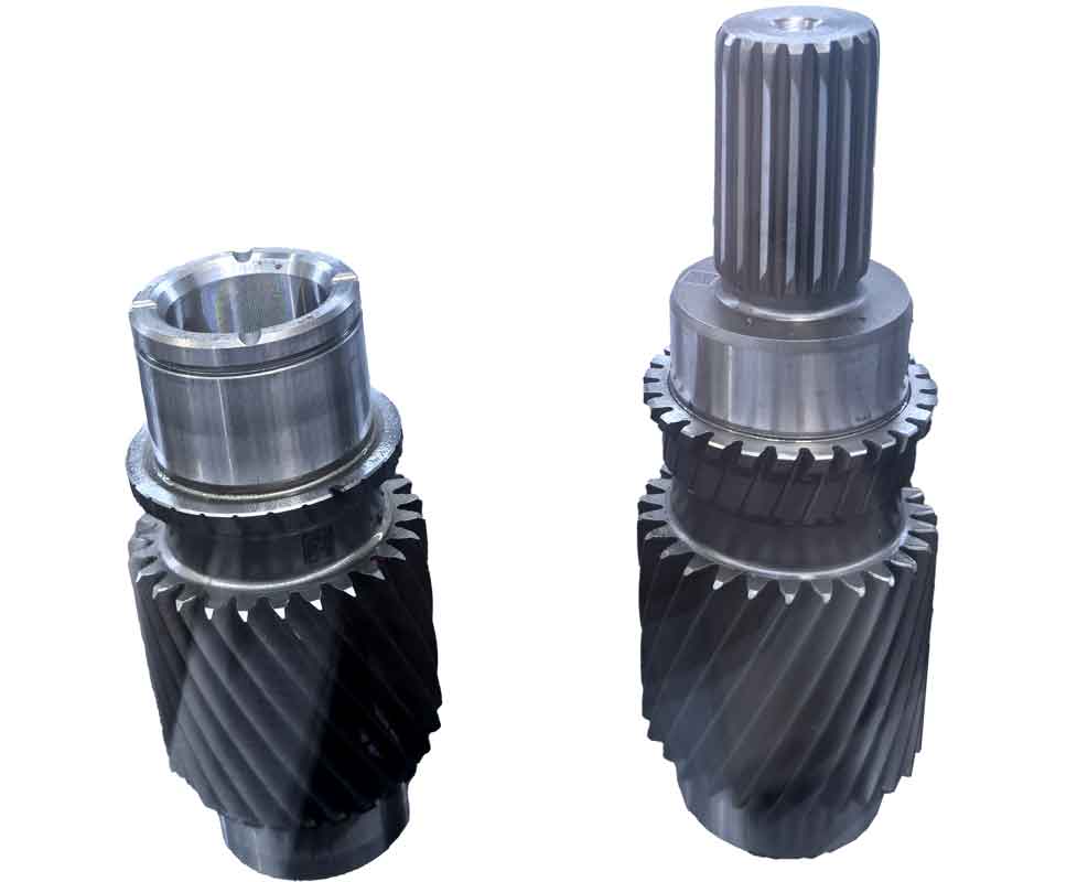
Fundamental Principles and Advantages of the Cyclo-Palloid System
The Klingelnberg Cyclo-Palloid system is fundamentally different from face-hobbing or face-milling processes with fixed setup. Its core principle is continuous indexing gear cutting, where the workpiece and the cutter head maintain a synchronized, continuous rotational relationship throughout the machining cycle. This method contrasts with single-indexing processes, where the workpiece is indexed discretely after each tooth space is cut. The continuous motion eliminates potential errors associated with indexing mechanisms, leading to inherently higher gear quality, superior tooth-to-tooth spacing accuracy, and excellent surface finish. Furthermore, this continuous gear cutting motion significantly enhances production rates, making the process highly efficient even for complex gear geometries.
The geometry of the tooth flank is generated based on the “planar crown gear” or “planar generating gear” principle. In this conceptual model, the gear tooth surfaces are generated as if they were in mesh with a basic crown gear whose tooth flanks are flat. This theoretical foundation greatly simplifies both the machine setup calculations and the physical adjustment of the gear cutting machine. A critical benefit arising from this principle is the inherent avoidance of diagonal contact patterns under load. Instead, the system is designed to produce a localized, oval-shaped contact area in the center of the tooth flank, commonly referred to as a “crowned” or “lengthwise crowning” contact. This intentional crowning is crucial for accommodating minor misalignments, deflections under load, and mounting inaccuracies in the final assembly, thereby ensuring quiet operation and long service life.
The advantages of this gear cutting system can be systematically summarized as follows:
| Advantage Category | Detailed Description |
|---|---|
| Precision & Productivity | Continuous indexing ensures high geometrical accuracy (pitch, profile, helix) and excellent surface finish while simultaneously enabling high production rates. |
| Simplified Engineering | The planar crown gear principle leads to straightforward machine setting calculations and adjustments, reducing setup time and potential for error. |
| Robust Contact Pattern | The generated crowned contact area is tolerant to misalignment and shaft deflection, promotes even load distribution, and is easily modified for optimal performance. |
| Tooling Economy | A single, universal two-part cutter head with a limited set of standard blade groups can produce a wide range of gear sizes and ratios, ideal for small to medium batch gear cutting. |
| Hard Finishing Capability | The process is suitable for hard skiving (or power skiving) of case-hardened gears, allowing for finishing after heat treatment to correct distortions and achieve final high precision at lower cost compared to grinding. |
Anatomy of the Two-Part Universal Cutter Head
The key to the flexibility and efficiency of this gear cutting system is its unique tool design. Unlike solid cutter bodies, the Klingelnberg cutter head is a composite, two-part structure. It consists of an inner and an outer cutter body, concentrically assembled but capable of precise radial offset relative to each other. These two bodies are connected via a special coupling, often a form of face tooth coupling or precision curvic coupling, which ensures perfect synchronization and coaxiality during rotation without the need for keys. The radial offset, or eccentricity, between the two bodies is a controlled and variable parameter, adjusted using calibrated spacer shims. This eccentricity (denoted as ‘e’) is the fundamental parameter that controls the amount of lengthwise crowning imparted to the gear teeth during the gear cutting process.
Within this structure, the outer cutter body is dedicated to mounting the blades that will cut the concave (also called “drive” side for the pinion) flank of the gear tooth. Its rotational axis is offset by the amount ‘+e’ relative to the theoretical machine center. Consequently, its effective cutting radius \( R_2 \) at the mean point of the tooth is:
$$ R_2 = r + e $$
where \( r \) is the nominal, pitch-point radius of the theoretical generating crown gear.
Conversely, the inner cutter body holds the blades that cut the convex (“coast” side for the pinion) flank of the gear tooth. Its rotational axis is offset by ‘-e’, giving it an effective cutting radius \( R_1 \):
$$ R_1 = r – e $$
In many standard setups for simpler applications, the inner body’s offset is zero, making \( R_1 = r \). The critical relationship is the *difference* in effective radii between the inner and outer cuts, which is directly responsible for creating the crowned tooth form. To achieve a conjugate meshing condition at the design mean point ‘M’ between the pinion convex flank and gear concave flank (and vice-versa), the normal vectors to both surfaces at ‘M’ must coincide. This kinematic condition dictates that the instantaneous centers of rotation for the inner and outer cutter blade groups must lie on a straight line passing through the mean generating point.
The physical implementation of the gear cutting process is optimized for productivity. A single cutter head typically accommodates multiple blade groups. A common configuration is five groups (\( z_o = 5 \)) arranged around the circumference of the head. Each group contains four individual blades, performing different functions in sequence as they pass through a single tooth gap during one continuous indexing cycle. The four blades in a standard set are:
- Inner Finishing Blade (A): Finishes the convex flank of the tooth.
- Inner Roughing/Chamfering Blade (B): Pre-cuts the convex flank and helps form the tooth root.
- Outer Roughing/Chamfering Blade (C): Pre-cuts the concave flank and helps form the tooth root.
- Outer Finishing Blade (D): Finishes the concave flank of the tooth.
This arrangement allows for the complete roughing and finishing of a tooth space in a single pass of the cutter head, significantly reducing gear cutting cycle time. The angular spacing between the inner and outer blades within a group is fixed at \( 180^\circ / z_o \) (e.g., 36° for a 5-group head) to maintain the correct phasing for simultaneous generation of both flanks.
| Blade Position in Group | Blade Designation | Primary Function | Flank Machined |
|---|---|---|---|
| 1 | A (Inner Finisher) | Final cut for profile accuracy & finish | Convex |
| 2 | B (Inner Rougher) | Rough cutting and root formation | Convex |
| 3 | C (Outer Rougher) | Rough cutting and root formation | Concave |
| 4 | D (Outer Finisher) | Final cut for profile accuracy & finish | Concave |
Cutter Head Versatility and Spiral Direction
A remarkable feature of this universal cutter head is its ability to cut both left-hand and right-hand spiral gears without changing the head itself. Only the cutting blades and their mounting sequence are changed. The blades are ground specifically for either a left-hand or right-hand spiral. The installation sequence on the head is then determined according to a fixed rule when facing the working side of the cutter head:
- For Cutting a LEFT-HAND Spiral Gear: Blades are mounted in clockwise order as A, B, C, D.
- For Cutting a RIGHT-HAND Spiral Gear: Blades are mounted in clockwise order as C, D, A, B.
This simple rearrangement, combined with corresponding adjustments to the machine’s rotational direction and feed, allows the same universal tool to cover a vast array of gear designs. For specialized high-volume production or specific contact pattern requirements, solid one-piece cutter heads are also used. In such cases, crowning is achieved by using different effective cutter radii (\( R_1 \) and \( R_2 \)) for machining the pinion and gear separately, rather than via an eccentric head.
Determination of the Crowning Eccentricity (e)
The eccentricity ‘e’ is the most critical adjustment parameter in the setup for gear cutting with this system. It directly controls the magnitude of lengthwise crowning \( C_b \), which influences the contact pattern size, shape, and the gear pair’s tolerance to misalignment. An appropriate value of ‘e’ ensures optimal load distribution and promotes the formation of an elastohydrodynamic lubrication film. Deriving the relationship between ‘e’ and \( C_b \) requires an analysis of the tooth geometry in a transverse section.
Consider the meshing of two crowned profiles that are tangent at a mean point M. Let \( R_1 \) and \( R_2 \) be the radii of curvature of the generating profiles (from the inner and outer cutter bodies, respectively) at M. For a tooth flank, the transverse radius of curvature is related to the cutter radius. Let ‘a’ represent half the transverse contact length projected from the mean point. The crowning value \( C_b \) is essentially the deviation of one profile from the other at a distance ‘a’ from the mean point.
Using geometric relations and applying a binomial approximation for simplification, the deviation \( A_1A_2 \) (which equals \( C_b \)) can be expressed as:
$$ A_1A_2 \approx \frac{a^2 (R_1 – R_2)}{R_1 R_2} $$
The half-contact length ‘a’ is related to the face width ‘b’ and the mean spiral angle \( \beta_m \) by:
$$ a \approx \frac{b}{2 \cos \beta_m} $$
Substituting the cutter radii \( R_1 = r – e \) and \( R_2 = r + e \) into the deviation formula, and assuming \( r \gg e \) so that \( R_1 R_2 \approx r^2 \), we get:
$$ C_b \approx \frac{a^2 \cdot ((r-e) – (r+e))}{r^2} = \frac{a^2 \cdot (-2e)}{r^2} $$
Taking the magnitude and substituting for ‘a’:
$$ C_b \approx \frac{ \left( \frac{b}{2 \cos \beta_m} \right)^2 \cdot 2e }{r^2} = \frac{b^2 e}{2 r^2 \cos^2 \beta_m} $$
In practical gear cutting engineering, a more common and direct form of this relationship, derived from the generating kinematics, is often used:
$$ C_b \approx \frac{e \cdot b^2}{8 r^2 \cos^2 \beta_m} $$
Rearranging to solve for the required eccentricity ‘e’ to achieve a desired crowning \( C_b \):
$$ e \approx \frac{8 C_b r^2 \cos^2 \beta_m}{b^2} $$
The desired crowning value \( C_b \) is not a fixed number but is selected based on factors including gear module, face width, material, heat treatment, expected load, and permissible misalignment. In industrial practice, after calculating ‘e’ using this formula, the value is rounded to the nearest multiple of 0.2 mm (or similar increment) to match the available standard thicknesses of adjustment shims supplied with the gear cutting equipment. This standardization minimizes the inventory of shims and reduces setup complexity and potential adjustment errors.
Extended Applications and Process Integration
The versatility of this gear cutting system extends beyond conventional soft machining. The robust design of the cutter head and the stability of the continuous indexing process make it exceptionally suitable for hard finishing operations. After case hardening, gears often exhibit distortion. The Cyclo-Palloid process can be employed for hard skiving (also called power skiving or hard finishing) using specially coated, wear-resistant blades. This subsequent gear cutting operation corrects heat treatment distortions, improves tooth flank geometry, and enhances surface finish, often serving as a more cost-effective alternative to grinding, especially for medium-sized gears and small batch production.
Modern computer-aided engineering (CAE) plays a vital role in optimizing the gear cutting process. Software modules are used to perform advanced tasks such as:
- Load Capacity Optimization: Algorithms can determine the optimal basic geometric parameters (e.g., number of teeth, spiral angle, face width) to maximize torque capacity or minimize size for a given load, directly influencing the subsequent gear cutting setup.
- Contact Pattern Simulation (TCA – Tooth Contact Analysis): Software predicts the contact pattern under load for given machine settings (including ‘e’), allowing engineers to virtually correct and optimize the pattern before physical gear cutting begins, saving time and material.
- Process Simulation: The entire gear cutting cycle can be simulated to predict cutting forces, optimize feed rates, and prevent tool collisions, ensuring efficient and safe manufacturing.
Comparative Analysis with Other Gear Cutting Systems
To fully appreciate the position of the Klingelnberg Cyclo-Palloid system, it is instructive to compare it with other prevalent spiral bevel gear cutting methods.
| System Feature | Klingelnberg Cyclo-Palloid (Continuous Indexing) | Gleason Face Hobbing (Continuous Indexing) | Gleason Face Milling (Single Indexing) |
|---|---|---|---|
| Indexing Method | Continuous | Continuous | Single / Intermittent |
| Tooth Depth | Uniform (等高齿) | Uniform | Tapered |
| Contact Pattern Type | Localized, crowned (Oval) | Typically lengthwise | Lengthwise, can be modified |
| Basic Tooling | Universal 2-part head, few blade types | Solid head, specific to ratio range | Multiple cutter heads & blades per job |
| Setup Simplicity | High (Planar crown gear principle) | Moderate to Complex | Complex |
| Production Rate | Very High | Very High | Lower |
| Ideal Production Volume | Small to Large Batch | Mass Production | Small Batch, Prototype |
| Hard Finishing Suitability | Excellent (Hard Skiving) | Good | Limited |
Conclusion
The Klingelnberg Cyclo-Palloid spiral bevel gear cutting system, centered around its innovative two-part universal cutter head, represents a highly refined and efficient solution for producing high-performance gears. Its strengths lie in the elegant synergy between a theoretically sound generating principle (planar crown gear) and a practical, flexible tool design. The continuous indexing ensures precision and speed, while the adjustable eccentricity of the cutter head provides straightforward control over the crucial crowned contact pattern. The system’s economic advantage is sealed by the remarkable versatility of its tooling, where a minimal set of components can machine a wide spectrum of gear sizes and spiral directions. This makes it particularly advantageous for the medium and small-batch production runs typical in heavy machinery, where reliability, performance, and manufacturing cost are paramount. As material science and digital simulation technologies advance, the integration of this robust gear cutting method with predictive engineering software and hard finishing capabilities continues to solidify its role as a cornerstone technology for manufacturing durable and efficient spiral bevel gear drives for the most demanding applications worldwide.