
In my research and design practice, I have consistently observed that the conventional methodology for designing and manufacturing hyperboloid gears is fundamentally anchored in the principle of zero-displacement. This includes both standard and addendum-modified designs, which are analogous to the zero-displacement concept in involute cylindrical gears. The primary distinction for hyperboloid gears lies in their “radial-tangential” comprehensive zero-displacement condition, typically expressed as the sum of radial displacement coefficients being zero and the sum of tangential displacement coefficients also being zero: $ \sum x_r = 0 $ and $ \sum x_t = 0 $.
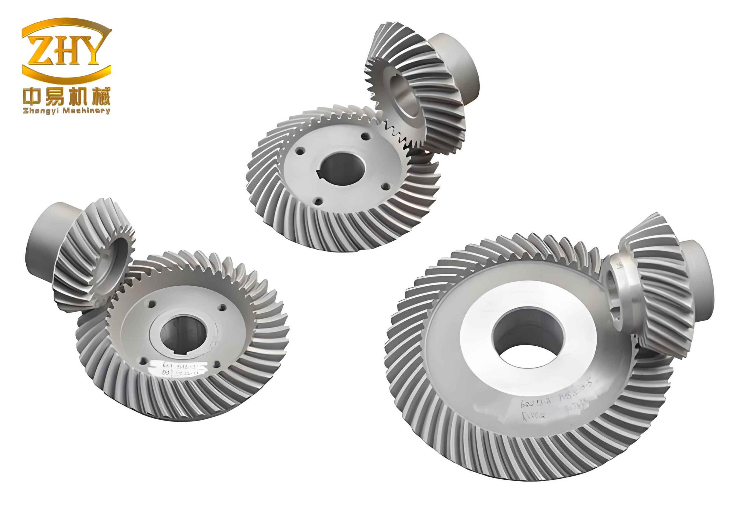
It is widely recognized that angular displacement (non-zero displacement) in involute cylindrical gears offers significant advantages. It allows for a reduction in the total number of teeth without undercutting, thereby enabling more compact gearbox designs. Furthermore, it provides a powerful means to optimize tooth profiles for enhanced bending and surface durability, reduce sliding velocities to improve resistance to wear and scoring, and balance specific sliding. The traditional confinement of hyperboloid gear design to the zero-displacement paradigm inherently limits the potential to maximize performance and unlock the inherent capabilities of these complex gears from a design perspective. Therefore, the introduction of the angular displacement concept from involute gearing into hyperboloid gear design represents a highly effective and economically practical pathway to achieve comprehensive performance goals, including high strength, low wear, low noise, and reduced volume.
Through several years of dedicated investigation, my work has encompassed the following key areas:
- Establishing the fundamental design principle and geometric calculation model for “non-zero displacement” hyperboloid gears, providing detailed methodologies and formulas for blank geometry computation.
- Exploring the methods and corresponding calculations for the practical machining realization of non-zero displacement hyperboloid gears.
- Developing integrated computer-aided design (CAD) and manufacturing (CAM) software tailored for the design and cutting calculation of non-zero displacement hyperboloid gears.
- Applying the non-zero displacement design principle to improve the main reduction gear pair in a vehicle rear axle, conducting a series of studies involving design modification, manufacturing trials, and comparative bench testing, which successfully yielded the anticipated performance enhancements.
This article focuses on elucidating how this new non-zero displacement design methodology can be employed to elevate the comprehensive performance of hyperboloid gears. I will detail the underlying design principles, the geometric model, and essential calculation formulas. Subsequently, I will present an optimization design model aimed at multi-performance objectives. Finally, a practical application case will be discussed, accompanied by numerical results and comparative operational test data.
Fundamental Principles of Non-Zero Displacement Design
The tooth form of a hyperboloid gear at its mean point can be conceived as the intersection of the tooth surface with the back cone. This form is generated by the motion of the cutter and closely approximates a spherical involute. The mean back cone itself is a developable surface. By developing it, we obtain an equivalent pair of very thin crossed helical gears. This virtual gear pair serves as the conceptual counterpart to the hyperboloid gear, with corresponding parameters such as helix angle, pressure angle, and module, albeit with different tooth numbers. To implement non-zero displacement design for hyperboloid gears, we leverage this virtual crossed-axes helical gear pair and introduce the displacement concepts applicable to such gears, thereby arriving at the non-zero displacement design model for hyperboloid gears.
The core distinction from zero-displacement design is the separation of the pitch circle from the dividing circle, and the consequential separation of the manufacturing reference point from the theoretical mean meshing point. The practical implementation method is achieved through a “relative displacement between the pitch cone and the root cone.”
Based on the relative motion relationship of the crossed-axes gear pair, a unique pair of tangent conical surfaces, known as the pitch cones, can be defined at the pitch point P. Their common tangent plane is the pitch plane. Considering a pair of conjugated tooth surfaces $\Sigma_1$ and $\Sigma_2$ meshing at point P, their pitch point parameters must satisfy the following kinematic conditions governing hyperboloid gear meshing:
$$
r_{p1} \sin \beta_1 = r_{p2} \sin \beta_2
$$
$$
\frac{\sin \delta_1}{\sin \delta_2} = \frac{\omega_2}{\omega_1} = \frac{z_1}{z_2}
$$
$$
\Sigma = \delta_1 + \delta_2
$$
where $r_p$ is the pitch radius, $\beta$ is the spiral angle at the pitch point, $\delta$ is the pitch angle, $\omega$ is the angular velocity, $z$ is the number of teeth, and $\Sigma$ is the shaft angle.
Building upon the displacement theory for crossed-axes helical gears and the concept of the virtual gear pair for hyperboloid gears, we can establish the relationship between the dividing circle parameters and the pitch circle parameters under the condition of their separation. For conciseness, the subscripts for pinion (1) and gear (2) are omitted in the following general forms, unless specified.
$$
d = m_n z / \cos \beta
$$
$$
d_p = d + 2 x_r m_n
$$
$$
\tan \alpha_{pt} = \tan \alpha_n / \cos \beta
$$
$$
inv \alpha_{pt}’ = inv \alpha_{pt} + \frac{2 (x_r + x_t) \tan \alpha_n}{z}
$$
Here, $d$ is the reference diameter, $m_n$ is the normal module at the mean point, $\beta$ is the spiral angle at the reference circle, $d_p$ is the pitch diameter, $x_r$ is the radial displacement coefficient, $\alpha_n$ is the normal pressure angle, $\alpha_{pt}$ is the transverse pressure angle at the reference cylinder, $\alpha_{pt}’$ is the operating transverse pressure angle at the pitch cylinder, and $x_t$ is the tangential displacement coefficient.
For a chosen point to function as the pitch point, a normal displacement approach must be adopted. This requires satisfying the following condition regarding the sums of the displacement coefficients for the pinion and gear pair:
$$
\sum x_r = x_{r1} + x_{r2} \neq 0
$$
$$
\sum x_t = x_{t1} + x_{t2} \neq 0
$$
$$
\Delta y = (x_{r1} + x_{r2}) – y
$$
$$
y = \frac{z_1 + z_2}{2 \cos \beta} \left( \frac{\cos \alpha_{pt}}{\cos \alpha_{pt}’} – 1 \right)
$$
where $y$ is the center distance modification coefficient and $\Delta y$ is the addendum modification coefficient.
To maintain a standard tip clearance, the tooth addendum must be adjusted accordingly. The addendum modification coefficient $\Delta y$ is calculated as shown above. The dedendum heights for the pinion and gear are then:
$$
h_{f1} = (h_{aP}^* + c^* – x_{r1}) m_n
$$
$$
h_{f2} = (h_{aG}^* + c^* – x_{r2}) m_n
$$
The addendum heights become:
$$
h_{a1} = (h_{aP}^* + \Delta y – x_{r1}) m_n
$$
$$
h_{a2} = (h_{aG}^* + \Delta y – x_{r2}) m_n
$$
Let the total tooth height be $h = h_{a1} + h_{f1} = h_{a2} + h_{f2}$, and the tip clearance be $c = c^* m_n$. In these formulas, $h_{aP}^*$ and $h_{aG}^*$ are the nominal addendum coefficients for the cutter used for the pinion and gear, respectively, and $c^*$ is the clearance coefficient.
| Design Aspect | Zero-Displacement Design | Non-Zero Displacement Design |
|---|---|---|
| Fundamental Condition | $\sum x_r = 0$, $\sum x_t = 0$ | $\sum x_r \neq 0$, $\sum x_t \neq 0$ |
| Pitch / Dividing Circle | Coincident | Separated |
| Meshing / Manufacturing Point | Coincident (at mean point) | Separated |
| Design Flexibility | Limited, based on standard parameters. | High, allows independent optimization of pressure angle, contact ratio, sliding ratios, etc. |
| Primary Objective | Achieve conjugate meshing with standard tools. | Optimize comprehensive performance (strength, wear, size, noise). |
| Geometric Calculation | Relatively straightforward. | More complex, requires solving for operating pressure angle $\alpha_{pt}’$. |
Comprehensive Performance Optimization Design for Hyperboloid Gears
Designing a high-performance hyperboloid gear pair necessitates the consideration of multiple, often competing, objectives such as volume, bending and contact strength, wear resistance, and anti-scoring capability. This multi-faceted problem complexity typically requires evaluating numerous design alternatives to identify a superior solution. From a practical standpoint, and considering the maturity of conventional hyperboloid gear design—which boasts extensive research, empirical data, and design charts—I advocate for a two-stage design methodology when incorporating non-zero displacement principles.
- Conventional Baseline Design: Conduct an initial design based on application requirements and operating environment using established conventional methods for hyperboloid gears. This stage may involve a small-scale optimization for certain variables if necessary. The output of this stage includes the nominal gear geometry and typically assumes zero-displacement coefficients: $x_{r1}=0, x_{r2}=0, x_{t1}=0, x_{t2}=0$.
- Non-Zero Displacement Coefficient Optimization: Based on specific application targets, employ optimization techniques to select the optimal set of displacement coefficients, thereby performing a comprehensive performance-driven design using the non-zero displacement model.
The following outlines a constrained optimization mathematical model for the synthesis of displacement coefficients in a hyperboloid gear pair. The primary optimization variables are the four displacement coefficients:
$$
\mathbf{X} = [x_{r1}, x_{r2}, x_{t1}, x_{t2}]^T
$$
A comprehensive objective function $F(\mathbf{X})$ can be formulated as a weighted sum of individual performance indices:
$$
F(\mathbf{X}) = \mathbf{W} \cdot [f_1(\mathbf{X}), f_2(\mathbf{X}), …, f_n(\mathbf{X})]^T
$$
where $\mathbf{W}$ is a weighting and scaling coefficient matrix that reflects the relative importance of each performance goal (e.g., minimizing size, maximizing bending strength, minimizing a wear indicator), and $f_i(\mathbf{X})$ are the functions calculating the individual performance metrics. The optimization is subject to the following key constraints, which ensure the design is viable and performs at least as well as the baseline (conventional) design in critical aspects:
| Constraint Type | Mathematical Expression / Description | Purpose |
|---|---|---|
| Bending Strength | $ \sigma_{F1}(\mathbf{X}) \leq \sigma_{F1,0}$, $ \sigma_{F2}(\mathbf{X}) \leq \sigma_{F2,0}$ Where $\sigma_{F,0}$ is the bending stress from the conventional design. |
Ensures bending stress does not exceed the baseline level for both pinion and gear. |
| Contact Strength | $ \sigma_{H}(\mathbf{X}) \leq \sigma_{H,0}$ Where $\sigma_{H,0}$ is the contact stress from the conventional design. |
Ensures contact (pitting) stress does not exceed the baseline level. |
| Balanced Bending Strength | $ \left| \frac{\sigma_{F1}(\mathbf{X})}{\sigma_{F2}(\mathbf{X})} – 1 \right| \leq \varepsilon_\sigma $ Where $\varepsilon_\sigma$ is a small tolerance (e.g., 0.1). |
Promotes equal bending strength between pinion and gear to fully utilize material. |
| Undercut Avoidance | $ x_{r1} \geq x_{r1,min} – \xi$, $ x_{r2} \geq x_{r2,min} – \xi$ Where $x_{r,min}$ is the minimum coefficient to avoid undercut, $\xi$ is a safety margin (~0.1). |
Prevents tooth root undercutting during generation. |
| Tip Sharpness | $ s_{a1}(\mathbf{X}) \geq s_{a,min}$, $ s_{a2}(\mathbf{X}) \geq s_{a,min}$ Where $s_a$ is the tip thickness and $s_{a,min}$ is a limit (e.g., $0.25m_n$). |
Ensures sufficient tooth tip thickness for structural integrity. |
| Contact Ratio | $ \varepsilon_{\alpha}(\mathbf{X}) \geq \varepsilon_{\alpha,min}$, $ \varepsilon_{\gamma}(\mathbf{X}) \geq \varepsilon_{\gamma,min}$ Where $\varepsilon_{\alpha}$ is transverse contact ratio (min ~1.2) and $\varepsilon_{\gamma}$ is total contact ratio (min ~2.0). |
Guarantees smoothness and continuity of power transmission. |
| Variable Bounds | $ \mathbf{X}_{lower} \leq \mathbf{X} \leq \mathbf{X}_{upper}$ Practical limits on displacement coefficients. |
Defines a feasible search space for the optimizer. |
This optimization model is characterized by its relatively small scale (four variables) and high flexibility. It can be easily modified to prioritize different objectives or incorporate additional constraints based on specific application needs. Furthermore, it effectively leverages prior experience or results from previous optimization runs.
Application Case and Results
A practical application involved the main reduction hyperboloid gear pair in a vehicle rear axle. The original, conventionally designed pair had the following key parameters: pinion teeth $z_1=10$, gear teeth $z_2=43$, shaft angle $\Sigma=90^\circ$, mean spiral angle $\beta_m=50^\circ$, mean normal module $m_{nm}=5.35 \text{ mm}$, face width, and standard pressure angle. This vehicle was a modified model, and both calculation and field service indicated insufficient bending strength and severe wear of the gears. The design goal was to improve the comprehensive performance of this hyperboloid gear pair without altering the housing dimensions.
The non-zero displacement design method was applied to redesign this hyperboloid gear pair. According to the improvement requirements and the characteristics of non-zero displacement, an optimization procedure was used to select the optimal displacement coefficients while keeping all other macro-geometric parameters unchanged. The optimization objectives were to increase bending strength and reduce a wear indicator, while ensuring contact strength was not compromised.
| Parameter | Original (Zero-Displacement) Design | Improved (Non-Zero Displacement) Design |
|---|---|---|
| Displacement Coefficients | $x_{r1}=0.00, x_{r2}=0.00$ $x_{t1}=0.00, x_{t2}=0.00$ |
$x_{r1}=+0.32, x_{r2}=-0.28$ $x_{t1}=+0.18, x_{t2}=-0.15$ |
| Bending Stress Coefficient, Pinion | $K_{F1}=1.00$ (Baseline) | $K_{F1}=0.87$ |
| Bending Stress Coefficient, Gear | $K_{F2}=1.00$ (Baseline) | $K_{F2}=0.89$ |
| Contact Stress Coefficient | $K_{H}=1.00$ (Baseline) | $K_{H}=0.95$ |
| Wear Indicator (Relative Sliding) | $I_W=1.00$ (Baseline) | $I_W=0.78$ |
The numerical results demonstrate that the non-zero displacement redesign successfully reduced the bending stress by approximately 12-13%, significantly lowered the wear indicator by about 22%, and also yielded a slight improvement (5%) in contact stress. Subsequent comparative bench testing validated these computational predictions, confirming the effectiveness of the non-zero displacement approach in enhancing the real-world performance and durability of the hyperboloid gear drive.
In conclusion, liberating hyperboloid gear design from the traditional zero-displacement constraint opens a powerful avenue for performance enhancement. The non-zero displacement methodology provides the designer with critical additional degrees of freedom—the radial and tangential displacement coefficients for both members. By systematically optimizing these parameters within a framework that considers bending strength, contact strength, wear resistance, and geometric constraints, significant improvements in the comprehensive performance of hyperboloid gears can be achieved. This approach is particularly valuable for redesigning existing drives for higher durability or downsizing new designs without sacrificing reliability, ultimately leading to more efficient, compact, and longer-lasting gear systems. The successful application in a vehicle rear axle gear serves as a concrete testament to the practical viability and benefits of this advanced design philosophy for hyperboloid gears.