
In the pursuit of advancing robotic actuator technology, my research has focused on the critical components that define performance and reliability. The RV reducer stands as a cornerstone in industrial robotics, enabling precise motion control with high torque transmission. Central to its function are the main bearings, which directly influence the overturning stiffness, fatigue life, and overall durability of the RV reducer. Recognizing the industry’s need for accurate characterization of these bearings, I led the development of a dedicated test bench. This article presents a comprehensive account of the test bench’s design, operational principles, experimental methodology, and results, all from a first-person perspective as the principal investigator. The work aims to provide a robust framework for evaluating RV reducer main bearings, thereby contributing to enhanced design and manufacturing practices.
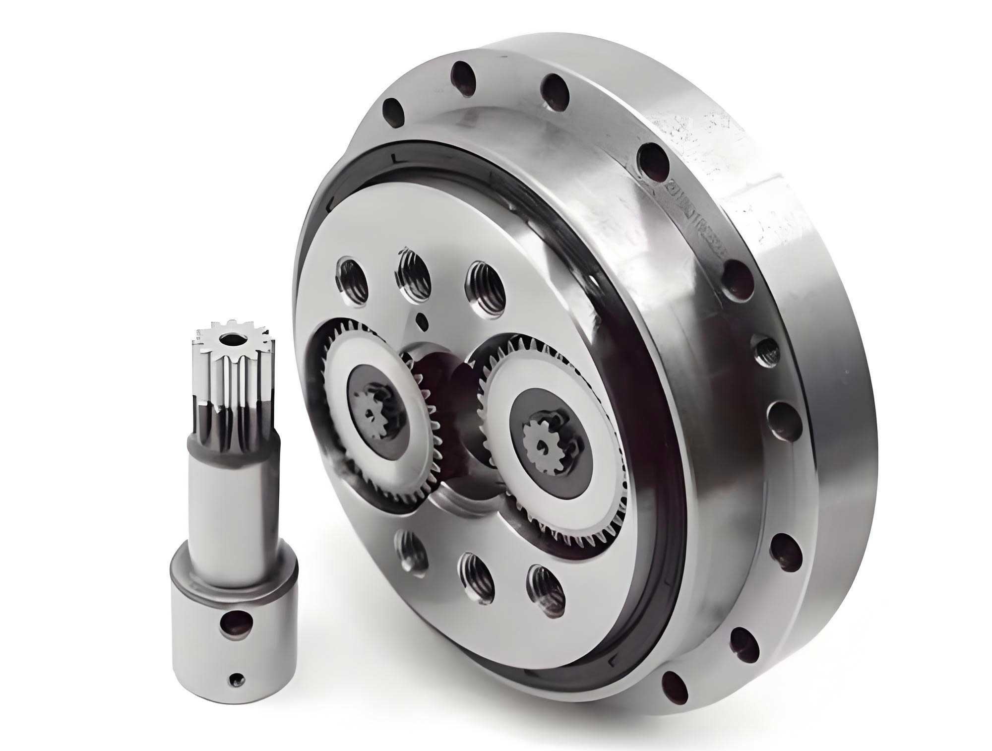
The RV reducer, a complex precision gearbox, integrates a cycloidal drive with a planetary gear stage to achieve high reduction ratios. Its main bearings, typically configured as a paired set of angular contact ball bearings, support the planet carrier and must withstand significant combined loads, including radial forces, axial forces, and overturning moments. The performance metrics of utmost importance are the overturning stiffness, which dictates positional accuracy under load, and the fatigue life, which determines operational longevity. Historically, testing these parameters for an RV reducer has been challenging due to the difficulty in applying controlled, high-magnitude overturning moments and in accurately measuring small angular deflections. My objective was to create a test apparatus that overcomes these limitations, enabling repeatable and precise measurements that correlate with real-world operating conditions for the RV reducer.
Fundamental Testing Principles for RV Reducer Main Bearings
The design of the test bench is rooted in two core experimental principles: the measurement of overturning stiffness and the determination of fatigue life. For overturning stiffness, the RV reducer is subjected to a known overturning moment, and the resulting angular tilt of its output structure is measured. Stiffness is defined as the moment per unit angular deflection. In a typical RV reducer, the main bearings are mounted between the pin housing and the planet carrier. When an external load is applied to the output shaft, it induces a moment that causes the planet carrier to tilt relative to the housing. The overturning stiffness \( M \) is mathematically expressed as:
$$ M = \frac{W_1 l_1 + W_2 l_3}{\theta} $$
Here, \( W_1 \) represents the radial load applied at a distance \( l_1 \) from the central support plane of the main bearings. \( W_2 \) represents the axial load acting at a distance \( l_3 \) from the central axis. \( \theta \) is the measured tilt angle in minutes of arc. A higher \( M \) value indicates a stiffer RV reducer assembly, which is desirable for maintaining precision under load.
For fatigue life testing, the RV reducer is operated under a constant, applied overturning moment and torque for an extended period. The test simulates the demanding conditions experienced by an RV reducer in a robotic joint. Failure is monitored through various indicators such as abnormal temperature rise, increase in lubricant debris (iron powder content), unusual audible noise, or physical seizure. The time to failure under these controlled conditions provides a direct measure of the main bearing’s endurance. The applied load during this test is set at the permissible overturning moment specified for the RV reducer, ensuring the test is representative of maximum operational stress.
Architectural Design and Components of the RV Reducer Main Bearing Test Bench
The developed test bench is a sophisticated integration of mechanical, electrical, and software systems. It adopts a horizontal layout for compactness and ease of operation. The core philosophy was to ensure high structural rigidity for accurate load application and precise sensor measurement, all tailored specifically for the RV reducer.
The mechanical system is constructed on a heavy-duty cast iron surface plate, machined to a high degree of flatness to serve as a stable reference base. The system is modular, comprising several key assemblies: the drive unit, the unit under test (UUT) mounting station, the reaction loading unit, and the measurement instrument mounts. The drive unit incorporates a high-performance servo motor connected via a precision coupling and shaft to the input side of the RV reducer. The output side of the RV reducer is connected to a rigid output shaft supported by a high-stiffness bearing housing. The critical innovation lies in the loading mechanism. Instead of using active servo actuators which can be complex and costly, a passive, mechanically adjustable loading system was designed. This system uses precisely calibrated threaded loaders arranged circumferentially. Applying a known torque to these loaders via a digital torque wrench generates a constant force through a spring-loaded plate. This force acts on a lever arm connected to the output shaft, thereby applying a precise and stable overturning moment to the RV reducer. A force sensor in-line with the loader provides direct measurement of the applied load. This design offers excellent stability, simplicity, and cost-effectiveness for long-duration fatigue tests on the RV reducer.
The electrical control and data acquisition system is built around a Programmable Logic Controller (PLC). The PLC orchestrates the entire test sequence: starting and stopping the servo motor, monitoring safety interlocks, and collecting data from various sensors. Key sensors include a high-resolution dual-axis inclinometer attached to the RV reducer housing and planet carrier to measure tilt angle, a non-contact infrared temperature sensor monitoring the housing, an in-line force sensor for the applied load, and an oil debris sensor (ferrous particle counter) integrated into the RV reducer’s lubrication system to monitor wear progression. All sensor signals are conditioned and fed into the PLC’s analog and digital input modules. The servo motor drive is controlled via pulse train signals from the PLC to achieve the desired rotational speed for the RV reducer.
The supervisory software, developed using a SCADA (Supervisory Control and Data Acquisition) platform, provides the human-machine interface. It features two primary modules: one for stiffness testing and one for fatigue life testing. The interface allows the operator to input test parameters (e.g., RV reducer model, desired load, speed), initiate automated test sequences, and visualize real-time data trends for load, angle, temperature, and particle count. All data is timestamped and stored in a structured database for post-test analysis and reporting. This integrated software approach ensures consistent test execution and reliable data management for every RV reducer evaluated.
| Subsystem | Component | Key Specification / Model | Primary Function |
|---|---|---|---|
| Mechanical | Base Frame & Surface Plate | Cast Iron, Precision Machined | Provides foundational rigidity and alignment |
| Servo Motor & Reducer | High-torque, Low-backlash | Drives the input of the RV reducer under test | |
| Flexible Loading Mechanism | Threaded Loaders with Spring Compensation | Applies precise and stable overturning moment | |
| Precision Bearing Housings | Angular Contact Bearings in Pairs | Supports input/output shafts with minimal deflection | |
| Electro-Sensory | PLC Controller | Modular I/O System | Central control and data logging unit |
| Servo Drive | Digital, Torque/Speed Control | Powers and controls the servo motor | |
| Inclinometer | High-Accuracy Dual-Axis | Measures angular deflection of the RV reducer | |
| Force Sensor | Strain-gauge Based Load Cell | Measures the applied overturning force | |
| Ferrous Particle Sensor | Inductive Sensing Principle | Monitors wear debris in the RV reducer lubricant | |
| Software | SCADA HMI | Custom-developed Application | Test automation, real-time monitoring, data storage |
Experimental Methodology and Results for RV Reducer Evaluation
To validate the test bench, a series of experiments were conducted on a batch of RV-125N type reducers. These RV reducers were manufactured with identical processes, with the main bearing preload as the controlled variable. The test sequence involved both static stiffness measurements and dynamic fatigue life tests.
Overturning Stiffness as a Function of Main Bearing Preload
The preload in the paired main bearings of an RV reducer is a critical assembly parameter. It directly affects internal clearance, contact angles, and ultimately the stiffness and lifespan of the RV reducer. Three RV-125N units were prepared with nominal main bearing preloads of 0.04 mm, 0.06 mm, and 0.08 mm. Each RV reducer was mounted on the test bench. The loading mechanism was used to apply an overturning moment, gradually increasing from zero to the permissible moment of 3430 N·m. At each load step, the corresponding tilt angle \( \theta \) was recorded by the inclinometer. The overturning stiffness \( M \) was calculated in real-time by the software using the formula previously stated. The results clearly demonstrated the relationship between preload and system stiffness for the RV reducer.
| Applied Overturning Moment (N·m) | Overturning Stiffness for 0.04 mm Preload (N·m/’) | Overturning Stiffness for 0.06 mm Preload (N·m/’) | Overturning Stiffness for 0.08 mm Preload (N·m/’) |
|---|---|---|---|
| 500 | 1420 | 1550 | 1680 |
| 1500 | 1580 | 1720 | 1850 |
| 2500 | 1650 | 1800 | 1940 |
| 3430 | 1680 | 1820 | 1960 |
The data shows a consistent trend: increasing the main bearing preload leads to a higher overturning stiffness for the RV reducer. This is expected as preload reduces internal compliance within the bearing assembly. Furthermore, the stiffness is not perfectly linear with load, particularly at lower moment values, which can be attributed to the take-up of internal clearances and micro-deflections in the entire RV reducer structure and test fixture. The stiffness values at full load all exceed the specified minimum of 1600 N·m/’ for the RV-125N, validating the design adequacy.
An additional experiment was performed to assess the variation in stiffness with the rotational position of the RV reducer’s output shaft. Due to inevitable manufacturing tolerances in components like the crankshaft and cycloid discs, the load distribution on the main bearings can vary cyclically. Measuring stiffness at different output angles confirmed this periodic variation, typically within a band of ±3% of the mean value, providing valuable feedback for quality control in RV reducer production.
Fatigue Life Testing and Failure Analysis
A fatigue life test was performed on the RV-125N unit with a 0.06 mm main bearing preload. The test protocol involved applying a constant overturning moment of 3430 N·m and a nominal output torque of 300 N·m, while the servo motor drove the RV reducer at its rated speed of 15 rpm. The test ran continuously, with the supervisory software logging temperature, ferrous particle count, and motor current. The wear process of the RV reducer followed the classical three-stage pattern: initial run-in wear, steady-state wear, and accelerated failure wear.
The initial 50 hours constituted the run-in period, where particle count and temperature showed a slight peak before settling to a stable baseline. For approximately the next 550 hours, the RV reducer operated in a steady state with minimal changes in monitored parameters. A decisive transition occurred at around 605 hours of operation, marked by a sharp, simultaneous increase in housing temperature and lubricant ferrous particle concentration. This indicated the onset of catastrophic wear, and the test was halted. The total runtime of 605 hours was recorded as the fatigue life of this particular RV reducer under the specified test conditions.
Post-test disassembly and inspection revealed the failure mode. The primary failure was identified as fatigue spalling on the raceways of the main bearings, particularly the bearing closer to the load application point. The spalling exhibited classic features: initiated micro-pits that propagated into flaked surface material with visible fatigue striations. The rolling elements (balls) also showed signs of surface distress. This failure mode is consistent with subsurface-originated fatigue due to repeated Hertzian contact stresses exceeding the material’s endurance limit. The test successfully induced and captured a realistic bearing fatigue failure in the RV reducer.
Theoretical Life Modeling and Correlation with Test Data
To contextualize the experimental life, a theoretical model was constructed. The analysis focused on calculating the dynamic loads on the main bearings of the RV reducer under the test conditions. The bearing arrangement involves two back-to-back angular contact ball bearings. The radial loads \( F_{r1} \) and \( F_{r2} \) on the two bearings due to the applied overturning moment \( W_1 l_1 \) and axial load \( W_2 \) can be derived from static equilibrium:
$$ F_{r1} = W_1 \left( \frac{l_1}{g} + \frac{1}{2} \right) + W_2 \frac{l_3}{g} $$
$$ F_{r2} = W_1 – F_{r1} $$
where \( g \) is the distance between the bearing centers. The axial loads are influenced by the radial loads and the induced thrust from the contact angle \( \alpha \). The basic dynamic load rating \( C_r \) for a single row angular contact ball bearing is given by:
$$ C_r = b_m f_c (i \cos \alpha)^{0.7} Z^{2/3} D_w^{1.8} $$
where \( b_m \) is a standard coefficient, \( f_c \) is a factor dependent on geometry and material, \( i \) is the number of bearing rows, \( Z \) is the number of balls per row, and \( D_w \) is the ball diameter. The equivalent dynamic load \( P \) for the bearing is calculated considering both radial and axial components. The rating life \( L_{10} \) (life at 90% reliability) is then:
$$ L_{10} = a_1 a_{ISO} \left( \frac{C_r}{P} \right)^3 $$
The factor \( a_1 \) accounts for reliability (1.0 for 90%), and \( a_{ISO} \) incorporates influences of lubrication, contamination, and material. Crucially, the preload significantly affects the internal load distribution and thus the equivalent load \( P \). A higher preload generally increases the load on the bearings, potentially reducing the calculated \( L_{10} \) life.
Using specialized gearbox analysis software (Masta), a detailed three-dimensional model of the RV-125N reducer was created, incorporating the exact test conditions—fixed housing, applied overturning moment and torque, and the 0.06 mm bearing preload. The software implements the ISO/TS 16281 standard for bearing life calculation, which accounts for detailed load distribution. The simulation predicted a fatigue life of approximately 538 hours for the critical main bearing. Comparing this to the experimentally observed life of 605 hours yields a correlation ratio of 89% (theoretical/actual). This close agreement, within expected margins of variability from material properties and manufacturing nuances, validates both the test methodology and the underlying life prediction models for the RV reducer. It demonstrates that the test bench produces results that are consistent with established engineering theory.
| Parameter | Experimental Value | Simulated (Theoretical) Value | Correlation (Theory/Experiment) |
|---|---|---|---|
| Total Running Hours to Failure | 605 hours | 538 hours | ~89% |
| Failure Indicator | Sharp rise in temperature & particle count | — | — |
| Identified Failure Mode | Main bearing raceway spalling | Calculated bearing fatigue failure | Consistent |
| Main Bearing Preload Setting | 0.06 mm | 0.06 mm (Model Input) | Exact |
Discussion and Implications for RV Reducer Design
The development and deployment of this specialized test bench have yielded significant insights. Firstly, it provides a reliable and repeatable method to quantify the overturning stiffness of an RV reducer. The ability to measure stiffness as a function of preload allows designers to optimize this parameter. A stiffer RV reducer, achieved through higher preload, benefits positional accuracy but, as the fatigue test shows, may trade off against ultimate bearing life. The test bench enables the empirical construction of this trade-off curve for any RV reducer design.
Secondly, the bench facilitates accelerated life testing under realistic combined load states (torque + overturning moment). This is a substantial improvement over traditional test rigs that often apply only pure torque. The failure mode observed—bearing spalling—is the dominant life-limiting failure in correctly manufactured RV reducers, confirming the test’s relevance. Monitoring parameters like ferrous particle count proved to be an excellent prognostic indicator of impending bearing failure in the RV reducer, offering a potential pathway for condition-based maintenance in fielded robots.
The correlation between simulated and experimental life, while not perfect, is sufficiently strong to build confidence in virtual prototyping tools. Discrepancies can be attributed to factors like the statistical nature of bearing fatigue, variations in material microstructure, lubricant film conditions, and the assumed value for the life adjustment factor \( a_{ISO} \). The test bench serves as the essential physical validation tool to calibrate and refine these simulation models for the RV reducer.
Furthermore, the modular and flexible design of the test bench means it can be adapted for different sizes and models of RV reducers by changing fixture plates and adapters. The control software’s architecture also allows for the implementation of more complex duty cycles, such as variable amplitude loading, to better simulate the dynamic loads experienced by an RV reducer in a robot performing varied tasks.
Conclusion
This comprehensive project has successfully resulted in the design, construction, and validation of a dedicated test bench for evaluating the main bearings of RV reducers. The test bench effectively addresses the historical challenges of applying precise overturning moments and measuring minute angular deflections. Through systematic experimentation on RV-125N reducers, it has demonstrated precise measurement of overturning stiffness as a function of bearing preload and has provided a robust method for determining main bearing fatigue life under combined loads. The observed failure modes were consistent with theoretical expectations, and the correlation between experimental life and sophisticated software simulation was strong. This work underscores the critical role of empirical testing in tandem with analytical modeling for advancing the reliability and performance of RV reducers. The test bench stands as a valuable tool for research and development, quality assurance, and design validation, ultimately contributing to the creation of more durable and precise RV reducers for the next generation of industrial robotics.
Future work will involve employing this test bench to study the effects of different lubrication formulations, alternative bearing geometries, and advanced surface treatments on the life and stiffness of RV reducers. Additionally, the collected data will be used to further refine bearing life prediction algorithms, creating a virtuous cycle of testing and model improvement that pushes the boundaries of RV reducer technology.