
Helical gears are an important part of automobile transmissions, providing driving energy such as rotation, transmission, and torque for automobiles. Bearing loss i.e The power loss of the bearing is mainly related to the oil characteristics, the load force, the material deformation and the bearing design. The operation of helical gears often needs to be accompanied by bearing bearing bearing and rotary motion, and the current design of bearing parts is mainly based on theoretical calculations or physical experiments to evaluate the performance, life, wear and other conditions of the bearing, which leads to the consumption of a large number of manpower and material costs at the design end. To this end, scholars at home and abroad have carried out a lot of research on bearing design and manufacturing. Cheng Li et al. proposed an improved fuzzy entropy model based on Sigmoid-like function for rolling bearing degradation feature extraction, and proposed a rolling bearing performance degradation evaluation method based on gray relation to establish the relationship between rolling bearing degradation characteristics and reliability, and the physical experiments show that the improved fuzzy entropy model can effectively extract the performance degradation characteristics of rolling bearings, and the credibility is more than 95%, which provides a reference for bearing performance evaluation modeling and loss analysis. MA et al. discussed that four-point contact ball bearings are a special double-half-inner ring structure with dynamic multi-point contact characteristics in use, resulting in different bearing friction, heat generation and wear rates. In this paper, the traction and contact equations of the balls and the four raceways are established, and the changes of the dynamic contact characteristics of the bearings under complex conditions such as high-speed microload and axial-radial composite load are studied. As the bearing preload increases, the balls and raceways interact with each other
The gradual change from three-point contact to two-point contact is the key factor of bearing friction loss, which provides a reference for the establishment of a mathematical model for bearing friction moment calculation. Based on the AMESim simulation environment, this paper establishes a simulation model for calculating the bearing loss of automotive helical gears to accurately simulate and measure the axial and radial loads at the contact points of automotive helical gears, and project them onto the bearings to calculate the load contribution in the bearing loss. Establish a mathematical model of bearing losses based on radial load, axial load and lubricating oil; Based on the Svenska Kullager Fabriken (SKF) bearing friction moment calculation model, the frictional moment generated in rolling bearings can be calculated more accurately; The Proportion Integration Differentiation (PID) speed control method was used to carry out simulation tests in AMESim, which provided a reference for the simulation measurement and analysis of radial load and axial load of bearings and the design of bearing selection.
1 Automobile helical gear pair and bearing model
1.1 Three-dimensional model of automotive helical gear pair and bearing
As shown in Figure 1, the established automotive helical gear pair and bearing model consists of a small helical gear and two rolling shafts on its transmission shaft Bearing, large helical gear and two rolling bearings on its transmission shaft. It can be seen that in helical gear transmission, there is a positive or negative radial force on the helical gear and the positive or negative torque it generates, and its force and torque will be transmitted to the bearing through the transmission shaft, and the transmission of the helical gear pair depends on the bearing bearing and the rotation that provides a small friction coefficient due to the bearing.
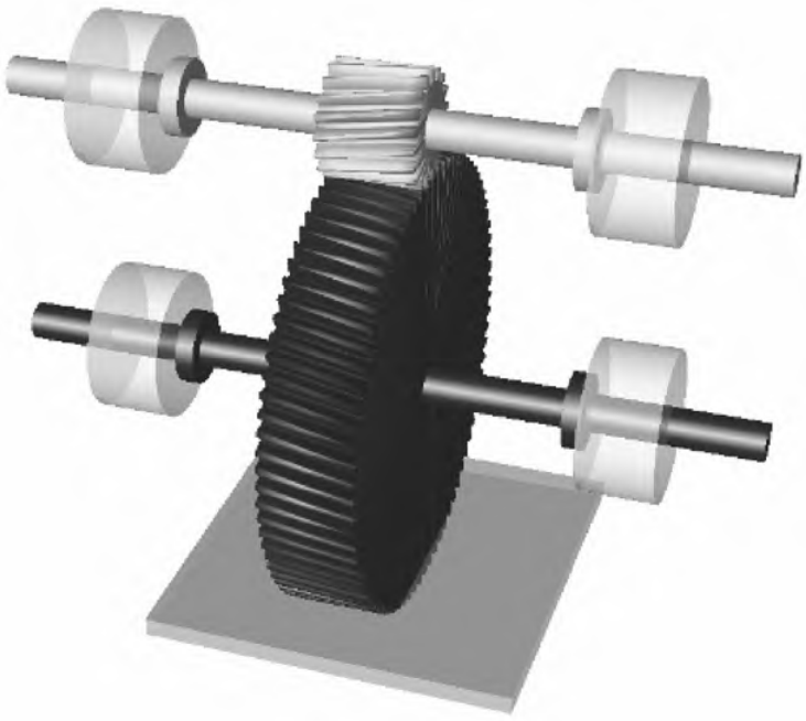
Figure 1 Simplified 3D model of automotive helical gear pairs and bearings
1.2 Bearing loss model
Practice shows that the bearing loses the radial load of the gear pair, the shaft The general expression is that the load is related to the lubricating oil
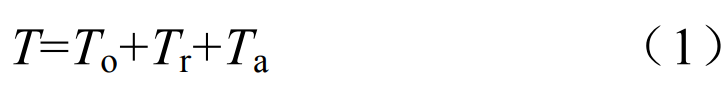
where T is the total torque loss; To is the torque loss due to the lubricating oil; Tr is the torque loss due to the equivalent radial load; Ta is the torque loss due to the equivalent axial load. The torque loss caused by the lubricating oil is proportional to the coefficient of friction f0 and depends on the nature of the oil flow (turbulent or laminar) and is expressed as
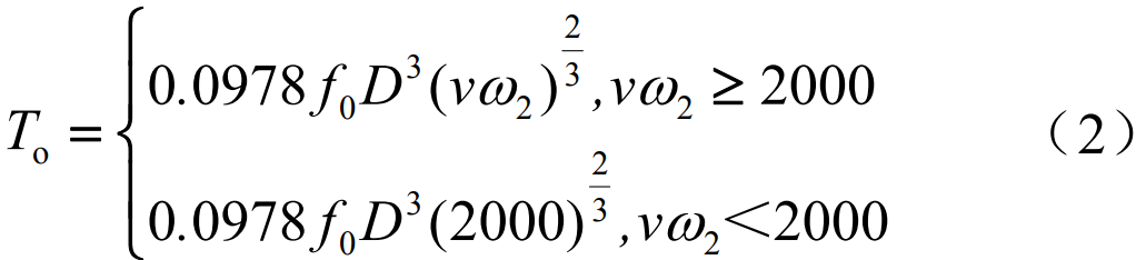
where D is the diameter of the transmission shaft; v is the kinematic viscosity of the lubricating oil; ω2 is the angular velocity of the propeller shaft.
The torque loss due to the equivalent radial load and the torque loss due to the equivalent axial load are
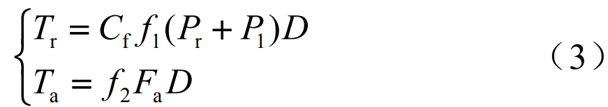
where Cf is the torque loss adjustment factor due to the equivalent radial load; f1 is the coefficient of friction of the radial load; P0 is the equivalent static preload; P1 is the equivalent dynamic load; f2 is the coefficient of friction of the axial load; Fa is the axial load.
1.3 SKF equations
The SKF model, which calculates the frictional moments generated in rolling bearings more accurately, takes into account all the contact areas of the bearing, design changes and improvements, as well as internal and external influences, and thus simulates the real behavior of the bearing. The amount of friction depends on the load, bearing type and size, bearing operating speed, lubricant factors such as properties and the amount of lubricant. The total rotational resistance of the bearing consists of rolling contact, the contact area between the rolling element and the frame, and the rolling and sliding friction in the guide surfaces of the rolling element or frame, the friction in the lubricant and the sliding friction in the contact seal. The expression of the SKF model used to calculate the frictional moment is
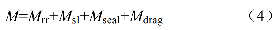
where M is the total frictional moment; MRR is the rolling frictional moment; Msl is the sliding friction moment; Mseal is the sealing friction moment; Mdrag is the frictional moment of resistance loss, agitation, and splashing.The rolling friction moment is calculated according to the formula
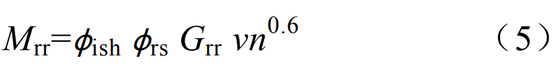
where n is the speed of the transmission shaft; φish is the shear heating reduction factor; φrs motion supply reduction factor; Grr is the rolling friction moment calculation variable, related to the bearing type, the average bearing diameter, the radial force, and the axial direction Force-related can be found in SKF bearing products. Compared to the amount of lubrication available in the bearing, not all lubricants pass through the contact area. Only a small amount of lubricant is used to form a hydrodynamic film. So, some near the entrance to the contact zone The oil is drained, and a countercurrent is created. This reverse flow shears the lubricant and generates heat, which reduces oil viscosity, film thickness and rolling friction. For oil-air, oil injection, low-level oil bath lubrication and grease lubrication methods, continuous over-rolling replaces excess lubricant in the raceway. In higher viscosity or velocity movements, the lubricant may not have enough time to replenish the raceways, resulting in a “motion hunger” effect that reduces the thickness and rolling friction of the hydrodynamic film. The formula for sliding friction moment is
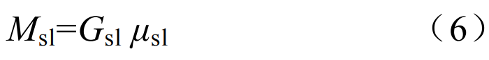
where Gsl is the variable for calculating the sliding friction moment, which is related to the bearing type, the average diameter of the bearing, the radial force and the axial force, which can be found in the SKF bearing products; μsl is the coefficient of sliding friction. The formula for sealing friction moment is
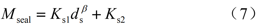
where Ks1 and Ks2 are the constants for calculating the frictional moment; ds is the diameter of the seal face; β is the diameter index of the seal end. The frictional moment of the ball bearing resistance loss can be estimated by the following formula:
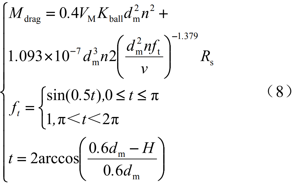
where VM is the drag loss coefficient; Kball is the ball bearing element coefficient; dm is the average diameter of the bearing; H is the oil immersion height of the bearing. Bearings lubricated by the oil bath method are partially submerged or, in exceptional cases, completely submerged. The loss of resistance when the bearing rotates in an oil bath is part of the total frictional moment and should not be ignored. The loss of resistance is not only affected by bearing speed, oil viscosity and oil level, but also by the size and geometry of the reservoir. In addition, consideration should be given to the generation of mechanical elements such as gears or cams in the vicinity of the bearing The external oil is stirred.
1.4 PID Controllers
PID controller is a commonly used control strategy in engineering, in order to realize the loading of excitation signals and closed-loop control in the simulation model, the PID controller is used to realize the speed closed-loop control of the bearing load, and the general model of PID controller is
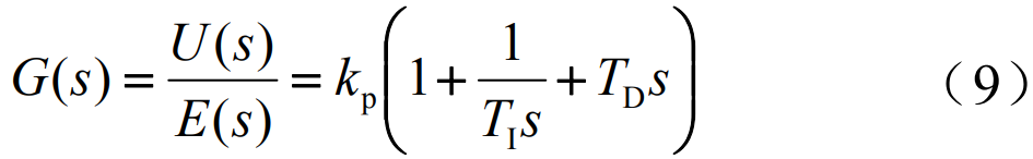
where kp is the proportionality factor; TI is the integration time constant; TD is the differential time constant.
2 AMESim-based simulation model
A simulation model of automotive helical gear bearing loss is set up in AMESim, as shown in Figure 2. The model consists of 2 helical gears forming a gear drive with 2 ball bearings mounted at each end of each of the 2 drive shafts. Set the number of teeth of the small helical gear to 18, the radius of the tooth tip fillet to 17.19 mm, the number of teeth of the large helical gear to 79, the working lateral pressure angle to be 25°, and the helix angle to be 30°.

Figure 2 AMESim-based simulation model of automotive helical gear to bearing loss
Set the two ball bearings on the helical gear shaft with an average diameter of 40 mm, the coefficient of friction depending on the speed is 2, and the coefficient of friction depending on the main load shaft is 2.5e-4; The two ball bearings on the small helical shaft have an average diameter of 40 mm and a coefficient of friction of 2 depending on the speed and 2.5e4 depending on the main load shaft. Set the moment of inertia of the load on the small helical shaft to be 1 kg·m2 and the viscous friction coefficient to be 0.01 N·m/(r/min). Set the controller to PI control, the proportional control coefficient is 10, the integral control coefficient is 0.1, the control output range is -100~100, and the PID controller adopts the time The interval is 1 ms. The speed of the small helical gear shaft is set to control as shown in Figure 3, and the speed rises linearly from 0 r/min to 150 r/min within 0~1 s. The rotation speed is 150 r/min unchanged for 1~4 s; The rotational speed decreases linearly from 150 r/min to -150 r/min in 4~6 s. The rotation speed is -150 r/min unchanged in 6~8 s. In 8~10 s, the rotation increased linearly from -150 r/min to 0 r/min. The rotational speed is unchanged at 0 r/min for 10~12 s. The simulation model adoption period is set to 0.01 s, and the total simulation time is 12 s.
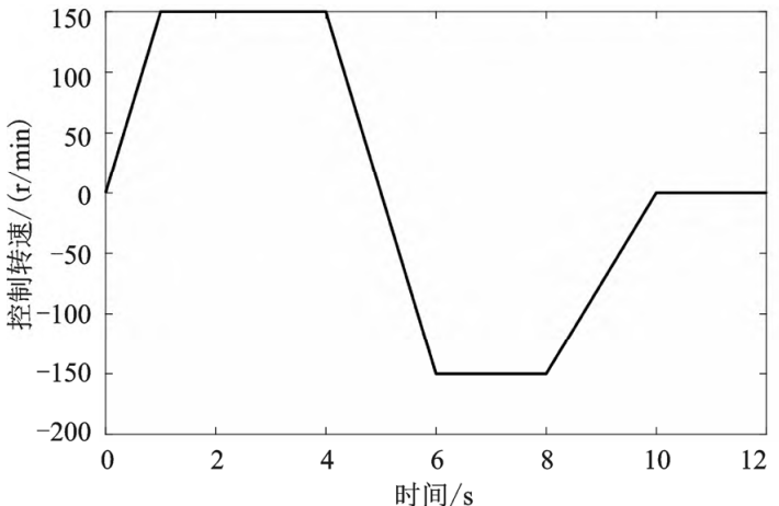
Figure 3 Controlling the rotational speed
As shown in Figure 4, it can be seen that the introduction of the PID controller makes the tracking speed and the control speed change curve maintain good consistency, and the change curve is smooth, and there is no obvious burr phenomenon, and the control accuracy is high.
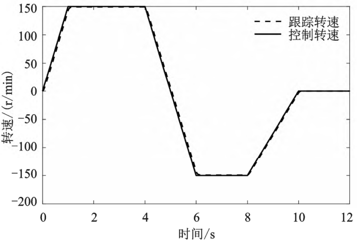
Figure 4 PID Controller Trace Curve
The axial and radial forces projected onto the bearing are obtained from the axial and radial forces at the gear contact on the small helical shaft, as shown in Figure 5. It can be seen that the force on the bearing changes with the change of the control speed, which is in 0~1 s The axial and radial forces gradually increase when the rotational speed increases linearly from 0 r/min to 150 r/min. In 1~4 s, the force gradually decreases to steady state when the rotation speed is 150 r/min unchanged. The steady-state value is around 9 N; The axial force and radial force gradually increase when the rotational speed decreases linearly from 150 r/min to -150 r/min in 4~6 s. The rotation speed is -150 r/min unchanged in 6~8 s The force gradually decreases to a steady state in time, and the steady state value is about 9 N. The rotational speed increases linearly from -150 r/min to 0 r/min in 8~10 s. The rotation speed is 0 r/min in 10~12 s, and the force gradually decreases to a steady state in the constant time, and the steady-state value is about 0 N. It can be seen that with the acceleration and deceleration process of the rotating shaft, the force on the bearing will change abruptly, and the sudden trend is often to increase the load on the bearing, and with the stability of the speed, the load on the bearing is stable in a small force value range.
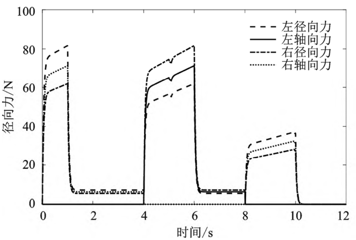
Fig. 5 Axial and radial forces on small helical shaft bearings
The axial and radial forces projected onto the bearing are obtained from the axial and radial forces at the gear contact on the large helical shaft, as shown in Figure 6. It can be seen that the change trend of the force on the bearing is consistent with the axial and radial force of the small helical gear shaft bearing, only the maximum force and the steady state force value are different, the force steady state value is 10~20 N, and the maximum value is about 150 N.
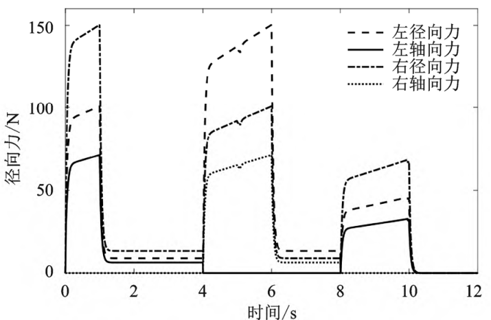
Fig. 6 Axial and radial forces on large helical shaft bearings
3 Concluding remarks
In this paper, based on the AMESim simulation environment, a simulation model of the bearing loss of the contact load of the helical gear of the automobile is established. The bearing loss model and the SKF frictional moment calculation model are discussed. By adding a PID controller to the simulation model, the speed of the transmission shaft is controlled in a closed loop. The transmission shaft variable speed motion simulation test was carried out. The PID controller tracks the curve and performance, and the axial and radial forces on the gear pair due to the contact force of the gear are transmitted to the bearing through the propeller shaft. The results show that the PID controller The velocity effect of high precision is achieved, and the bearing force change curve that conforms to the actual motion situation is obtained, which provides a reference for the simulation study of the bearing loss of automobile gear on contact load.