
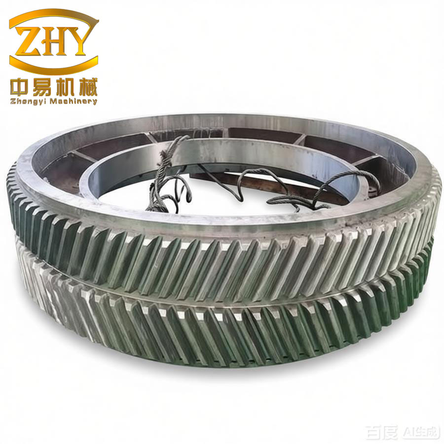
In my research on the free-form milling of herringbone gears, I have focused on understanding how gear clamping pose errors affect the machining accuracy and on developing a simple yet effective compensation method. Herringbone gears are widely used in high-load transmission systems due to their high load capacity, excellent transmission stability, and low axial thrust. However, their manufacturing precision is critical to avoid unilateral meshing and axial runout. Through a combination of theoretical modeling, numerical simulation, and cutting experiments, I have demonstrated that the proposed compensation technique can elevate the gear accuracy from Grade 8 to Grade 5 while significantly improving symmetry between the upper and lower helical teeth.
Introduction
The free-form milling process breaks the limitations of traditional gear manufacturing, which requires dedicated cutters with special geometry. By using standard end mills on multi-axis CNC machines, herringbone gears can be produced at lower cost and with greater flexibility. However, the accuracy of the resulting gear is highly sensitive to clamping pose errors, which are introduced during each workpiece setup. These errors are unavoidable and vary from one clamping to another. Unlike thermal or kinematic errors that can be minimized by hardware compensation (e.g., closed-loop grating scales), clamping pose errors must be addressed through software correction in the NC code.
In this work, I first established a mathematical model of involute herringbone gears and the enveloping principle for flank milling. Using self-developed software, I generated the cutter location (CL) data. I then built a gear clamping pose error model and analyzed the relationship between tooth deviations and four types of clamping errors: tangential position error, radial position error, pitch angle error, and roll angle error. Based on multi-body system theory, I derived an analytical solution for compensation by reverse decoupling the kinematic chain of a five-axis machine tool. Finally, I validated the method through cutting experiments on a herringbone gear with specific parameters.
Mathematical Model of Involute Herringbone Gear and Flank Milling
The herringbone gear consists of two helical gear halves: an upper right-handed helix (RH) and a lower left-handed helix (LH). The tooth profile on the transverse plane is an involute. For a given point on the actual gear surface, I define the tooth deviation as the difference between the actual and theoretical involute lengths.
Let the base circle radius be \( r_b \), the base circle tooth space half-angle be \( \sigma_0 \), and the involute parameter be \( u \). The deviation \( f \) at a point \( G'(x’, y’) \) on the actual tooth flank is computed as:
$$
f = G’T – GT
$$
where
$$
G’T = \sqrt{(x’_G)^2 + (y’_G)^2 – r_b^2}
$$
$$
u = \left| \arctan\left( \frac{y’_G}{x’_G} \right) \right| + \arctan\left( \frac{G’T}{r_b} \right) – \sigma_0
$$
$$
GT = r_b u
$$
This deviation is measured along the normal direction of the involute. The evaluation of gear accuracy follows ISO 1328-1:1995, which defines the following parameters: total profile deviation \( F_\alpha \), profile form deviation \( f_{f\alpha} \), profile slope deviation \( f_{H\alpha} \), total lead deviation \( F_\beta \), lead form deviation \( f_{f\beta} \), lead slope deviation \( f_{H\beta} \), single pitch deviation \( f_{pt} \), cumulative pitch deviation \( f_{pk} \), and total cumulative pitch deviation \( F_p \).
The flank milling process uses a flat-end mill moving along a helical path relative to the workpiece. The cutter location (CL) data are generated from the gear geometry. In the ideal case, the tool‑workpiece relative motion is purely helical. However, if the gear is misaligned on the rotary table, the actual tool path deviates, causing systematic errors in the tooth surface.
Modeling of Gear Clamping Pose Errors
I considered a five-axis machine tool of the RTTTR type (rotary table, tilt table, and three linear axes). The coordinate systems are defined as follows:
- \( o_g-x_g y_g z_g \): actual workpiece coordinate system (including clamping errors).
- \( o_C-x_C y_C z_C \): rotary table (C-axis) coordinate system.
- \( o_A-x_A y_A z_A \): tilt table (A-axis) coordinate system.
- \( o_T-x_T y_T z_T \): tool coordinate system.
In the ideal initial state, the workpiece coordinate system coincides with the rotary table coordinate system. Clamping errors are modeled as four components: tangential displacement \( \delta x_g \), radial displacement \( \delta y_g \), pitch angle error \( \varepsilon_{xg} \) (rotation about x-axis of the workpiece), and roll angle error \( \varepsilon_{yg} \) (rotation about y-axis). The transformation matrix from the workpiece coordinate system to the rotary table coordinate system (including errors) is:
$$
^{i}E_{ag} = \text{Trans}(\delta x_g, \delta y_g, 0) \cdot R_y(\varepsilon_{yg}) \cdot R_x(\varepsilon_{xg})
$$
where Trans and R are 4×4 homogeneous translation and rotation matrices, respectively.
The kinematic chain of the machine is: workpiece → C-axis → A-axis → linear axes → tool. Using homogeneous transformations, I express the tool orientation (unit vector K) and tool tip position (vector Q) in the workpiece coordinate system as:
$$
[K,0]^T = (^{i}E_{ag})^{-1} \cdot R_z(-C) \cdot {}^{C}_{B}A \cdot R_x(A) \cdot {}^{A}_{B}T \cdot [0,-1,0,0]^T
$$
$$
[Q,1]^T = (^{i}E_{ag})^{-1} \cdot R_z(-C) \cdot {}^{C}_{B}A \cdot R_x(A) \cdot {}^{A}_{B}T \cdot [0,0,0,1]^T
$$
By solving these equations and extracting the compensation model, I obtained the modified NC code for the machine axes (A, C, x, y, z) in terms of the original CL data and the measured clamping errors. The analytical solution is:
$$
A = -\arcsin\left( K_x \varepsilon_{yg} – K_y \varepsilon_{xg} + K_z \right)
$$
$$
C = \arctan\left( \frac{K_x – K_z \varepsilon_{yg}}{K_y + K_z \varepsilon_{xg}} \right)
$$
$$
x = \cos(C)(Q_x – \delta x_g – Q_z \varepsilon_{yg}) – \sin(C)(Q_y – \delta y_g + Q_z \varepsilon_{xg}) – \delta x_g
$$
$$
y = \cos(C)(Q_y – \delta y_g + Q_z \varepsilon_{xg}) – \sin(C)(-Q_x + \delta x_g + Q_z \varepsilon_{yg}) + L_y \cos(A) – L_z \sin(A) – L_y – \delta y_g
$$
$$
z = Q_z + L_z \cos(A) – L_z + L_y \sin(A) + Q_x \varepsilon_{yg} – Q_y \varepsilon_{xg}
$$
These formulas directly compensate for the four clamping errors. For a four-axis machine (without the A-axis), only the position errors can be compensated; angle errors must be minimized mechanically by ensuring flatness and perpendicularity of the fixture.
Effect of Clamping Pose Errors on Herringbone Gear Accuracy
I simulated the herringbone gear with parameters: module \( m_n = 4\,\text{mm} \), number of teeth \( z = 13 \), pressure angle \( \alpha = 20^\circ \), helix angle \( \beta = 30^\circ \), correction coefficient \( x_n = 0 \), face width \( b = 50\,\text{mm} \), evaluation start diameter \( d_f = 56\,\text{mm} \), evaluation end diameter \( d_a = 68\,\text{mm} \). The theoretical scallop height was set to 1 μm.
I introduced each clamping error separately and observed the resulting tooth deviations. The key findings are summarized in the following tables.
Tangential Position Error (\( \delta x_g = 0.05\,\text{mm} \))
| Deviation | Upper RH flank | Lower LH flank |
|---|---|---|
| \( f_{H\alpha} \) (μm) | 25.1 | 25.1 |
| \( f_{H\beta} \) (μm) | 20.82 | -20.82 |
| \( f_{f\alpha} \) (μm) | 0.8 | 0.8 |
| \( f_{f\beta} \) (μm) | 0.5 | 0.5 |
| \( F_\alpha \) (μm) | 25.6 | 25.6 |
| \( F_\beta \) (μm) | 21.2 | 21.2 |
| \( f_{pt} \) (μm) | 5.3 | 5.3 |
| \( F_p \) (μm) | 32.1 | 32.1 |
Tangential position error strongly affects \( f_{H\alpha} \) and \( f_{H\beta} \), with magnitudes nearly half of the error. The slope deviations on the upper and lower flanks are identical in magnitude for \( f_{H\alpha} \), but opposite in sign for \( f_{H\beta} \) due to the reversed evaluation order. The form deviations \( f_{f\alpha} \) and \( f_{f\beta} \) are insensitive. Symmetry between upper and lower teeth is not compromised by this position error.
Radial Position Error (\( \delta y_g = 0.05\,\text{mm} \))
| Deviation | Upper RH flank | Lower LH flank |
|---|---|---|
| \( f_{H\alpha} \) (μm) | 24.9 | 24.9 |
| \( f_{H\beta} \) (μm) | 24.9 | -24.9 |
| \( f_{f\alpha} \) (μm) | 0.7 | 0.7 |
| \( f_{f\beta} \) (μm) | 0.6 | 0.6 |
| \( F_\alpha \) (μm) | 25.4 | 25.4 |
| \( F_\beta \) (μm) | 25.3 | 25.3 |
| \( f_{pt} \) (μm) | 5.1 | 5.1 |
| \( F_p \) (μm) | 31.5 | 31.5 |
Results are similar to the tangential case: slope deviations are sensitive, form deviations are small, and symmetry remains intact.
Pitch Angle Error (\( \varepsilon_{xg} = 0.03^\circ \))
| Deviation | Upper RH flank | Lower LH flank |
|---|---|---|
| \( f_{H\alpha} \) (μm) | 15.2 | 15.2 |
| \( f_{H\beta} \) (μm) | 28.6 | -28.6 |
| \( f_{f\alpha} \) (μm) | 0.6 | 0.6 |
| \( f_{f\beta} \) (μm) | 1.2 | 1.2 |
| \( F_\alpha \) (μm) | 15.5 | 15.5 |
| \( F_\beta \) (μm) | 29.0 | 29.0 |
| \( f_{pt} \) (μm) | 3.8 | 3.8 |
| \( F_p \) (μm) | 22.4 | 22.4 |
Angular errors have a more pronounced effect on the lead slope deviation \( f_{H\beta} \) than on the profile slope deviation \( f_{H\alpha} \). Importantly, they introduce asymmetry between the upper and lower teeth, particularly visible in the lead form deviation \( f_{f\beta} \).
Roll Angle Error (\( \varepsilon_{yg} = 0.03^\circ \))
| Deviation | Upper RH flank | Lower LH flank |
|---|---|---|
| \( f_{H\alpha} \) (μm) | 22.5 | 22.5 |
| \( f_{H\beta} \) (μm) | 15.3 | -15.3 |
| \( f_{f\alpha} \) (μm) | 0.5 | 0.5 |
| \( f_{f\beta} \) (μm) | 0.9 | 0.9 |
| \( F_\alpha \) (μm) | 22.8 | 22.8 |
| \( F_\beta \) (μm) | 15.8 | 15.8 |
| \( f_{pt} \) (μm) | 2.6 | 2.6 |
| \( F_p \) (μm) | 17.1 | 17.1 |
Again, angular errors cause asymmetry in the lead deviation. The lead form deviation on the upper and lower flanks is identical in magnitude but the evaluation yields opposite signs. This asymmetry is critical for herringbone gear performance, as it leads to unbalanced axial forces and increased noise.
Compensation Method for Clamping Pose Errors
The compensation approach directly modifies the NC code using the analytical solution derived in Section 3. The procedure is as follows:
- Measure the actual clamping pose errors using dial indicators or a touch probe. In my experiment, the measured errors were: \( \delta x_g = 0.009\,\text{mm} \), \( \delta y_g = 0.02\,\text{mm} \), \( \varepsilon_{xg} = -0.007^\circ \), \( \varepsilon_{yg} = 0.019^\circ \).
- Generate the initial CL data from the gear geometry without errors.
- Apply the compensation formulas to compute the corrected machine axis positions (A, C, x, y, z) for each CL point.
- Output the corrected NC code for machining.
The compensation is realized entirely in the post-processor, without modifying the CNC controller or adding hardware. This method is computationally efficient and can be applied to any five-axis machine with a similar kinematic structure.
Cutting Experiments and Verification
To validate the compensation method, I performed cutting experiments on a five-axis machining center. A flat-end mill with diameter \( \phi 4\,\text{mm} \) was used. The machine was warmed up for 30 minutes to minimize thermal effects. The process included roughing, slotting, and finishing with a scallop height of 1 μm. The gear was clamped on a rotary table, and the clamping errors were measured before machining.
After machining, the gear was measured on a WENZEL LH1512 coordinate measuring machine. Four teeth (positions 1, 4, 7, 10 in the cutting order) were evaluated according to ISO 1328-1:1995. The results for the uncompensated and compensated cases are summarized below.
Uncompensated Results
| Parameter | Value (μm) | Grade (ISO) |
|---|---|---|
| Total profile deviation \( F_\alpha \) | 12.3 | 8 |
| Total lead deviation \( F_\beta \) | 18.5 | 8 |
| Total cumulative pitch deviation \( F_p \) | 44.6 | 8 |
| Parameter | Value (μm) | Grade (ISO) |
|---|---|---|
| Total profile deviation \( F_\alpha \) | 8.5 | 7 |
| Total lead deviation \( F_\beta \) | 5.2 | 5 |
| Total cumulative pitch deviation \( F_p \) | 48.5 | 8 |
Without compensation, the upper and lower teeth exhibited different accuracy grades, indicating poor symmetry. The overall accuracy was dominated by the upper teeth, which were Grade 8 in all three criteria.
Compensated Results
| Parameter | Value (μm) | Grade (ISO) |
|---|---|---|
| Total profile deviation \( F_\alpha \) | 4.8 | 5 |
| Total lead deviation \( F_\beta \) | 6.1 | 5 |
| Total cumulative pitch deviation \( F_p \) | 18.2 | 5 |
| Parameter | Value (μm) | Grade (ISO) |
|---|---|---|
| Total profile deviation \( F_\alpha \) | 4.5 | 5 |
| Total lead deviation \( F_\beta \) | 5.8 | 5 |
| Total cumulative pitch deviation \( F_p \) | 17.9 | 5 |
After compensation, both upper and lower teeth achieved Grade 5 or better. The symmetry between the two halves was greatly improved, as evidenced by the close agreement in all deviation values. The form deviations \( f_{f\alpha} \) and \( f_{f\beta} \) did not show significant improvement because they are inherently insensitive to clamping errors, as predicted by the simulation. The compensation primarily corrected the slope and pitch deviations, which are the main contributors to the total deviations.
Discussion and Conclusion
Through my study, I have demonstrated that clamping pose errors have a major impact on the tooth slope deviations and pitch deviations of herringbone gears, while form deviations remain largely unaffected. Angular errors (pitch and roll) are particularly harmful because they break the symmetry between the two helical halves, leading to increased axial vibration and noise. Position errors, though they cause large slope deviations, do not affect symmetry.
The proposed compensation method, based on reverse decoupling of the kinematic chain, provides an analytical solution that can be implemented in any post-processor. The cutting experiment confirmed that the method can elevate the gear accuracy from Grade 8 to Grade 5 and restore symmetry between the upper and lower teeth. This is a cost-effective way to improve herringbone gear quality without upgrading hardware.
One limitation is that the method relies on accurate measurement of clamping errors. In practice, these errors can be measured with dial indicators or on-machine probing. For four-axis machines, only position errors can be compensated; angle errors must be minimized by careful fixturing. Future work should consider the coupling effect of cutting forces, which also influence the final tooth surface. Integrating force-induced error compensation with the present geometric error compensation will further enhance the machining accuracy of herringbone gears.
In summary, the key contributions of this research are:
- Quantification of how each clamping pose error affects herringbone gear tooth deviations, including the identification of asymmetry sensitivity to angular errors.
- Derivation of a simple analytical compensation formula using multi-body theory.
- Experimental verification that the compensation improves the herringbone gear accuracy from Grade 8 to Grade 5 and significantly enhances symmetry.
- A practical method that can be directly applied in industry to produce high-precision herringbone gears using free-form milling on five-axis CNC machines.