
Abstract
This comprehensive article delves into the analysis and optimization of the contact mode and stress distribution in helical gear through tooth tip modification. Helical gears, known for their superior load-bearing capacity and smooth transmission, play a pivotal role in various mechanical systems. However, contact stress irregularities during meshing can significantly affect the gears’ performance and durability. This study establishes a mathematical model for a helical gear pair with linear tooth tips and utilizes finite element analysis (FEA) and KissSoft software to evaluate the impact of tooth tip modification on contact stress. By meticulously analyzing and modifying the tooth profiles, this research aims to achieve optimal contact stress distribution and improve overall gear performance.
1. Introduction
Gears are fundamental components in mechanical systems, transmitting power and torque between rotating shafts. Among different gear types, helical gear is widely used due to their superior load-bearing capacity, smoothness of operation, and ability to handle high speeds and torques. The helical arrangement of the teeth generates an axial thrust during operation, which, while necessary for the gears’ functionality, can also introduce complexities in contact stress management.
To ensure reliable and efficient power transmission, it is essential to analyze and optimize the contact stress distribution in helical gear. One effective method for achieving this is through tooth profile modification, particularly tooth tip modification. This study explores the effects of tooth tip modification on the contact mode and stress distribution in a single-stage helical gear pair.
2. Helical Gear Design and Modeling
This section outlines the design parameters and modeling process for the helical gear pair under investigation. The gear pair consists of a pinion (small gear) and a gear (large gear). The design parameters for both gears are summarized in Table 1.
Table 1: Design Parameters of the Helical Gear Pair
| Parameter | Pinion | Gear |
|---|---|---|
| Module (mm) | 2 | 4 |
| Number of Teeth | 20 | 40 |
| Addendum Modification | 0.5 | 0 |
| Normal Pressure Angle | 20° | 20° |
| Helix Angle | 15° | 15° |
| Face Width (mm) | 20 | 50 |
| Lead Modification (mm) | 0 | 0 |
| Tooth Tip Width Mod. | Variable (Ca) | Variable (Ca) |
| Tooth Tip Length Mod. | Variable (La) | Variable (La) |
The gear teeth were modified at the tips to optimize contact stress distribution. the tooth tip and lead modifications, where Ca represents the tooth tip width modification, La the tooth tip length modification, and E the lead modification.
3. Mathematical Modeling of the Helical Gear Pair
A mathematical model was developed to represent the helical gear pair with linear tooth tips. The model incorporated geometric parameters such as module, number of teeth, pressure angle, helix angle, and tooth modifications. The equations governing the tooth profiles and their modifications were derived using standard gear geometry principles.
The involute profile of a helical gear tooth can be described mathematically as:
r(θ)=rb[1+(θm)2−1]
where rb is the base circle radius, θ is the involute angle parameter, m is the module, and r(θ) represents the radial distance from the gear center to a point on the tooth profile.
Tooth tip modifications were introduced by adjusting the tooth profile near the tip to achieve a desired linear profile. This modification was modeled by adding a linear segment to the involute profile.
4. Contact Stress Analysis
To evaluate the effectiveness of tooth tip modification in improving contact stress distribution, both finite element analysis and KissSoft software were employed.
4.1 Finite Element Analysis
A finite element model of the helical gear pair was created using commercial FEA software. The gear pair was meshed with high-density elements at the tooth contact regions to accurately capture stress concentrations. Boundary conditions were applied to simulate the gear’s operating conditions, including applied torque and constraints to restrict undesired motions.
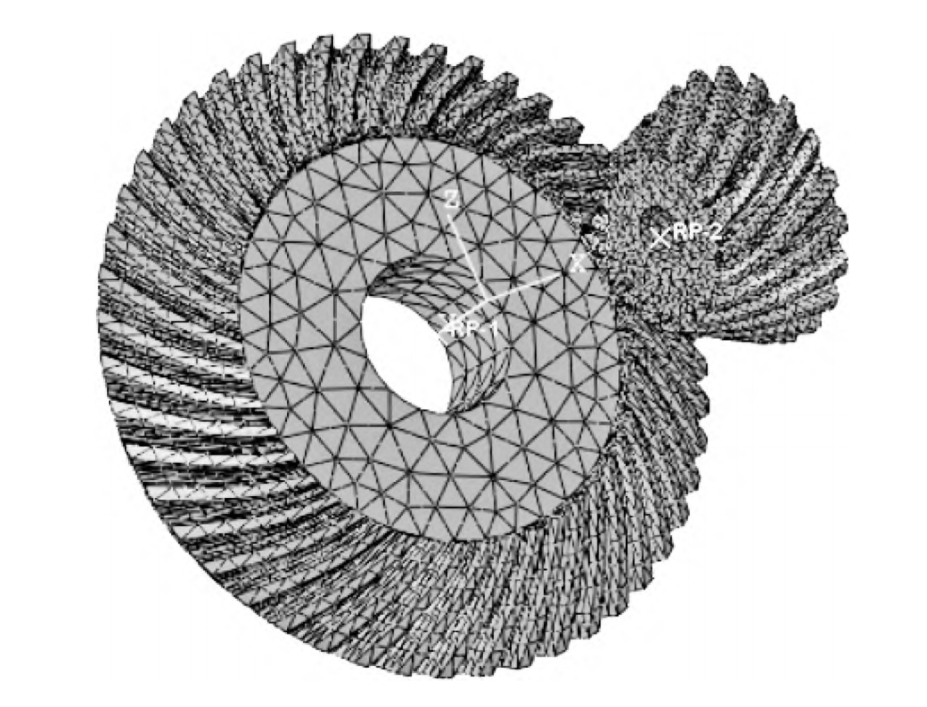
The FEA model incorporated the modified tooth profiles, with specific values for Ca, La, and E based on initial design considerations. the FEA model and the mesh detail near the tooth contact region.
Figure 3: Finite element model and mesh detail of the helical gear pair.
The simulation results provided a detailed map of contact stress distribution over the tooth surfaces. the contact stress contours on the pinion and gear, respectively, during a specific stage of meshing.
4.2 KissSoft Prediction
KissSoft, a specialized gear design and analysis software, was used to predict contact stress distributions in the helical gear pair. The software utilizes advanced algorithms to simulate gear meshing, accounting for various geometric and operational parameters.
The same design parameters and modifications used in the FEA model were input into KissSoft. The software provided a comprehensive analysis of the gear’s contact pattern, load distribution, and contact stress levels throughout the meshing cycle.
5. Comparison and Analysis
The results from both FEA and KissSoft were compared to evaluate the effectiveness of tooth tip modification in improving contact stress distribution.
5.1 Stress Distributions
The maximum contact stresses predicted by FEA and KissSoft are summarized in Table 2. The slight difference between the two methods can be attributed to the inherent assumptions and simplifications in each approach.
Table 2: Maximum Contact Stress Predictions
| Method | Maximum Contact Stress (MPa) |
|---|---|
| FEA | 986 |
| KissSoft | 1021 |
| Difference | 3.5% |
The close agreement between the two methods validates the FEA model and the effectiveness of KissSoft in predicting gear contact stress.
5.2 Contact Patterns
Both FEA and KissSoft revealed similar contact patterns during gear meshing. the contact patterns predicted by FEA and KissSoft, respectively, at various rotation angles.
The contact patterns show that tooth tip modification effectively redistributed contact stress, reducing peak stress concentrations and improving overall stress uniformity.
6. Optimization of Tooth Tip Modification
To further optimize the tooth tip modification parameters (Ca, La, and E), a parametric study was conducted. Various combinations of Ca, La, and E were tested using both FEA and KissSoft, and their effects on contact stress distribution were analyzed.
Based on the parametric study, optimal values for Ca, La, and E were determined that minimized peak contact stress and improved stress uniformity. These optimal values were then used to update the gear design.
7. Conclusion
This study comprehensively analyzed and optimized the contact mode and stress distribution in a helical gear pair through tooth tip modification. By combining finite element analysis and KissSoft predictions, the effectiveness of tooth profile modifications in redistributing contact stress was demonstrated.
The results indicate that optimal tooth tip modification can significantly improve the performance and durability of helical gear by reducing peak contact stresses and enhancing stress uniformity. This approach has the potential to enhance the design and optimization of helical gear in various mechanical systems.