Introduction
In mechanical transmission systems, gear transmission, pulley transmission, and chain transmission are the three most prevalent mechanisms. Among these, gear transmission stands out for its high efficiency, smooth operation, and compact design, making it the most widely utilized form of power transmission. Gears come in various tooth profiles, including involute, circular arc, and cycloidal, with the involute tooth profile being the most common due to its constant transmission ratio. This article delves into the formation of the involute curve, the meshing process of involute gears, and the analysis of critical parameters such as the line of action, contact ratio, and meshing phenomena.

1. Formation of the Involute Curve
The involute of a circle is a fundamental geometric concept that forms the basis of involute gears. To understand its formation, consider a straight line (known as the generating line) rolling without slipping along the circumference of a base circle. As the generating line rolls, any point A on this line traces out a path called the involute curve. Specifically, the arc AK in Figure 1 represents the path traced by point A, which is the involute curve.
Key Characteristics of the Involute Curve:
- Tangent Property: At any point on the involute curve, the perpendicular drawn from that point intersects the base circle tangentially.
- Inner Exclusion: The involute curve does not exist inside the base circle.
- Length Equivalence: The length of the arc AB is equal to the length of the straight line KB.
2. The Meshing Process of Gears
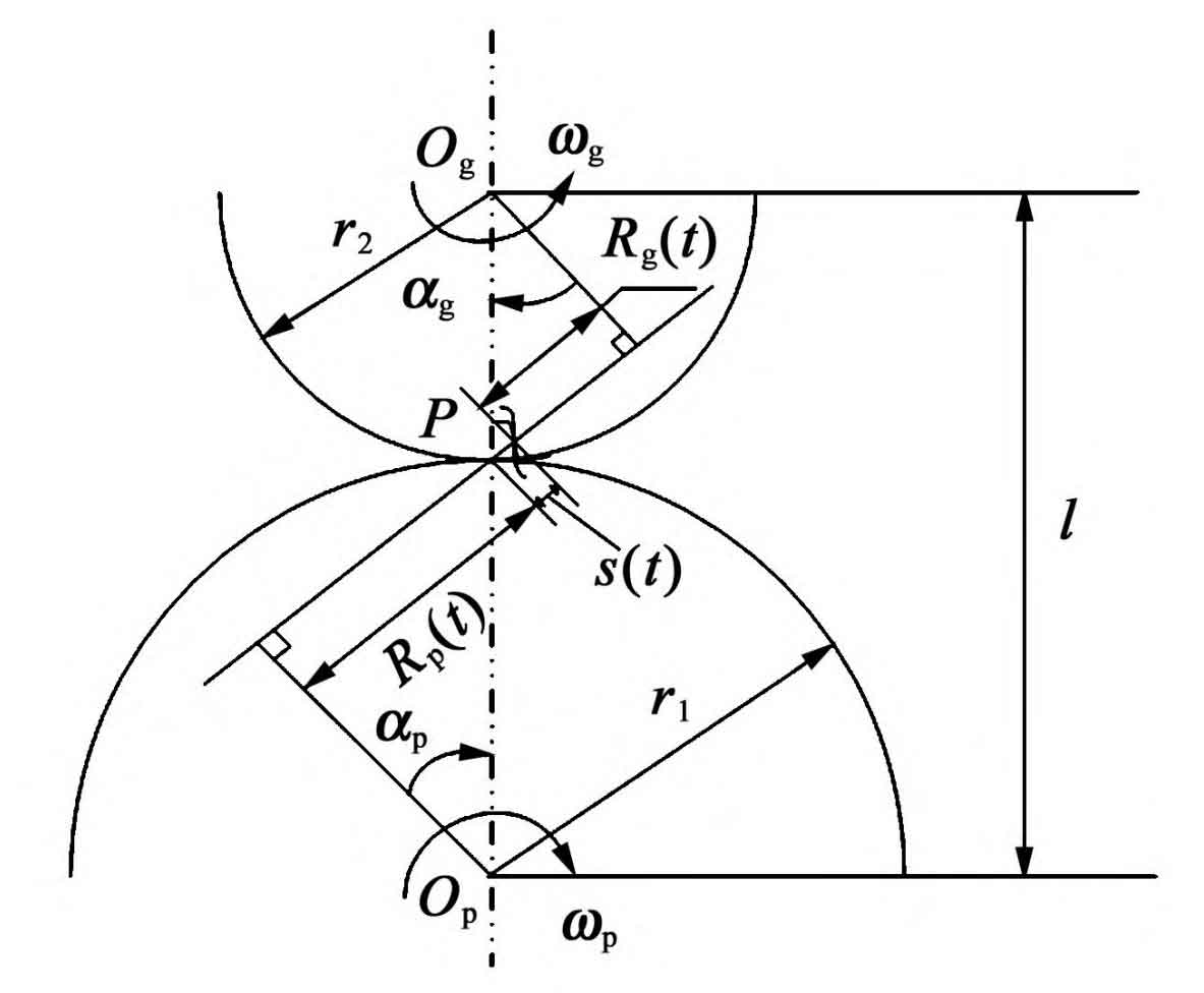
In a typical gear meshing scenario, two gears engage with each other—one as the driving gear (rotating clockwise) and the other as the driven gear (rotating counterclockwise). The inner common tangent between the base circles of these two gears, denoted by N1N2, is known as the theoretical line of action. The actual meshing points lie within this line segment, with B1 representing the starting point of meshing (where the tip of the driven gear intersects the theoretical line of action) and B2 representing the ending point (where the tip of the driving gear intersects the theoretical line).
As the gears rotate, the meshing points move along the theoretical line of action, with the meshing point on the driving gear moving towards its tooth tip, and the corresponding point on the driven gear moving towards its tooth root. The segment B1B2 constitutes the actual line of action, which is a subset of the theoretical line of action. For continuous transmission, the disengagement of one tooth pair must coincide with the engagement of the subsequent tooth pair.
3. Analysis of Contact Ratio and Meshing Parameters
3.1 Definition and Calculation of Contact Ratio
The contact ratio (ε) is a crucial parameter that measures the continuity and smoothness of gear transmission. It is defined as the ratio of the length of the actual line of action (B1B2) to the pitch of the base circle (pb). For smooth and continuous transmission, the contact ratio should be at least unity (ε ≥ 1), with higher values indicating better continuity and stability. In general manufacturing practice, the recommended contact ratio for gear transmission lies between 1.3 and 1.4 (i.e., ε ≥ [ε], where [ε] ≈ 1.3–1.4).
The contact ratio can be calculated using the formula:
ϵ=pbB1B2
where pb=πmcosα is the pitch of the base circle, m is the module, and α is the pressure angle. Alternatively, for standard gears with known tooth numbers (Z1 and Z2) and tooth tip pressure angles (αa1 and ( \alpha_{a2} )), the contact ratio can be approximated using:
ϵ=2πZ1(tanαa1−tanα)+2πZ2(tanαa2−tanα)
where α is the meshing angle, typically 20° for standard installations.
3.2 Analysis of Meshing Parameters
To illustrate the variation of meshing parameters and their influence on contact ratio, consider the following table summarizing the key factors:
| Parameter | Description | Effect on Contact Ratio |
|---|---|---|
| Tooth Numbers (Z1, Z2) | Number of teeth on the driving and driven gears | Directly proportional |
| Pressure Angle (α) | Angle between the tooth profile and the radius at the pitch point | Inversely proportional |
| Tooth Tip Pressure Angles (αa1, αa2) | Angles at the tooth tips of the driving and driven gears | Directly proportional |
| Module (m) | Ratio of the pitch diameter to the number of teeth | Directly proportional |
4. Meshing Phenomena and Transmission Efficiency
During the meshing process, several phenomena occur that can affect transmission efficiency and gear wear. These include:
- Interference and Undercutting: Incorrect tooth profiles or misalignments can lead to interference or undercutting, reducing contact ratio and causing increased wear.
- Backlash: Clearance between meshing teeth to allow for lubrication and compensate for manufacturing inaccuracies. Excessive backlash can lead to reduced transmission efficiency.
- Sliding Friction: Friction between meshing teeth results in power loss and wear. Minimizing sliding friction through proper lubrication and tooth profile design is crucial.
5. Conclusion
The analysis of the meshing process of involute gears reveals the importance of understanding geometric parameters and their relationship to transmission efficiency and gear wear. By optimizing the contact ratio and minimizing interference, undercutting, and sliding friction, engineers can design gear systems that are efficient, reliable, and durable.
In summary, the involute gear design, with its constant transmission ratio and smooth meshing characteristics, remains a fundamental component in mechanical transmission systems. Through careful analysis of meshing parameters and phenomena, engineers can continue to enhance the performance and lifespan of these critical mechanical components.
