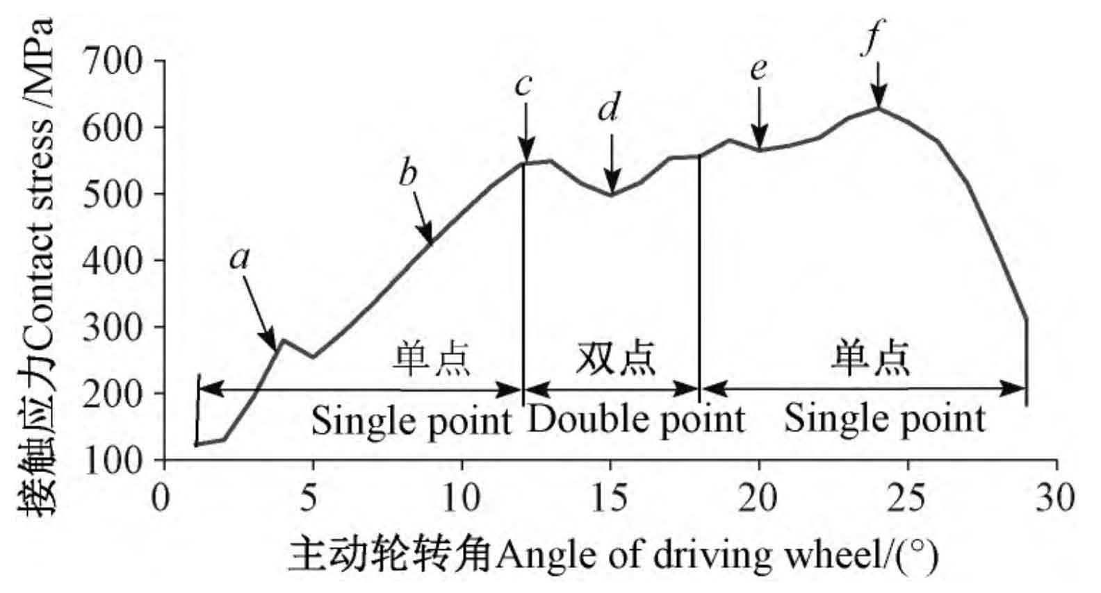
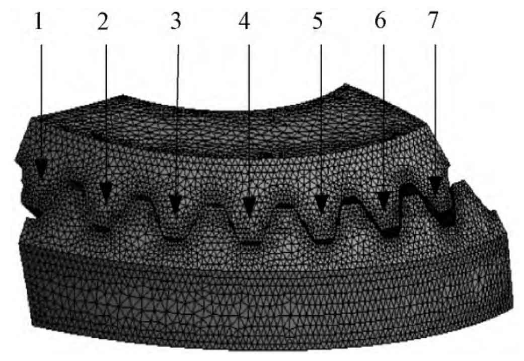
Take the intermediate tooth (No. 4 tooth pair) of the double-arc spiral bevel gear in Figure 1 as the analysis object, and obtain the change curve of the instantaneous maximum contact stress of the tooth surface contact state in one meshing cycle and the entire gear tooth at the corresponding meshing time, and the results are shown in Figure 2 and Figure 3 respectively. Among them, Figures 2a to 2f correspond to the time of a to f in Figure 3.
It can be seen from Figure 2 that in one meshing cycle, the tooth surface of the gear tooth experiences three contact states, namely, single point contact, double point contact and single point contact. Specifically, when the gear tooth meshing is in the first single-point contact stage, the double-arc spiral bevel gear meshes from the large end of the convex tooth surface, and the contact area changes along the tooth width direction, as shown in Fig. 2a and Fig. 2b. As the force on the tooth surface increases gradually with the meshing process, the contact stress also increases.
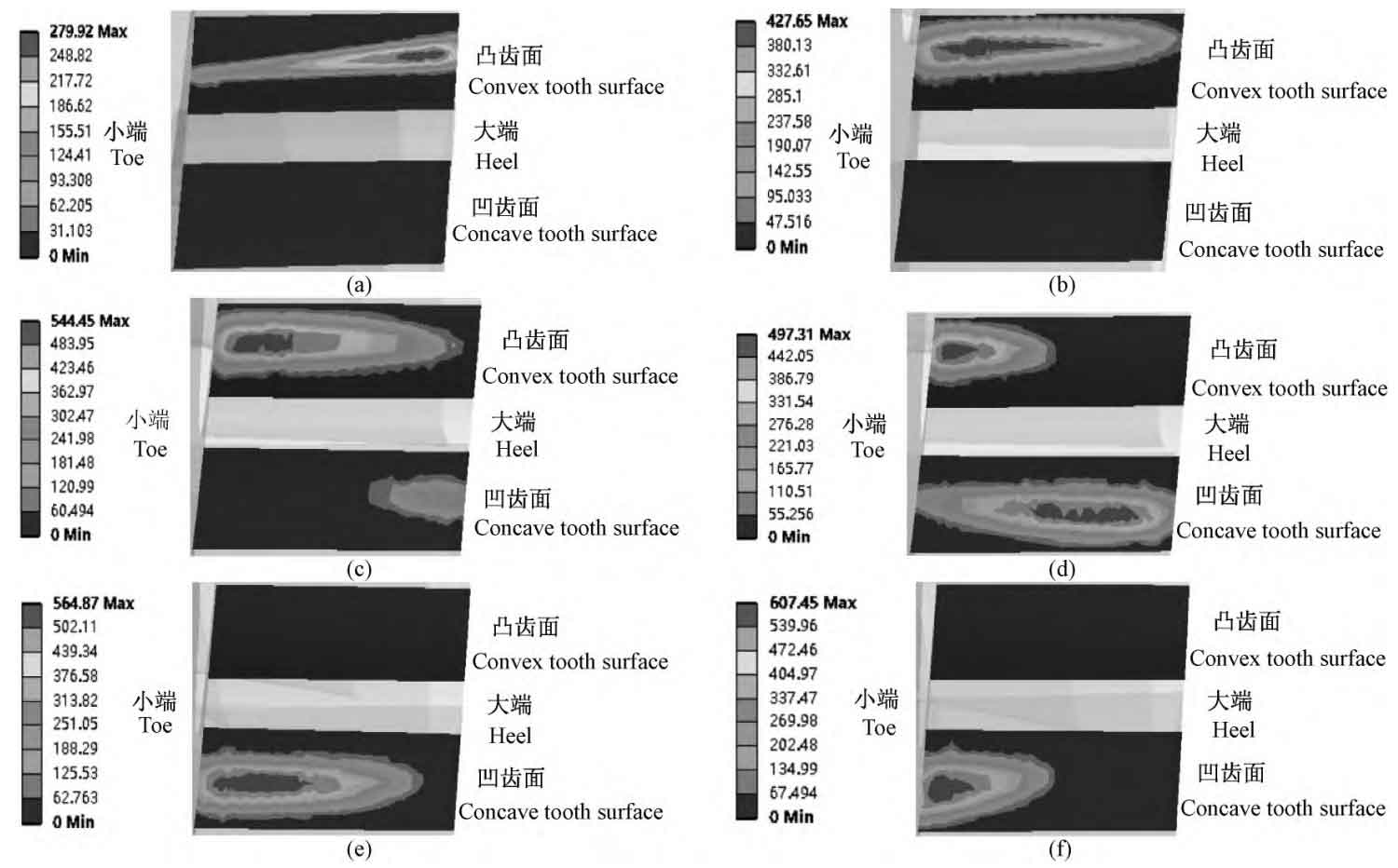
When entering the two-point meshing state, as shown in Figure 2c, the contact area of the convex tooth surface is close to the small end of the double-arc spiral bevel gear, and the large end of the concave tooth surface starts to enter the meshing. In addition, it can be seen from Figure 3 that when the gear tooth is in the two-point contact state, the contact stress on the tooth surface reaches the lowest value in the two-point meshing area at the time d. At this meshing moment, the load on the gear tooth is distributed to the convex tooth surface and the concave tooth surface at the same time, and the contact area reaches the maximum value in the two-point meshing stage, making the contact stress on the tooth surface at this state minimum. The contact state is shown in Figure 2d. When the double-arc spiral bevel gear enters the next single-point meshing stage, the contact area is only on the concave tooth surface, and the contact point moves along the tooth width to the small end of the double-arc spiral bevel gear, as shown in Figure 2e. From the stress curve at this meshing stage, it can be observed that the point f is the maximum contact stress of the double-arc spiral bevel gear in a meshing cycle. At this time, the contact point is not only on the concave tooth surface, but also close to the small end of the double-arc spiral bevel gear. As shown in Fig. 2f, the gear teeth will be out of mesh at this stage. It can be seen that the maximum contact stress of the double-arc spiral bevel gear is near the small end of the gear tooth, and the gear tooth is most prone to wear and fatigue failure at this position.