
Preface
Gear mechanism has high transmission efficiency, long service life,Gear is the most widely used mechanism in machinery, with superior performance such as stability. Gears are important transmission parts, and the performance of gear transmission will affect the performance of the machine.Working life and performance of machinery and equipment.
Caused by gear failure in wind power equipmentThe failure rate of wind turbines reaches 59%, and helicopters are19.1% of transmission failures are caused by defects, especially the wear and tear of gears.Pitting corrosion can shorten the life of the gear, increase the gap, reduce the efficiency, and produceThe noise and pitting pit can further cause tooth fatigue as the crack source.For this reason, many researchers have conducted research on gear contact problems.They have conducted in-depth research and achieved many results. PUNEETH and MALLESH[2]Analyze the contact process of a pair of spur gears using finite element softwareAbaquus calculated the contact stress, and the results were transmitted to MATLAB for analysis.Software such as LABS and AutoCAD are used for automatic design and calculation of gears.Analysis of the maximum contact area between a pair of spur gearsThe maximum contact stress during the meshing process of a pair of gear teeth was calculated.The ratio function of force and contact stress of nodes, expressing the maximum contact stressThe maximum contact stress is simplified by multiplying the contact stress by the stress ratio when the nodes are engaged.Calculation method of stress; however, this calculation method is only applicable to standardGear transmission.
Based on the contact dynamics theory, the toothThe impact caused by the change of transient contact speed during the wheel engagement processthe maximum contact stress was calculated using finite element method.The deformation and contact stress of the gear during contact are calculated.A fractal surface contact model of rough tooth surfaces was established using fractal theory,The contact stiffness and contact stress of the tooth surface were calculated, and the tooth surface was analyzed.The influence of roughness on the performance of gear transmission. Based on finite element methodmethod and international standard for the hobbing and grinding of hyperbolic tooth surfacesThe carrying capacity of the wheel was studied, and under the same working conditions, theThe contact stress and bending stress of two types of gears were calculated. The results showed that the hobbing surfaceHyperbolic gears have greater load carrying capacity. It can be seen that gear transmissionThe contact stress of the gear teeth meshing has a great influence on the operation of the gear, attractingResearchers adopted different methods to study the influence of different factors on gear contact stress.Study on the stress, deformation and working performance of gears during operationInfluence, for the precise design of gears, providingHigh-quality gear transmission mechanism is of great significance. Involute cylindrical gearThe design usually adopts the bearing capacity calculation method.
Standard gaugeNote: When calculating the contact fatigue strength of tooth surfaces, for standard gearsTransmission, contact stress is usually calculated according to the single tooth meshing area of the node, large wheel and small wheelCalculation is performed when the inner boundary points are engaged; in the calculation formula, if the nodesThe contact stress is calculated, and the value of the area coefficient takes into account the influence of the displacement coefficient.However, when the contact points of the large and small wheel single tooth meshing areas are meshed,The effect of gear modification on the maximum contact stress is not considered in the stress calculation,The calculation method for the maximum contact stress of the modified gear transmission is not given.
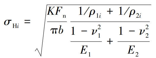
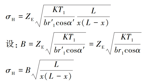
Calculation of Hertzian Stress during Gear Meshing
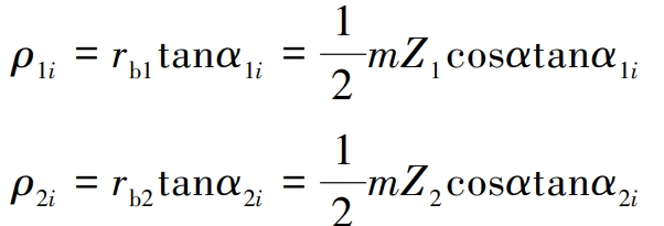
Analyzing the contact stress and maximum contact of the node of the modified gearDifferences in stress, now assuming a pair of offset involute spur gearsTransmission, torque is T1, speed is n1, load correction factor is K, singleThe normal force on the tooth meshing is F n, the tooth width is b, and the tangential force isFt1, modulus m, transmission ratio u, tooth numbers Z1 and Z2, baseThe radii of the circle are rb1 and rb2, and any point on the meshing tooth profile of the two gearsThe radii of the points of contact are COMPARISON OF PRESSURE ANGLE AND RADIUS OF THE POINT OF CONTACTThe radius of the index circle is 販2, the pressure angle of the index circle is α, and the radius of the pitch circle isr′ 1、 f′2, the meshing angle is α′; neglecting the influence of the contact line length b on the coincidence degreeThe impact.
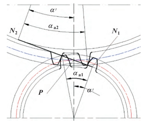
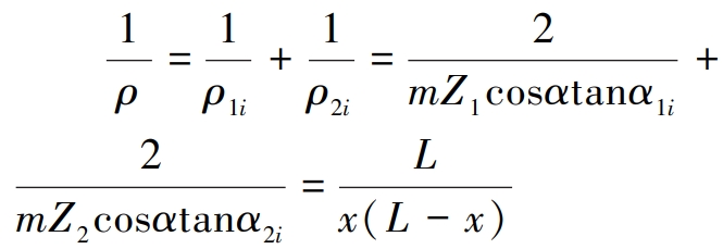
The comprehensive curvature is at the limit meshing near the meshing lineThe point is larger, and the integrated curvature of the midpoint of the limit engagement line has a minimum value.Based on the curvature variation rule, the closer to the end point of the actual meshing line, the higher the contactThe greater the stress, the more likely it is that the actual meshing line will have a double tooth near the end point.In the meshing area, the contact stress is not the maximum, and the contact stress in the single tooth meshing area isTherefore, the maximum contact stress must occur at the limitThe middle point of the meshing line is farther away, close to the limit meshing point of the pinion gear, single tooth meshingThe boundary point between the meshing area and the double-tooth meshing area.
The calculation formula of stress ratio can not only be applied to the design of modified gear transmission,The calculation method can also be applied to standard gear transmission design. The main factors that affect the maximum contact stress areKnown as: number of teeth of the pinion, transmission ratio and meshing angle. In order to analyze stressThe variation law of the ratio is set up with a pair of equidistant modified gear transmissions. When the drivingWhen the number of gear teeth is less than Zmin=17, the formula xmin=h is used∗a ( Zmin -Z1/Zmin to calculate xmin, and select the modification factor x1 of the pinion gear=xmin, then x2= -x1; for equidistantly shifted gear transmission,It indicates that the meshing angle is equal to the pressure angle of the index circle, and the meshing angle has a significant influence on the maximum contact stress.The influence of force does not need to be analyzed separately. Let the number of teeth of the driving gear Z1 beThe range is 10-17, and the transmission ratio is 1.7-6, soThe variation curve of stress ratio relative to the number of teeth of the driving (or small) gear andThe curve of the transmission ratio relative to the change.
When the number of teeth on the pinion gear increases from 10 to 17,The modification factor of the pinion gear gradually decreases, the stress ratio increases, and the maximum contact stressThe stress ratio increases with the increase of the transmission ratio of the equidistantly displaced gear transmission, and the maximum contact stress increases.The line graph indicates that if the transmission ratio is greater than or equal to 3, the number of teeth on the pinion gearWhen it is greater than or equal to 13 (less than 17), the maximum contact stress ratio isThe contact stress is 8% or more.
Non-equidistant modified gear drive (x1when (+ x2 ≥ 0), it can be divided intoPositive transmission and negative transmission. When in positive transmission, the number of teeth of the pinion gear is X1Increase, the stress ratio will increase; while the displacement coefficient x1 increases, the stress ratiowill decrease. Although the variation of the number of teeth of the pinion gear a1 and the modification factor a2 will decrease,The chemical composition will affect the meshing angle and the pressure angle of the pinion tip, but the stress ratioThe comprehensive change rule is the same: as the number of teeth of the pinion gear 诅 increases, the stresswill increase, while the displacement coefficient x1 increases, and the stress ratio will decrease.
Conclusion
Meshing point synthesis of variable involute spur gear transmissionThe calculation formula for the maximum contact stress is derived based on the variation law of the combined curvature,The calculation formula for the ratio of contact stress when it engages with the node is analyzed.The variation law of stress ratio with the number of teeth and transmission ratio of the pinion gear is obtained asConclusions:(1) Obtain the maximum contact stress calculation of the modified gear transmissionThe maximum contact stress can be expressed as the contact stress of node meshingMultiply by the stress ratio, that is: σHma xen = λσHP; derive the calculation of stress ratioand the stress ratio calculation formula was verified using the Abaqus finite element method.The accuracy.(2) Analyzed the variation law of stress ratio. From the deflection gear(Z1<17) The calculation formula of stress ratio shows that the main factors affecting the stress ratio areThe factors are the number of teeth of the pinion and the transmission ratio. When Z1 < 17, the stress ratioAs the number of teeth on the pinion gear increases, the stress ratio increases; similarly, the transmission ratio increases.The stress ratio increases accordingly when the number of teeth on the pinion gear is equal to 17.The calculation formula of stress ratio can be used not only forThe modified involute spur gear is a standard spur gear transmissionThe same applies to movement.(3) If the design criteria for gear contact strength is maximum contactIf the stress ratio is 8% or more higher than the contact stress of the node, it is necessary to adopt the maximum contact stress.The contact stress is accurately designed. Provides the maximum contact stress requiredThe parameter range for force design calculation.