1.Load stroke curve
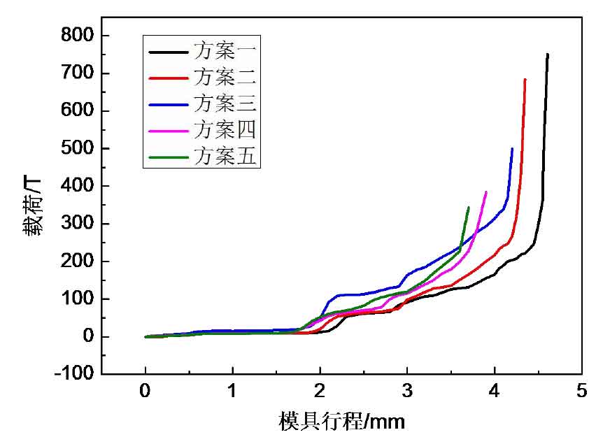
Fig. 1 is the load stroke curve of spiral bevel gear blank obtained according to the approximate trapezoidal tooth profile scheme and different tooth profile heights in the process of closed hot die forging. By observing the curve in the figure, it can be seen that the change trend of the load of each scheme with the die is basically the same: the upper die and the lower die gradually contact the tooth root of the blank with the tooth top of the tooth die, the tooth root of the spiral bevel gear blank is extruded by the tooth die, and the die load increases; The blank metal continuously flows to the tooth top, and the die load increases slowly and tends to be stable; With the increase of the pressing capacity of the die, the blank metal continues to fill the gap area of the toothed model cavity, so that its cross-sectional area gradually shrinks, and the material deformation resistance increases, resulting in a sharp increase in the load.
The forming load of closed hot die forging of spiral bevel gear blank is: scheme I (tooth profile height 4.9mm) reaches about 750t; Scheme II (tooth profile height 5.2mm) reaches about 685t; Scheme III (tooth profile height 5.5mm) reaches about 500t; Scheme 4 (tooth profile height 5.8mm) reaches about 380t; Scheme V (tooth profile height 6.1mm) reaches about 370t. The higher the tooth profile height, the smaller the forming load required. There is a small difference between the forming load values of scheme 4 and scheme 5.
2.Equivalent stress analysis
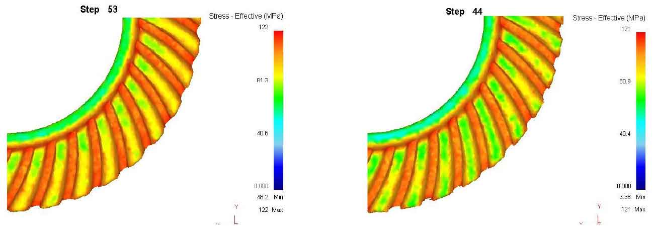
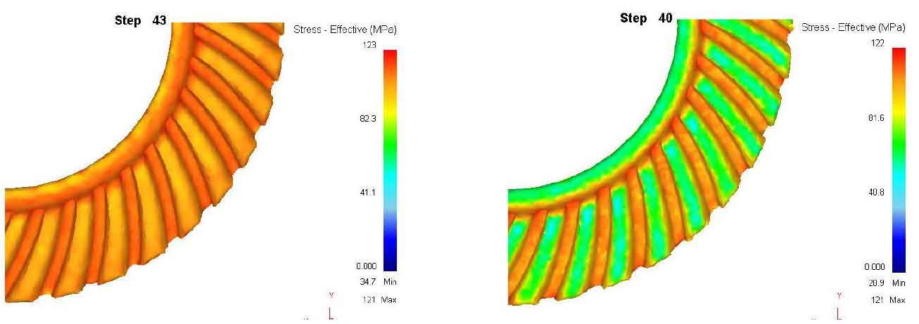
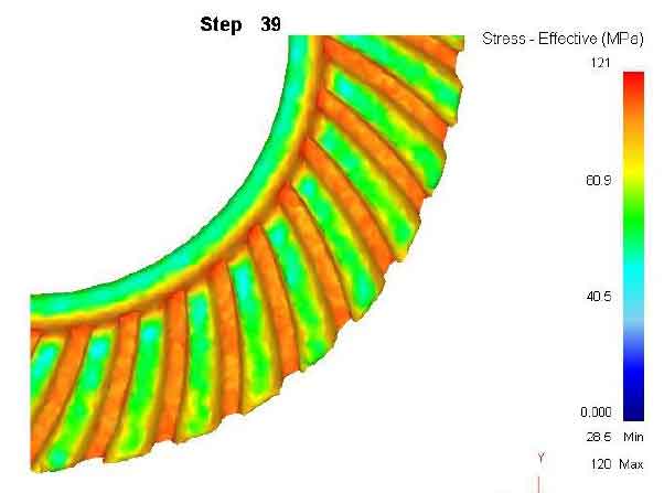
Figure 2 shows the equivalent stress distribution of preforms with different tooth shapes at the end of hot die forging. It is not difficult to see from the analysis of the figure that in each scheme, the equivalent stress at the tooth root of hot die forging preform is very large, reaching about 120MPa, indicating that the extrusion degree of tooth die is the largest. Figure 2 (c) shows that the equivalent stress of the whole tooth surface of the spiral bevel gear blank in scheme 3 is large; The equivalent stress of the spiral bevel gear blank of the other schemes at the tooth top and the inner diameter boss of the spiral bevel gear blank is relatively small.
3.Equivariant analysis
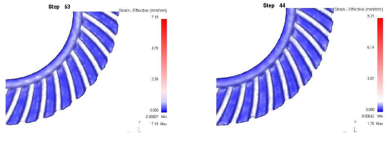
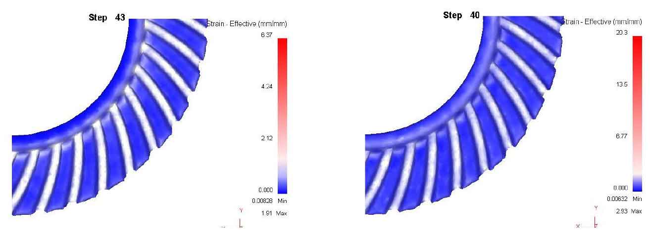
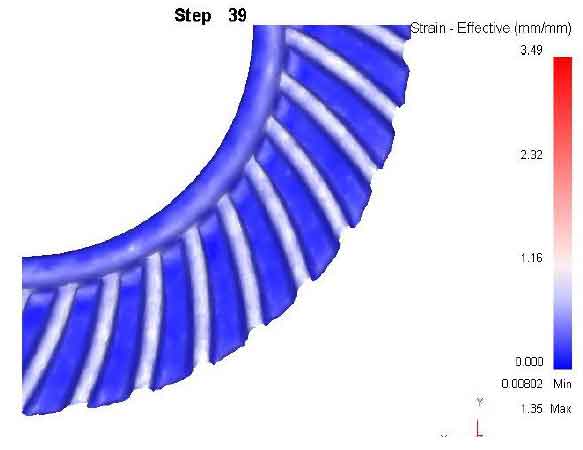
In order to visually display the effect change distribution of spiral bevel gear blank in each scheme, the color display option in the post-processing module is adjusted to ratio, and the results are shown in Figure 3. The maximum equivalent effect variable of each scheme appears at the tooth root of spiral bevel gear blank and the small end and inner diameter boss area of spiral bevel gear blank. The larger the equal effect variable, the better the fluidity of metal materials in the forming process and the higher the product quality. It can be seen from Figure 3 (a) that the maximum equivalent effect variation of scheme 1 reaches 7.18, but figure 2 (a) shows that the equivalent stress value of the whole tooth surface is very large, which will affect the tooth shape forming; Figure 3 (d) shows that the maximum equivalent effect variation of scheme 4 is relatively high, reaching about 2.93, and the stress distribution is ideal. Therefore, in terms of equivalent stress and strain in the forming process, scheme 4 (tooth profile height 5.8mm) is the best scheme.
4.Material flow analysis
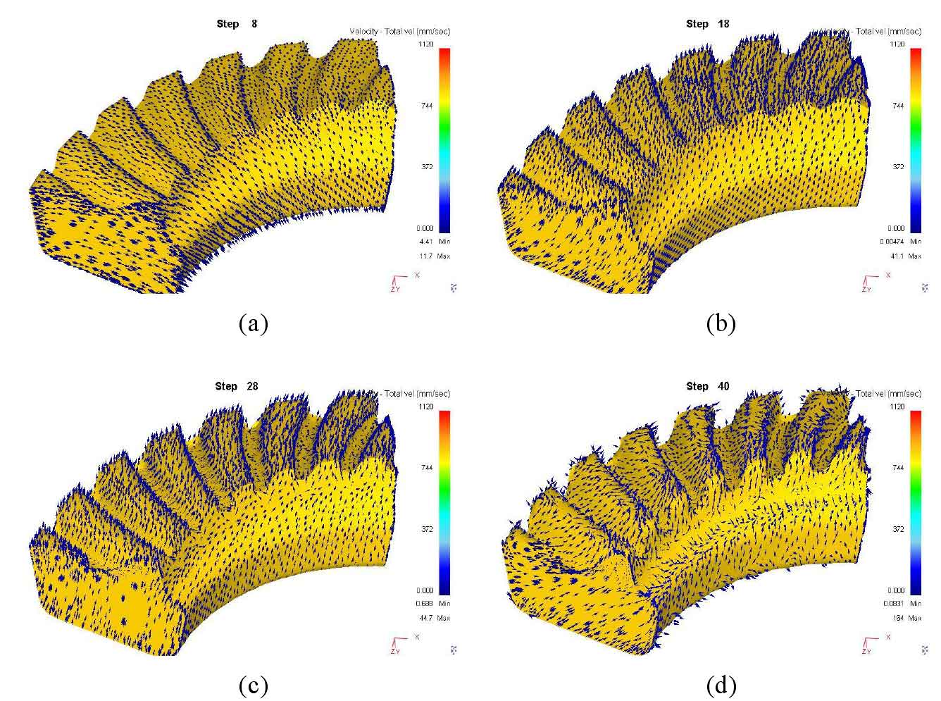
Fig. 4 shows the material flow of tooth blank of scheme 4 (tooth height 5.8mm) in each stage of hot die forging. As shown in the figure, when the upper die starts to contact the spiral bevel gear blank downward, the blank material flows along the radial direction, and the main forming method of the spiral bevel gear blank is thick pier; Then, with the increase of the die stroke, the root of the spiral bevel gear blank begins to be squeezed by the tooth top of the tooth die, resulting in the continuous flow of the blank metal to the gap at the tooth root of the tooth die; When the center of the cavity at the tooth root of the tooth die is gradually filled, the material flow direction turns to fill the corners on both sides of the tooth top and both ends of the tooth shape until the die stroke is completed and the die forging is completed.
Based on the simulation results of the above schemes, it is found that in scheme 4 (tooth height 5.8mm), the forming load is relatively small, the equal effect variation of tooth profile is large, and the stress distribution is ideal; Therefore, it is determined that the hot die forging preform with approximate trapezoidal tooth profile scheme is the best scheme when the tooth profile height is 5.8mm. The tooth shape and size of spiral bevel gear closed hot die forging preform are determined.

