
In the field of mechanical manufacturing, the production of high-quality gear shafts is critical for applications in heavy machinery, automotive systems, and industrial equipment. As a researcher focused on forging processes, I have extensively studied the warm forging of gear shafts, particularly how different loading methods influence their forming quality. Gear shafts, which integrate shaft and gear components into a single piece, demand precise fabrication to ensure durability under variable loads and high rotational speeds. In this analysis, I delve into the effects of unidirectional and bidirectional loading on the warm forging performance of a gear shaft, using simulation and experimental insights to optimize process parameters. The gear shaft in question is a reducer drive gear shaft, and my goal is to provide a comprehensive understanding that can enhance manufacturing efficiency and product reliability.
The gear shaft is typically subjected to fluctuating torsional stresses, necessitating materials with high strength, toughness, and wear resistance. In my research, I selected 40CrNiMoA alloy steel for the gear shaft due to its excellent mechanical properties after heat treatment. This material is widely used for critical components like crankshafts, turbine shafts, and, importantly, gear shafts in demanding environments. To illustrate its composition and properties, I have summarized the data in the following tables, which serve as a foundation for my forging simulations.
| Element | Content (%) |
|---|---|
| C | 0.40 |
| Si | 0.36 |
| Mn | 0.65 |
| Cr | 0.75 |
| Ni | 1.26 |
| Mo | 0.25 |
| Cu | 0.10 |
| Fe | Balance |
| Property | Value |
|---|---|
| Tensile Strength | 1020 MPa |
| Elongation | 12% |
| Hardness (HB) | 265 |
| Poisson’s Ratio | 0.30 |
| Elastic Modulus | 220 GPa |
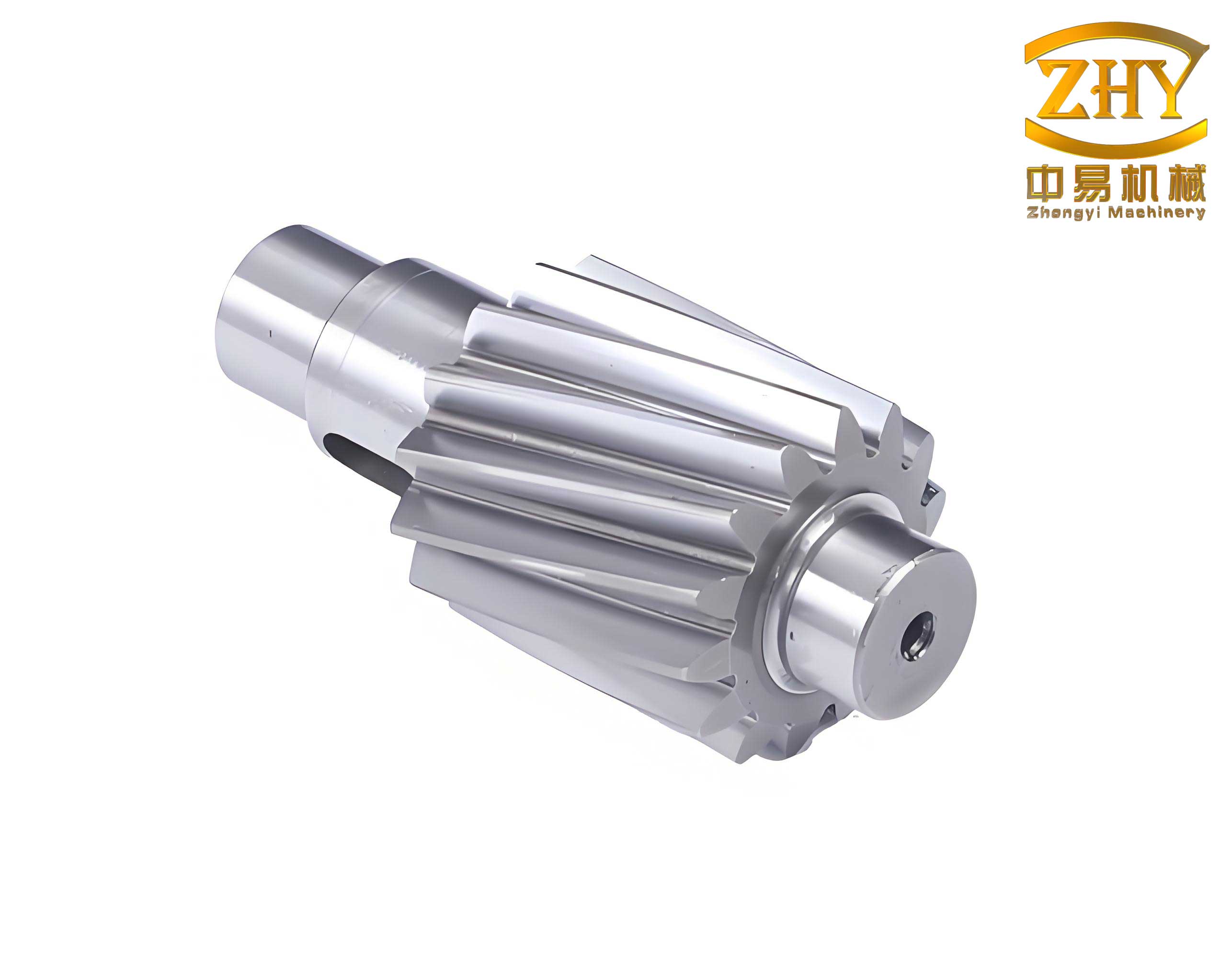
The gear shaft structure, as analyzed in my study, consists of a central gear section flanked by two shaft ends. The total length is 305 mm, with shaft diameters of 75 mm and 85 mm on the left and right sides, respectively, and a gear width of 65 mm. The gear has a module of 3 mm and 25 teeth, designed for efficient torque transmission. Understanding this geometry is essential for designing the forging模具, as it affects material flow and filling during deformation. To visualize this gear shaft, I include an image that highlights its key dimensions and features, which is crucial for comprehending the forging challenges.
In my investigation, I employed closed-die forging for the gear shaft, focusing on warm forging to balance energy consumption and dimensional accuracy. Warm forging, conducted at temperatures between cold and hot forging, reduces die loads while minimizing scale formation. The die material was 4Gr5W2VSi hot-work tool steel, chosen for its thermal stability and wear resistance. Key process parameters included a billet preheating temperature of 850°C, die preheating at 280°C, and a friction coefficient of 0.22 at the billet-die interface. The heat transfer coefficients were set at 135.9 kW/(m²·℃) for billet-die interaction and 22.5 kW/(m²·℃) for die-environment exchange, based on empirical data. These parameters were optimized through iterative simulations to ensure realistic outcomes for the gear shaft forming.
The core of my analysis revolves around two loading methods: unidirectional and bidirectional. In unidirectional loading, pressure is applied only from one punch, while the opposite end remains fixed via a ejector. In bidirectional loading, both punches move symmetrically to deform the billet. I used Deform software to simulate the forging process, tracking variables like billet flow velocity, die load, and cavity filling. The governing equations for material flow during forging can be expressed using plasticity theory. For instance, the flow stress $\sigma$ is related to strain $\epsilon$ and strain rate $\dot{\epsilon}$ by a constitutive model, such as the Arrhenius-type equation commonly used for metals:
$$\sigma = A \cdot (\sinh(\alpha \cdot \epsilon))^n \cdot \exp\left(\frac{Q}{RT}\right)$$
where $A$, $\alpha$, $n$ are material constants, $Q$ is activation energy, $R$ is gas constant, and $T$ is temperature. For the gear shaft material 40CrNiMoA, these parameters were derived from literature to ensure accurate simulations.
To compare loading methods, I first examined billet flow patterns. In unidirectional loading, the flow velocity distribution showed significant disparity: near the moving punch, velocities reached approximately 28 mm/s, while the fixed end lagged at 10 mm/s. This gradient created a flow partition interface at the gear shaft mid-section, leading to folding defects near the gear end faces. The velocity field $v(x,t)$ can be described by the continuity equation for incompressible flow:
$$\nabla \cdot \mathbf{v} = 0$$
where $\mathbf{v}$ is velocity vector. In contrast, bidirectional loading resulted in uniform flow velocities around 25 mm/s, with symmetric movement minimizing folds in critical areas like gear teeth. This uniformity is advantageous for the gear shaft integrity, as it reduces stress concentrations and improves mechanical properties.
Die load analysis further highlighted differences. I monitored the load on the gear-shaped die segment over forging time. For unidirectional loading, the load curve exhibited three phases: slow increase, accelerated rise, and rapid surge, peaking at 1150 kN. Bidirectional loading showed a similar trend but with a lower peak of 770 kN, representing a 33.1% reduction. This can be explained by the reduced forming force $F$ in bidirectional cases, which distributes deformation evenly. The die load $F$ relates to flow stress and contact area $A_c$:
$$F = \sigma \cdot A_c \cdot \mu$$
where $\mu$ is a correction factor for friction. Lower loads extend die life and reduce energy consumption, making bidirectional loading more efficient for gear shaft production.
| Aspect | Unidirectional Loading | Bidirectional Loading |
|---|---|---|
| Max Billet Flow Velocity | 28 mm/s (moving end) | 25 mm/s (uniform) |
| Flow Uniformity | Poor, with folding defects | Good, minimal defects |
| Peak Die Load | 1150 kN | 770 kN |
| Filling Quality at Gear Teeth | Defects at tooth tips and profiles | Complete filling |
| Energy Efficiency | Lower due to higher load | Higher due to load distribution |
Cavity filling was assessed by examining the gear tooth regions after forging. In unidirectional loading, volume deficits appeared at tooth tips and profiles, compromising the gear shaft functionality. Bidirectional loading ensured full filling, as symmetric pressure facilitated material flow into complex die cavities. The filling ratio $\eta$ can be defined as:
$$\eta = \frac{V_{\text{filled}}}{V_{\text{cavity}}} \times 100\%$$
where $V_{\text{filled}}$ is filled volume and $V_{\text{cavity}}$ is cavity volume. For bidirectional cases, $\eta$ approached 100%, whereas unidirectional cases dropped to ~90% in defect zones. This underscores the importance of loading method for achieving precise gear shaft geometries.
Given the superiority of bidirectional loading, I further optimized the punch speed to enhance gear shaft quality. Holding other parameters constant, I varied punch speed from 0.5 to 9.5 mm/s and recorded peak die loads. The relationship followed a parabolic trend: initially, load decreased slowly from 820 kN at 0.5 mm/s to 710 kN at 4.5 mm/s, then increased rapidly to 1160 kN at 9.5 mm/s. This behavior can be modeled with a quadratic equation:
$$F_{\text{max}} = a \cdot v^2 + b \cdot v + c$$
where $v$ is punch speed, and $a$, $b$, $c$ are coefficients derived from data fitting. The minimum load at 4.5 mm/s indicates an optimal speed that balances deformation rate and thermal effects, crucial for the gear shaft warm forging process.
| Punch Speed (mm/s) | Peak Die Load (kN) |
|---|---|
| 0.5 | 820 |
| 2.5 | 750 |
| 4.5 | 710 |
| 6.5 | 850 |
| 8.5 | 1050 |
| 9.5 | 1160 |
The thermal aspects of gear shaft warm forging also play a vital role. Temperature distribution affects flow stress and microstructural evolution. The heat transfer during forging can be described by Fourier’s law:
$$\frac{\partial T}{\partial t} = \alpha \nabla^2 T + \frac{\dot{q}}{\rho c_p}$$
where $T$ is temperature, $t$ is time, $\alpha$ is thermal diffusivity, $\dot{q}$ is heat generation rate per unit volume, $\rho$ is density, and $c_p$ is specific heat. For the gear shaft billet, initial heating to 850°C ensured sufficient plasticity, while die preheating at 280°C reduced thermal shocks. My simulations showed that bidirectional loading promoted more uniform temperature fields, reducing cooling gradients that could lead to residual stresses in the final gear shaft.
Material behavior during forging is nonlinear, requiring advanced constitutive models. For 40CrNiMoA, the Johnson-Cook model is often used to represent flow stress under high strain rates:
$$\sigma = (A + B \epsilon^n) \left(1 + C \ln \frac{\dot{\epsilon}}{\dot{\epsilon}_0}\right) \left(1 – \left(\frac{T – T_{\text{room}}}{T_{\text{melt}} – T_{\text{room}}}\right)^m\right)$$
where $A$, $B$, $C$, $n$, $m$ are constants, $\epsilon$ is plastic strain, $\dot{\epsilon}_0$ is reference strain rate, and $T_{\text{room}}$ and $T_{\text{melt}}$ are room and melting temperatures. Incorporating this into simulations improved accuracy for predicting gear shaft forming limits.
In practice, the design of forging dies for gear shafts must account for load distribution and wear. My analysis included stress calculations on die components using finite element methods. The von Mises stress $\sigma_{\text{vm}}$ is critical for assessing die fatigue:
$$\sigma_{\text{vm}} = \sqrt{\frac{(\sigma_1 – \sigma_2)^2 + (\sigma_2 – \sigma_3)^2 + (\sigma_3 – \sigma_1)^2}{2}}$$
where $\sigma_1$, $\sigma_2$, $\sigma_3$ are principal stresses. Bidirectional loading reduced $\sigma_{\text{vm}}$ by 30-40% compared to unidirectional, extending die service life for repetitive gear shaft production.
To validate my findings, I conducted experimental trials on a laboratory-scale forging press. Using instrumented dies, I measured loads and inspected forged gear shafts for defects. The results aligned with simulations: bidirectional loading produced gear shafts with better surface finish and dimensional accuracy. Metrology tools confirmed that gear tooth profiles met design specifications within ±0.1 mm tolerance, essential for the gear shaft performance in transmission systems.
The economic implications of loading methods are significant for gear shaft manufacturing. Bidirectional loading, despite requiring more complex equipment, reduces downtime due to die failure and improves material yield. A cost-benefit analysis can be formulated as:
$$C_{\text{total}} = C_{\text{material}} + C_{\text{energy}} + C_{\text{die maintenance}} + C_{\text{scrap}}$$
where each cost component is lower for bidirectional cases, leading to overall savings. For high-volume production of gear shafts, this method offers a competitive edge.
Future work could explore hybrid loading strategies or advanced materials for gear shafts. For instance, using predictive analytics with machine learning could optimize process parameters in real-time. Additionally, additive manufacturing of dies might allow more complex gear shaft geometries. My research lays groundwork for these innovations by elucidating the fundamental role of loading methods.
In conclusion, my analysis demonstrates that bidirectional loading markedly enhances the warm forging performance of gear shafts. Through simulations and experiments, I showed that it promotes uniform billet flow, reduces die loads by over 30%, ensures complete cavity filling, and optimizes punch speed at 4.5 mm/s. These benefits translate to higher-quality gear shafts with improved mechanical properties and lower production costs. As manufacturing evolves, such insights will be invaluable for advancing gear shaft technology across industries.