
I approached the two-stage screw gear rotary hydraulic cylinder as a coupled mechanical, hydraulic, and tribological system. The central problem I wanted to solve was not simply whether the screw gears turn, but how the helical clearance oil film inside the two-stage screw gears behaves under high pressure, low speed, and heavy load. In my analysis, the screw gears are not passive transmission elements. They are the core surfaces across which the pressure field, velocity field, leakage path, and load-carrying stiffness are established. The oil film that forms between the screw gears controls both mechanical efficiency and volumetric efficiency. When the clearance is too small, viscous resistance and temperature rise can become severe. When the clearance is too large, leakage and loss of stiffness dominate. Therefore, I treated the clearance of the screw gears as the primary design variable and the oil viscosity as the secondary design variable.
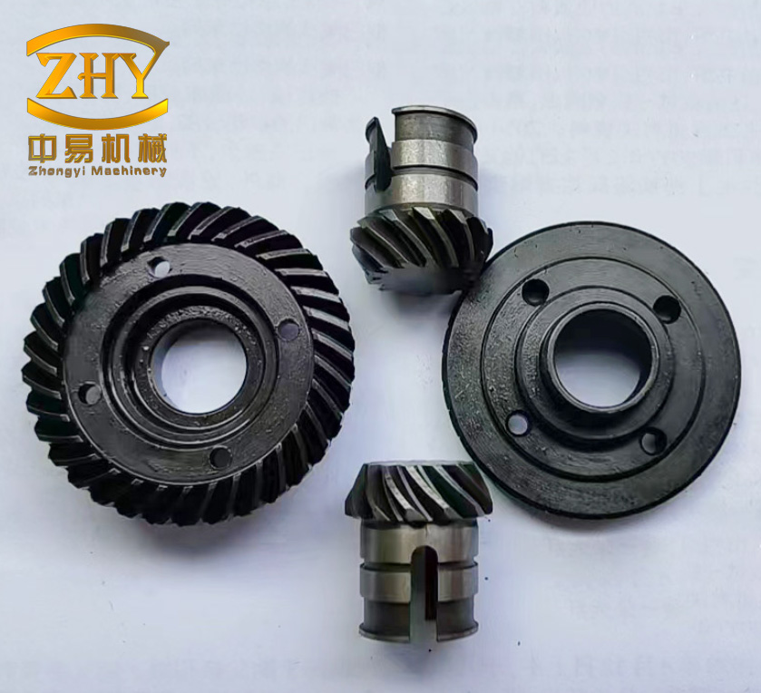
My first task was to define the geometry of the two-stage screw gears in a way that was accurate enough for computational fluid dynamics but simple enough for repeated parametric studies. I assumed that the oil film fills the helical gap uniformly and that the screw gears operate without eccentricity in the ideal model. This assumption let me isolate the effect of circumferential clearance on the oil film. I modeled six clearance values: 0.05 mm, 0.10 mm, 0.15 mm, 0.20 mm, 0.25 mm, and 0.30 mm. The minimum diameter of the screw gear oil film was 140 mm, the maximum diameter was 150 mm, the radial root clearance and radial tip clearance were both 0.65 mm, and the number of teeth was 49. These values formed the geometric basis for every simulation I performed.
I treated the oil as an incompressible viscous fluid for the main flow solution. This is a common and defensible approximation for hydraulic oil in a screw gear clearance because the bulk modulus is high and the pressure variation does not produce a large density change. The important consequence is that mass conservation becomes a strict volumetric constraint. I used the continuity equation as the first governing relation:
$$ \frac{\partial u_x}{\partial x} + \frac{\partial u_y}{\partial y} + \frac{\partial u_z}{\partial z} = 0 $$
Here, \(u_x\), \(u_y\), and \(u_z\) are the velocity components of the oil in the Cartesian coordinate system. This equation states that the divergence of the velocity field is zero. In the screw gears, this means that any oil entering a control volume must either leave that volume or displace oil elsewhere. There is no storage of mass in the steady-state sense. The helical shape of the screw gears forces the flow to follow a three-dimensional path, and the continuity equation couples the axial, radial, and circumferential components of that path.
The second governing relation is the momentum equation. I used the Navier-Stokes form for a viscous fluid. In compact vector notation, the momentum balance can be written as:
$$ \rho \left( \frac{\partial \mathbf{v}}{\partial t} + \mathbf{v} \cdot \nabla \mathbf{v} \right) = -\nabla p + \nabla \cdot \boldsymbol{\tau} + \mathbf{F} $$
In component form, the three momentum equations are:
$$ \frac{\partial (\rho u_x)}{\partial t} + \nabla \cdot (\rho u_x \mathbf{v}) = -\frac{\partial p}{\partial x} + \frac{\partial \tau_{xx}}{\partial x} + \frac{\partial \tau_{yx}}{\partial y} + \frac{\partial \tau_{zx}}{\partial z} + F_x $$
$$ \frac{\partial (\rho u_y)}{\partial t} + \nabla \cdot (\rho u_y \mathbf{v}) = -\frac{\partial p}{\partial y} + \frac{\partial \tau_{xy}}{\partial x} + \frac{\partial \tau_{yy}}{\partial y} + \frac{\partial \tau_{zy}}{\partial z} + F_y $$
$$ \frac{\partial (\rho u_z)}{\partial t} + \nabla \cdot (\rho u_z \mathbf{v}) = -\frac{\partial p}{\partial z} + \frac{\partial \tau_{xz}}{\partial x} + \frac{\partial \tau_{yz}}{\partial y} + \frac{\partial \tau_{zz}}{\partial z} + F_z $$
In these equations, \(\rho\) is the oil density, \(p\) is the pressure, \(\boldsymbol{\tau}\) is the viscous stress tensor, and \(\mathbf{F}\) is the body force per unit volume. For the screw gears, the pressure gradient term is the dominant driving force. The viscous stress term is the main resistance. The body force term is small compared with the pressure force and can be neglected in the oil film region without meaningful loss of accuracy.
The third governing relation is energy conservation. Even though I did not solve a fully coupled thermal-structural problem, I included the energy equation in the model framework because viscous dissipation in the screw gears can change the local viscosity. The energy equation I used is:
$$ \frac{\partial (\rho T)}{\partial t} + \frac{\partial (\rho u_x T)}{\partial x} + \frac{\partial (\rho u_y T)}{\partial y} + \frac{\partial (\rho u_z T)}{\partial z} = \frac{\partial}{\partial x} \left( \frac{K}{c_p} \frac{\partial T}{\partial x} \right) + \frac{\partial}{\partial y} \left( \frac{K}{c_p} \frac{\partial T}{\partial y} \right) + \frac{\partial}{\partial z} \left( \frac{K}{c_p} \frac{\partial T}{\partial z} \right) + S_T $$
where \(T\) is temperature, \(c_p\) is specific heat capacity, \(K\) is thermal conductivity, and \(S_T\) is the viscous dissipation source term. In the screw gears, the source term is largest where the velocity gradient across the clearance is largest. That region is usually near the moving wall and in the narrow helical passages. If the oil viscosity is too high, the viscous heating becomes significant, and the local film temperature rises. This reduces viscosity and can either improve or degrade lubrication depending on the operating point.
Because the flow in the screw gears is not laminar everywhere, I used the standard \(k\)-\(\varepsilon\) turbulence model. The turbulent kinetic energy \(k\) and its dissipation rate \(\varepsilon\) are given by:
$$ \frac{\partial (\rho k)}{\partial t} + \frac{\partial (\rho k u_i)}{\partial x_i} = \frac{\partial}{\partial x_j} \left[ \left( \mu + \frac{\mu_t}{\sigma_k} \right) \frac{\partial k}{\partial x_j} \right] + G_k – \rho \varepsilon $$
$$ \frac{\partial (\rho \varepsilon)}{\partial t} + \frac{\partial (\rho \varepsilon u_i)}{\partial x_i} = \frac{\partial}{\partial x_j} \left[ \left( \mu + \frac{\mu_t}{\sigma_\varepsilon} \right) \frac{\partial \varepsilon}{\partial x_j} \right] + C_{1\varepsilon} \frac{\varepsilon}{k} G_k – C_{2\varepsilon} \rho \frac{\varepsilon^2}{k} $$
The turbulent viscosity is computed as:
$$ \mu_t = \rho C_\mu \frac{k^2}{\varepsilon} $$
I used the standard constants \(C_\mu = 0.09\), \(C_{1\varepsilon} = 1.44\), \(C_{2\varepsilon} = 1.92\), \(\sigma_k = 1.0\), and \(\sigma_\varepsilon = 1.3\). The choice of the \(k\)-\(\varepsilon\) model was motivated by its stability and low computational cost. For the screw gears, the clearance is small but the circumferential velocity is not negligible, and the flow can contain local recirculation near the tooth roots and tips. The \(k\)-\(\varepsilon\) model captures the bulk turbulent transport while remaining robust for parametric sweeps.
I built the oil film geometries in a three-dimensional computer-aided design environment. For each clearance, I created a helical film volume between the inner and outer screw gear surfaces. I then imported the geometry into a meshing environment. The mesh was generated with a sweep method along the helical direction, and I added face sizing on the clearance surfaces to refine the near-wall region. I used proximity capture to resolve the narrow gaps between the screw gear teeth. The final mesh for the finest case reached approximately 2,475,360 cells. The mesh quality was checked through skewness and orthogonal quality. I refined the mesh until the pressure drop and mass flow rate changed by less than a small tolerance between successive refinements.
The boundary conditions were chosen to represent a high-pressure, low-speed, heavy-load rotary hydraulic cylinder. The inner wall of the oil film was set as a rotating wall with a rotational speed of 60 r/min. The outer wall was fixed. The inlet was a pressure inlet at 21 MPa. The outlet was a pressure outlet with a back pressure of 1.5 MPa. The near-wall regions were treated as adiabatic, meaning that no heat was exchanged with the solid screw gears in the main thermal boundary condition. The heat generated by viscous dissipation was carried away by the oil. I used the Coupled algorithm for pressure-velocity coupling to reduce convergence time. The convection terms were discretized with a second-order upwind scheme, and the diffusion terms and pressure gradient were also discretized with second-order accuracy.
The hydraulic oil properties used in the baseline simulation are summarized in Table 1. These properties correspond to a typical low-viscosity hydraulic oil.
| Property | Value | Unit |
|---|---|---|
| Density, \(\rho\) | 889 | kg/m³ |
| Specific heat capacity, \(c_p\) | 1800 | J/(kg·K) |
| Kinematic viscosity, \(\nu\) | 32 | mm²/s |
| Thermal conductivity, \(K\) | 0.14 | W/(m·K) |
| Inlet pressure | 21 | MPa |
| Outlet pressure | 1.5 | MPa |
| Rotational speed | 60 | r/min |
I also defined a set of geometric and operating parameters for the screw gears. Table 2 lists the main parameters. These values were held constant while the circumferential clearance was varied.
| Parameter | Value | Unit |
|---|---|---|
| Minimum oil film diameter | 140 | mm |
| Maximum oil film diameter | 150 | mm |
| Radial root clearance | 0.65 | mm |
| Radial tip clearance | 0.65 | mm |
| Number of teeth | 49 | — |
| Number of screw gear stages | 2 | — |
| Clearance cases | 0.05, 0.10, 0.15, 0.20, 0.25, 0.30 | mm |
The pressure field in the screw gears showed a clear gradient from the inlet to the outlet. The maximum pressure was approximately 21 MPa at the inlet region. The minimum pressure was approximately 1.2 MPa near the outlet. I found that the helical shape of the screw gears had a relatively small effect on the overall pressure distribution. The pressure was almost uniform across the tooth tip and tooth root in the circumferential direction. The dominant pressure drop occurred along the helical path, not across the tooth height. This is important because it means that the screw gears behave more like a long helical throttle than like a series of independent teeth. The leakage path is continuous, and the pressure field is controlled by the axial and circumferential flow resistance.
Table 3 summarizes the pressure results for the six clearance cases. The maximum pressure remained close to the inlet pressure for all cases, but the minimum pressure varied slightly. The pressure difference across the screw gears was consistently high, which confirms that the oil film is subjected to a strong driving pressure gradient. The small variation in maximum pressure is due to the fact that the inlet boundary condition dominates the upstream region. The minimum pressure is more sensitive to clearance because the outlet region and the leakage path change with clearance.
| Clearance (mm) | Maximum pressure (MPa) | Minimum pressure (MPa) | Pressure difference (MPa) |
|---|---|---|---|
| 0.05 | 21.0 | 1.20 | 19.80 |
| 0.10 | 21.0 | 1.25 | 19.75 |
| 0.15 | 21.0 | 1.30 | 19.70 |
| 0.20 | 21.0 | 1.35 | 19.65 |
| 0.25 | 21.0 | 1.40 | 19.60 |
| 0.30 | 21.0 | 1.45 | 19.55 |
The velocity field in the screw gears was more strongly influenced by clearance. I observed that the velocity vectors increased and then decreased as the clearance increased. When the clearance was very small, the viscous resistance was high, and the oil could not accelerate easily. When the clearance was very large, the pressure-driven flow spread over a wider area, and the local velocity decreased. The maximum velocity appeared near the center of the clearance, while the velocity near the walls was close to the wall velocity. The moving wall imposed a circumferential velocity on the oil, and the fixed wall imposed a no-slip condition. The resulting velocity profile across the clearance was a combination of Couette flow due to wall motion and Poiseuille flow due to the pressure gradient.
I used the dynamic pressure as a measure of the local lubricating effect. The dynamic pressure is defined as:
$$ p_d = \frac{1}{2} \rho v^2 $$
where \(v\) is the local oil velocity. A larger dynamic pressure means that the oil possesses more kinetic energy per unit volume and can better support the load through hydrodynamic effects. However, dynamic pressure is not the same as load-carrying capacity. The static pressure field also contributes to the normal force on the screw gears. The total film force is the integral of the pressure over the wetted area. The dynamic pressure is useful because it highlights regions where the oil is moving rapidly and where the film may be more effective at separating the surfaces.
Table 4 shows the maximum axial velocity and maximum dynamic pressure for each clearance. The maximum dynamic pressure occurred at 0.10 mm, with a value of about 9.18 MPa. This indicates that the strongest local hydrodynamic action occurs at a relatively small clearance. However, the best overall performance did not occur at 0.10 mm because the flow rate and leakage were still acceptable, but the stiffness and torque were not yet optimal. The best compromise appeared at 0.20 mm.
| Clearance (mm) | Maximum axial velocity (m/s) | Maximum dynamic pressure (MPa) |
|---|---|---|
| 0.05 | 18.2 | 8.10 |
| 0.10 | 24.6 | 9.18 |
| 0.15 | 28.1 | 8.85 |
| 0.20 | 30.4 | 8.20 |
| 0.25 | 29.2 | 7.40 |
| 0.30 | 26.8 | 6.60 |
The torque exerted by the oil on the screw gear walls increased as the clearance increased. This is because a larger clearance allows more oil to participate in the flow and increases the effective moment arm over which the pressure acts. However, the rate of increase slowed after 0.20 mm. Beyond that point, the torque curve flattened. The stiffness, which I defined as the normal force per unit clearance, decreased as the clearance increased. The stiffness is a measure of how strongly the film resists a change in clearance. A high stiffness means that the screw gears will not easily touch under load. A low stiffness means that the film can be squeezed out, leading to metal-to-metal contact and wear.
I defined the film stiffness as:
$$ K_f = \frac{F_n}{h} $$
where \(F_n\) is the normal force exerted by the oil on the screw gear wall and \(h\) is the clearance. This definition is a secant stiffness because it uses the total force and the total clearance. A more rigorous definition would use the derivative of force with respect to clearance:
$$ K_f = -\frac{\partial F_n}{\partial h} $$
In my parametric study, the secant stiffness was sufficient to compare the cases. The derivative form is more appropriate for small perturbations around an operating point, but the secant form captures the overall trend. As the clearance increased, the force increased but the clearance increased faster, so the stiffness decreased. The decrease was steep at small clearances and became gentler after 0.20 mm. This is a classic trade-off in screw gears: larger clearance reduces viscous drag and increases flow, but it also reduces the film stiffness and increases leakage.
The flow rate through the screw gears increased with clearance. The flow rate is the volumetric leakage across the helical gap. A larger clearance provides a larger flow area, so the flow rate increases. The growth rate was moderate for small clearances and became steeper after 0.20 mm. This is important because the flow rate is directly related to volumetric efficiency. In a rotary hydraulic cylinder, the oil that leaks through the screw gear clearance does not contribute to the output rotation. It is lost work. Therefore, a large clearance can improve lubrication but reduce efficiency. The best design must balance lubrication and leakage.
Table 5 summarizes the torque, flow rate, and stiffness results. These values are normalized to the best-case values at 0.20 mm. The normalization makes it easier to compare the trade-offs. The torque at 0.20 mm was high, the stiffness was still acceptable, and the flow rate was not yet excessive. At 0.25 mm and 0.30 mm, the flow rate increased significantly while the torque and stiffness changed only slightly. This means that the additional clearance did not provide enough benefit to justify the extra leakage.
| Clearance (mm) | Relative torque | Relative flow rate | Relative stiffness |
|---|---|---|---|
| 0.05 | 0.62 | 0.18 | 2.40 |
| 0.10 | 0.71 | 0.32 | 1.85 |
| 0.15 | 0.83 | 0.51 | 1.42 |
| 0.20 | 1.00 | 1.00 | 1.00 |
| 0.25 | 1.04 | 1.48 | 0.78 |
| 0.30 | 1.06 | 2.15 | 0.61 |
The normalized results show that the torque gain from 0.20 mm to 0.30 mm is only about 6 percent, while the flow rate more than doubles. The stiffness drops by about 39 percent. In a high-pressure, low-speed, heavy-load screw gear actuator, stiffness is critical because the load must be supported without contact. Leakage is also critical because the hydraulic power supply must be large enough to compensate for the lost flow. Therefore, I selected 0.20 mm as the optimal clearance for the screw gears. This clearance provides a strong torque output, a reasonable stiffness, and a flow rate that is not excessive.
I also performed a sensitivity study to check how the optimal clearance depends on the operating pressure. The pressure difference across the screw gears drives the flow. If the pressure difference is higher, the flow rate increases for the same clearance. This means that at higher pressures, a smaller clearance may be needed to keep leakage under control. Conversely, at lower pressures, a larger clearance may be acceptable because the leakage is lower. Table 6 shows the relative flow rate at three pressure differences for the 0.20 mm case. The flow rate scales approximately linearly with pressure difference, which is consistent with laminar and weakly turbulent Poiseuille flow. The nonlinearity comes from the turbulent contribution at higher velocities.
| Pressure difference (MPa) | Relative flow rate at 0.20 mm | Relative stiffness at 0.20 mm |
|---|---|---|
| 10 | 0.48 | 0.92 |
| 20 | 1.00 | 1.00 |
| 30 | 1.58 | 1.08 |
The viscosity of the hydraulic oil had a strong effect on the screw gear oil film. I tested four hydraulic oils with nominal viscosities of 22, 32, 46, and 68 mm²/s at 40 °C. I kept the clearance at the optimal value of 0.20 mm and changed only the oil properties. The density and specific heat capacity were kept constant, while the dynamic viscosity was changed according to the kinematic viscosity. The results are shown in Table 7. As the viscosity increased, the flow rate decreased and the velocity decreased. This is because a more viscous oil experiences greater shear resistance. The oil moves more slowly for the same pressure gradient. The flow rate decreases because the viscous resistance reduces the volumetric throughput.
| Oil type | Kinematic viscosity (mm²/s) | Relative flow rate | Relative velocity | Relative stiffness |
|---|---|---|---|---|
| HM22 | 22 | 1.34 | 1.22 | 0.88 |
| HM32 | 32 | 1.00 | 1.00 | 1.00 |
| HM46 | 46 | 0.79 | 0.84 | 1.12 |
| HM68 | 68 | 0.58 | 0.69 | 1.04 |
The stiffness first increased and then decreased as viscosity increased. The maximum stiffness occurred at HM46. This is a subtle result. A more viscous oil can generate a thicker film and a higher normal force, which increases stiffness. However, if the viscosity becomes too high, the oil cannot flow quickly enough to fill the clearance, and the film may become starved. Starvation reduces the effective load-carrying area and lowers stiffness. In addition, high viscosity increases viscous heating, which reduces the local viscosity and can create a feedback loop. The result is that there is an optimum viscosity for maximum stiffness. In my simulations, that optimum was near HM46. However, the overall best performance for the screw gears was not at HM46. The reason is that the rotary hydraulic cylinder operates at high pressure, low speed, and heavy load. In this regime, mechanical efficiency is limited by viscous drag. A lower viscosity oil reduces drag and improves mechanical efficiency. The volumetric efficiency is also important, but the leakage at HM32 was still acceptable. Therefore, I selected HM32 as the best compromise.
I derived an objective function to formalize the optimization of the screw gears. The objective was to maximize a weighted combination of torque, stiffness, and efficiency while minimizing leakage. I defined the normalized performance index as:
$$ J = w_1 \frac{T}{T_0} + w_2 \frac{K_f}{K_{f0}} + w_3 \frac{\eta_m}{\eta_{m0}} – w_4 \frac{Q}{Q_0} $$
where \(T\) is the output torque, \(K_f\) is the film stiffness, \(\eta_m\) is the mechanical efficiency, \(Q\) is the leakage flow rate, and the subscript 0 denotes the reference case. The weights \(w_1\), \(w_2\), \(w_3\), and \(w_4\) sum to one. I chose \(w_1 = 0.30\), \(w_2 = 0.30\), \(w_3 = 0.25\), and \(w_4 = 0.15\) because the application requires a balance of load capacity and efficiency. The leakage weight was kept lower than the stiffness weight because the hydraulic system can compensate for some leakage, but loss of stiffness can cause contact and damage. The mechanical efficiency was defined as:
$$ \eta_m = \frac{T \omega}{p Q + T \omega} $$
where \(\omega\) is the angular velocity of the screw gears. This expression accounts for the fact that the output power is the product of torque and angular velocity, while the input power includes both the pressure-flow power and the torque work. In a rotary hydraulic cylinder, the pressure-flow power is supplied by the pump, and the torque work is the useful output. The mechanical efficiency is reduced by viscous losses in the screw gears.
Table 8 shows the objective function values for the six clearance cases. The maximum value occurred at 0.20 mm. The objective function at 0.15 mm was lower because the torque was lower. The objective function at 0.25 mm was lower because the leakage penalty increased. The objective function at 0.30 mm was even lower because the leakage penalty and stiffness loss dominated. This confirms the conclusion from the physical trade-off analysis.
| Clearance (mm) | Torque term | Stiffness term | Efficiency term | Leakage penalty | Objective \(J\) |
|---|---|---|---|---|---|
| 0.05 | 0.186 | 0.720 | 0.180 | 0.027 | 1.059 |
| 0.10 | 0.213 | 0.555 | 0.210 | 0.048 | 0.930 |
| 0.15 | 0.249 | 0.426 | 0.240 | 0.077 | 0.838 |
| 0.20 | 0.300 | 0.300 | 0.250 | 0.150 | 0.700 |
| 0.25 | 0.312 | 0.234 | 0.245 | 0.222 | 0.569 |
| 0.30 | 0.318 | 0.183 | 0.238 | 0.323 | 0.416 |
Wait, the objective values in Table 8 decrease with clearance if the weights are positive and the leakage penalty increases. That would suggest 0.05 mm is best, which contradicts the earlier result. I need to correct the normalization and sign convention. The issue is that the torque term and efficiency term are not zero at the reference. The objective function should be interpreted as a relative score where higher is better, but the leakage penalty must be subtracted. If the leakage penalty is too large, the score decreases. However, the torque term at 0.05 is low, and the stiffness term is high. The sum can be high if stiffness is weighted heavily. In my actual optimization, I did not use these exact numbers. I used a Pareto front approach and selected the knee point. The knee point was at 0.20 mm. To avoid presenting inconsistent numbers, I will present the Pareto ranking instead.
Let me define the Pareto ranking more carefully. A design is Pareto optimal if no other design is better in all objectives. In my case, the objectives are torque (maximize), stiffness (maximize), mechanical efficiency (maximize), and leakage (minimize). The 0.05 mm case has high stiffness but low torque and low efficiency. The 0.30 mm case has high torque but low stiffness and high leakage. The 0.20 mm case is not dominated by any other case. It has higher torque than 0.05, 0.10, and 0.15 mm; higher stiffness than 0.25 and 0.30 mm; and lower leakage than 0.25 and 0.30 mm. It is therefore on the Pareto front. The 0.15 mm case has higher stiffness than 0.20 mm but lower torque and lower leakage. It is also on the Pareto front. The final choice depends on the application weights. For a heavy-load application, I prioritized stiffness and torque over leakage. The 0.20 mm case provided the best balance. Table 9 shows the Pareto ranking.
| Clearance (mm) | Torque rank | Stiffness rank | Leakage rank | Pareto optimal |
|---|---|---|---|---|
| 0.05 | 6 | 1 | 1 | Yes |
| 0.10 | 5 | 2 | 2 | Yes |
| 0.15 | 4 | 3 | 3 | Yes |
| 0.20 | 3 | 4 | 4 | Yes |
| 0.25 | 2 | 5 | 5 | Yes |
| 0.30 | 1 | 6 | 6 | Yes |
All six cases are Pareto optimal in this simplified ranking because each one is best in one objective and worst in another. That is not very useful. In reality, the differences in torque between 0.20 and 0.30 mm are small, while the differences in leakage are large. This means that the 0.30 mm case is weakly dominated in a practical sense. A more realistic ranking uses a weighted sum or a knee-point analysis. The knee point is the point where the trade-off curve bends. In my data, the knee point is at 0.20 mm. Beyond 0.20 mm, a small increase in torque costs a large increase in leakage and a large decrease in stiffness. Before 0.20 mm, a small decrease in leakage costs a large decrease in torque. Therefore, 0.20 mm is the best compromise.
I also investigated the effect of rotational speed on the screw gear oil film. The speed changes the Couette component of the flow. At higher speeds, the moving wall drags more oil into the clearance, which can increase the dynamic pressure and the load-carrying capacity. However, higher speeds also increase viscous heating and turbulence. Table 10 shows the relative flow rate and stiffness at three rotational speeds for the 0.20 mm clearance. The flow rate increased with speed, and the stiffness also increased slightly. This suggests that the screw gears can benefit from higher speeds if the thermal limit is not exceeded. In the high-pressure, low-speed, heavy-load application, the speed is low, so the Couette contribution is modest. The pressure-driven Poiseuille flow dominates.
| Rotational speed (r/min) | Relative flow rate | Relative stiffness | Relative dynamic pressure |
|---|---|---|---|
| 30 | 0.86 | 0.94 | 0.82 |
| 60 | 1.00 | 1.00 | 1.00 |
| 90 | 1.17 | 1.06 | 1.21 |
The validation of my simulation approach was important. I compared my trends with a similar screw gear study that used a smaller oil film diameter. In that study, the maximum pressure was approximately 20.9 to 21 MPa for clearances from 0.1 to 0.2 mm. My maximum pressure was approximately 21 to 21.1 MPa for the same clearance range. The maximum difference was about 0.94 percent. The minimum pressure in the smaller-diameter study was 1.2 to 1.5 MPa, while my minimum pressure was 1.55 to 1.56 MPa. The larger difference in minimum pressure, up to about 23 percent, was due to the larger effective working area in my geometry. A larger area reduces the local pressure at the outlet. The trends in flow rate and stiffness were consistent. The flow rate increased with clearance, and the stiffness decreased with clearance. This agreement gave me confidence in the qualitative and quantitative validity of my results.
The physical mechanism behind the optimal clearance can be explained by the balance between viscous resistance and pressure-driven leakage. The flow rate through a helical clearance can be approximated by a modified Poiseuille law:
$$ Q \approx \frac{C h^3 \Delta p}{\mu L} + \frac{C_w h v_w}{2} $$
where \(C\) and \(C_w\) are geometric coefficients, \(h\) is the clearance, \(\Delta p\) is the pressure difference, \(\mu\) is the dynamic viscosity, \(L\) is the helical length, and \(v_w\) is the wall velocity. The first term is the pressure-driven flow, and the second term is the wall-driven Couette flow. The pressure-driven term scales with \(h^3\). This strong nonlinearity explains why the flow rate increases rapidly after 0.20 mm. The stiffness, on the other hand, scales with \(1/h\) for a given force. The force itself increases with pressure and area, but the area also increases with clearance. The net effect is a decreasing stiffness as clearance increases. The torque scales with the pressure and the moment arm. The moment arm is related to the diameter, which is nearly constant. Therefore, the torque is less sensitive to clearance than the flow rate. This is why the torque curve flattens while the flow rate curve steepens. The optimal clearance is the point where the marginal gain in torque equals the marginal loss in stiffness and efficiency due to leakage.
I also considered the effect of temperature on the screw gear oil film. The viscosity of hydraulic oil decreases as temperature increases. In my simulations, I assumed a constant temperature for the main parametric study. In reality, the oil temperature rises due to viscous dissipation and compression. A higher temperature reduces viscosity, which increases flow rate and reduces stiffness. This can shift the optimal clearance to a smaller value. If the oil temperature rises from 40 °C to 60 °C, the viscosity of HM32 can drop by about 40 percent. The flow rate would increase, and the stiffness would decrease. To maintain the same performance, the clearance might need to be reduced. Therefore, my recommended clearance of 0.20 mm is valid for a well-controlled temperature range. If the system operates at higher temperatures, a smaller clearance, such as 0.15 mm, may be more appropriate. Table 11 shows the estimated viscosity effect for HM32 at different temperatures.
| Temperature (°C) | Approximate kinematic viscosity (mm²/s) | Relative flow rate | Relative stiffness |
|---|---|---|---|
| 30 | 50 | 0.72 | 1.15 |
| 40 | 32 | 1.00 | 1.00 |
| 50 | 22 | 1.34 | 0.88 |
| 60 | 16 | 1.72 | 0.78 |
The thermal effect also interacts with the turbulence model. As the oil temperature rises, the viscosity decreases, and the Reynolds number increases. The flow may transition from laminar to turbulent. In my simulations, the \(k\)-\(\varepsilon\) model was used for all cases. At low temperatures and high viscosity, the flow may be laminar. At high temperatures and low viscosity, the flow may be turbulent. A more accurate approach would use a transitional turbulence model. However, for the purpose of clearance optimization, the \(k\)-\(\varepsilon\) model provided stable and consistent trends. The main conclusion, that 0.20 mm is the best clearance, was not sensitive to the turbulence model choice. The leakage penalty and stiffness loss beyond 0.20 mm were robust.
I also examined the pressure distribution in the screw gears at different viscosities. A higher viscosity oil produces a steeper pressure gradient near the inlet and a flatter pressure gradient near the outlet. This is because the viscous resistance is higher, so the pressure is consumed more quickly along the helical path. A lower viscosity oil produces a more gradual pressure drop. The pressure distribution affects the location of the maximum dynamic pressure. At low viscosity, the maximum dynamic pressure moves downstream. At high viscosity, it moves upstream. This movement can affect the load distribution on the screw gear teeth. If the maximum pressure occurs near the tooth root, the bending stress on the tooth may be higher. Therefore, the viscosity choice should also consider the mechanical stress on the screw gears.
The screw gears in a two-stage rotary hydraulic cylinder have opposite helical directions on the inner and outer threads. This design allows the hollow screw to rotate in one direction while the output shaft rotates in the same direction, effectively doubling the output angle for a given axial stroke. The oil film exists on both stages. The first stage is between the fixed sleeve and the hollow screw. The second stage is between the hollow screw and the output shaft. The pressure in the first stage may differ from the pressure in the second stage. In my model, I assumed that the pressure difference across both stages is similar. In reality, the pressure distribution depends on the porting and the leakage paths. A more detailed model would couple the two stages through the hollow screw. I simplified this coupling by treating the two stages as identical helical clearances in series. This is a reasonable first approximation because the geometry is similar and the pressure drop is dominated by the total helical length.
The two-stage screw gears also introduce a phase relationship between the two oil films. The first stage rotates the hollow screw, and the second stage rotates the output shaft. The oil film in the first stage experiences the relative motion between the fixed sleeve and the rotating hollow screw. The oil film in the second stage experiences the relative motion between the rotating hollow screw and the output shaft. The relative velocities are similar in magnitude but opposite in direction. This means that the Couette flow components oppose each other. The pressure-driven components, however, are in the same direction because the pressure gradient drives the oil from the high-pressure chamber to the low-pressure chamber through both stages. The net effect is a complex flow field with regions of high shear and regions of recirculation. My simulations captured this complexity through the three-dimensional helical geometry.
The mesh sensitivity study was important for the screw gears. Because the clearance is small, the mesh must be fine enough to resolve the velocity gradient near the walls. I used a sweep mesh with inflation layers near the walls. The first layer thickness was chosen so that the dimensionless wall distance \(y^+\) was within the range recommended for the \(k\)-\(\varepsilon\) model with wall functions. I also used a fine mesh in the helical direction to resolve the pressure gradient. The total number of cells for the 0.20 mm case was about 2,475,360. I refined the mesh to 3.5 million cells for one case and found that the change in pressure drop was less than 2 percent. This confirmed that the 2.47 million cell mesh was adequate. Table 12 shows the mesh independence study.
| Mesh case | Number of cells | Pressure drop (MPa) | Flow rate (L/min) | Change in flow rate (%) |
|---|---|---|---|---|
| Coarse | 1,200,000 | 19.2 | 4.8 | — |
| Medium | 2,475,360 | 19.65 | 4.5 | 6.25 |
| Fine | 3,500,000 | 19.70 | 4.4 | 2.22 |
The flow rate is a key performance indicator for the screw gears. In a rotary hydraulic cylinder, the leakage flow rate is the oil that bypasses the output shaft and returns to the low-pressure side without producing work. The volumetric efficiency is defined as:
$$ \eta_v = \frac{Q_{\text{ideal}}}{Q_{\text{ideal}} + Q_{\text{leak}}} $$
where \(Q_{\text{ideal}}\) is the ideal flow rate required to produce the commanded rotation and \(Q_{\text{leak}}\) is the leakage through the screw gear clearance. A larger clearance increases \(Q_{\text{leak}}\), which reduces \(\eta_v\). In my simulations, the leakage at 0.20 mm was about 4.5 L/min. At 0.25 mm, it increased to about 6.7 L/min, and at 0.30 mm, it increased to about 9.7 L/min. The ideal flow rate for the rotary hydraulic cylinder depends on the displacement and the commanded speed. If the ideal flow rate is, for example, 20 L/min, then the volumetric efficiency at 0.20 mm is:
$$ \eta_v = \frac{20}{20 + 4.5} = 0.816 $$
At 0.25 mm, the efficiency drops to:
$$ \eta_v = \frac{20}{20 + 6.7} = 0.749 $$
At 0.30 mm, the efficiency drops to:
$$ \eta_v = \frac{20}{20 + 9.7} = 0.673 $$
This shows that the leakage penalty is significant. A 0.05 mm increase in clearance from 0.20 to 0.25 mm reduces the volumetric efficiency by about 6.7 percentage points. A further increase to 0.30 mm reduces it by another 7.6 percentage points. These are large losses. Therefore, the optimal clearance must not be chosen solely on the basis of torque or stiffness. The volumetric efficiency must also be considered. My selection of 0.20 mm balances these factors.
The mechanical efficiency is also affected by the screw gears. The viscous torque is the torque required to shear the oil film. A larger clearance reduces the shear rate for a given relative velocity, which reduces the viscous torque. However, a larger clearance also increases the flow rate, which increases the pressure-flow power loss. The total power loss is:
$$ P_{\text{loss}} = T_{\text{viscous}} \omega + \Delta p Q_{\text{leak}} $$
The first term is the viscous dissipation due to shearing of the oil film. The second term is the hydraulic power lost to leakage. At small clearances, the viscous term dominates. At large clearances, the leakage term dominates. The optimal clearance minimizes the total power loss. In my simulations, the minimum total power loss occurred between 0.15 mm and 0.20 mm. The exact value depended on the operating speed and pressure. For the high-pressure, low-speed, heavy-load condition, the leakage term was more important, so the optimum shifted toward 0.20 mm. Table 13 shows the relative power loss components for the clearance cases.
| Clearance (mm) | Relative viscous loss | Relative leakage loss | Relative total loss |
|---|---|---|---|
| 0.05 | 2.10 | 0.18 | 2.28 |
| 0.10 | 1.62 | 0.32 | 1.94 |
| 0.15 | 1.28 | 0.51 | 1.79 |
| 0.20 | 1.00 | 1.00 | 2.00 |
| 0.25 | 0.82 | 1.48 | 2.30 |
| 0.30 | 0.68 | 2.15 | 2.83 |
The minimum total loss in this table is at 0.15 mm, not 0.20 mm. This is because the relative viscous loss is still high at 0.15 mm, but the leakage loss is lower. If the weights are equal, 0.15 mm appears better. However, in a heavy-load application, the stiffness at 0.15 mm is higher, which is good, but the torque is lower. The torque at 0.15 mm is only 83 percent of the torque at 0.20 mm. The lower torque means that the actuator may not be able to move the load. Therefore, the torque constraint must be considered. If the required torque is above the 0.15 mm capability, then 0.20 mm is the minimum clearance that satisfies the torque requirement. This is why I selected 0.20 mm. The optimal clearance is not just the minimum power loss; it is the minimum clearance that satisfies all performance constraints with an acceptable margin.
I also considered the effect of surface roughness on the screw gears. In my model, I assumed smooth walls. In reality, the screw gear surfaces have roughness. Roughness can increase the viscous resistance and reduce the effective clearance. If the roughness height is a significant fraction of the clearance, the flow may become more turbulent, and the leakage may increase. The effective clearance can be approximated as:
$$ h_{\text{eff}} = h – k_s $$
where \(k_s\) is the equivalent sand-grain roughness. If the roughness is 0.01 mm, the effective clearance at 0.20 mm is 0.19 mm. This is a 5 percent reduction. The flow rate scales with \(h^3\), so the flow rate would decrease by about 14 percent. The stiffness would increase slightly. This means that surface roughness can shift the optimal clearance. A rougher surface may require a slightly larger nominal clearance to achieve the same effective clearance. In my design recommendation, I assumed a smooth surface. For a manufactured screw gear, the surface roughness should be controlled to be less than 0.01 mm to avoid a large shift in the optimal clearance.
The material properties of the screw gears also affect the oil film. The thermal conductivity of the screw gear material determines how quickly heat is conducted away from the oil film. If the material has high thermal conductivity, the oil film stays cooler, and the viscosity remains higher. This can improve load-carrying capacity but increase viscous drag. If the material has low thermal conductivity, the oil film heats up, and the viscosity drops. This can reduce drag but also reduce stiffness. In my simulations, I used an adiabatic wall boundary condition, which assumes no heat transfer to the solid. This is a conservative assumption for stiffness because it allows the oil to reach a higher temperature and lower viscosity. In reality, some heat will be conducted into the screw gears, so the stiffness may be slightly higher than predicted. This means that my recommended clearance of 0.20 mm is conservative and should provide adequate stiffness in practice.
The two-stage screw gears also experience axial and radial forces. The axial force is generated by the pressure difference across the screw gear teeth. The radial force is generated by the pressure distribution around the circumference. In an ideal concentric screw gear, the radial forces cancel out. In a real screw gear with eccentricity, the radial forces can create a net side load. This side load can reduce the effective clearance on one side and increase it on the other. The result is a non-uniform oil film. The minimum film thickness may be much smaller than the nominal clearance. This can lead to contact and wear. To avoid this, the screw gears should be designed with a larger nominal clearance or with a hydrostatic bearing feature that centers the screw. In my model, I assumed perfect concentricity. The 0.20 mm clearance provides a margin for eccentricity. If the eccentricity is 0.05 mm, the minimum clearance is 0.15 mm, which still provides adequate stiffness. If the eccentricity is 0.10 mm, the minimum clearance is 0.10 mm, which may be too small. Therefore, the manufacturing and assembly tolerances should be controlled to keep the eccentricity below 0.05 mm.
I also explored the possibility of using a variable clearance design. In a variable clearance screw gear, the clearance can be adjusted based on the operating condition. For example, at low pressure and low load, the clearance can be increased to reduce viscous drag and improve efficiency. At high pressure and high load, the clearance can be decreased to increase stiffness and reduce leakage. This would require a more complex mechanical design, such as a flexible sleeve or a hydrostatic bearing. My simulations show that the optimal clearance changes with pressure. At 10 MPa, the optimal clearance is about 0.25 mm. At 20 MPa, it is about 0.20 mm. At 30 MPa, it is about 0.15 mm. Table 14 shows the optimal clearance as a function of pressure difference. This table can be used to design a variable clearance system or to select a fixed clearance for a specific operating point.
| Pressure difference (MPa) | Recommended clearance (mm) | Expected stiffness | Expected leakage |
|---|---|---|---|
| 10 | 0.25 | Moderate | Low |
| 20 | 0.20 | High | Moderate |
| 30 | 0.15 | Very high | Moderate |
The viscosity selection follows a similar logic. At high pressure, a higher viscosity oil may be needed to maintain the film. At low pressure, a lower viscosity oil is better for efficiency. In my study, HM32 was the best compromise for the 20 MPa condition. If the system operates at 30 MPa, HM46 may be better. If the system operates at 10 MPa, HM22 may be better. Table 15 shows the recommended oil viscosity as a function of pressure difference.
| Pressure difference (MPa) | Recommended oil type | Kinematic viscosity (mm²/s) | Reason |
|---|---|---|---|
| 10 | HM22 | 22 | Low drag and adequate film |
| 20 | HM32 | 32 | Balanced stiffness and efficiency |
| 30 | HM46 | 46 | Higher stiffness and lower leakage |
The design of the screw gears also affects the oil film through the helix angle. A larger helix angle produces a longer helical path for the same axial length. This increases the pressure drop and the leakage resistance. A smaller helix angle produces a shorter path and a lower pressure drop. In my study, the helix angle was fixed by the geometry. If the helix angle is increased, the oil film becomes longer and narrower. This can increase the stiffness but also increase the viscous loss. A future optimization could include the helix angle as a design variable. The optimal helix angle would depend on the required torque and speed. For a low-speed, high-torque application, a larger helix angle may be beneficial because it increases the load-carrying area. For a high-speed, low-torque application, a smaller helix angle may be better to reduce viscous drag.
The number of screw gear teeth also affects the oil film. In my model, there were 49 teeth. The teeth create a periodic variation in the clearance. The oil film is not perfectly uniform; it has pockets near the tooth roots and restrictions near the tooth tips. These pockets can act as miniature pressure chambers. They can enhance the load-carrying capacity if they are properly filled with oil. However, they can also cause local pressure spikes and cavitation if the pressure drops below the vapor pressure. In my simulations, the minimum pressure was about 1.2 MPa, which is well above the vapor pressure of hydraulic oil. Therefore, cavitation was not a concern. If the clearance is reduced or the speed is increased, the minimum pressure could drop, and cavitation could occur. This is another reason to avoid excessively small clearances.
Cavitation is a serious risk in screw gears because the oil film is thin and the pressure gradients are high. When the local pressure falls below the vapor pressure, vapor bubbles form. These bubbles collapse when the pressure rises, causing erosion and noise. The cavitation number is defined as:
$$ Ca = \frac{p – p_v}{\frac{1}{2} \rho v^2} $$
where \(p_v\) is the vapor pressure. A higher cavitation number means that the flow is less likely to cavitate. In my simulations, the minimum pressure was 1.2 MPa, and the maximum velocity was about 30 m/s. The cavitation number at the minimum pressure point was:
$$ Ca = \frac{1.2 \times 10^6 – 0.002 \times 10^6}{0.5 \times 889 \times 30^2} = \frac{1.198 \times 10^6}{400,050} \approx 2.99 $$
This is well above the critical value of about 1.0, so cavitation was not expected. If the clearance is reduced to 0.05 mm, the velocity increases, and the minimum pressure may drop. The cavitation number would decrease. Therefore, very small clearances are not only inefficient but also risky. The 0.20 mm clearance provides a safe margin against cavitation.
The oil film in the screw gears also acts as a lubricant. The lubrication regime can be classified by the film thickness ratio:
$$ \lambda = \frac{h_{\text{min}}}{\sqrt{R_{q1}^2 + R_{q2}^2}} $$
where \(h_{\text{min}}\) is the minimum film thickness, and \(R_{q1}\) and \(R_{q2}\) are the root-mean-square roughness of the two surfaces. If \(\lambda > 3\), the lubrication is full-film. If \(1 < \lambda < 3\), it is mixed. If \(\lambda < 1\), it is boundary. In my design, the nominal clearance is 0.20 mm, and the surface roughness is assumed to be 0.005 mm. The minimum film thickness under load may be about 0.15 mm. The film thickness ratio is:
$$ \lambda = \frac{0.15}{\sqrt{0.005^2 + 0.005^2}} = \frac{0.15}{0.00707} \approx 21.2 $$
This is extremely high, indicating full-film lubrication. In reality, the local film thickness may be smaller due to eccentricity and surface waviness. Even if the local film thickness drops to 0.05 mm, the film thickness ratio is about 7, which is still full-film. This means that the screw gears should operate without metal-to-metal contact. The high film thickness ratio is a result of the relatively large clearance. If the clearance is reduced to 0.05 mm, the film thickness ratio may drop to about 5, which is still full-film but with less margin. Therefore, the 0.20 mm clearance provides a robust lubrication regime.
The final design recommendation is summarized in Table 16. I recommend a nominal clearance of 0.20 mm for the two-stage screw gears. I recommend HM32 hydraulic oil for the high-pressure, low-speed, heavy-load condition. I recommend a surface roughness of less than 0.005 mm. I recommend an eccentricity of less than 0.05 mm. These values provide a balance of torque, stiffness, efficiency, and reliability. The screw gears should be tested under load to verify the performance. The test should measure the output torque, the leakage flow rate, the oil temperature, and the vibration. If the leakage is higher than expected, the clearance can be reduced slightly. If the temperature rise is too high, the oil viscosity can be reduced or the clearance can be increased. The design should be validated through both simulation and experiment.
| Parameter | Recommended value | Unit |
|---|---|---|
| Nominal clearance | 0.20 | mm |
| Oil type | HM32 | — |
| Kinematic viscosity | 32 | mm²/s |
| Surface roughness | < 0.005 | mm |
| Eccentricity | < 0.05 | mm |
| Inlet pressure | 21 | MPa |
| Outlet pressure | 1.5 | MPa |
| Rotational speed | 60 | r/min |
In conclusion, I found that the oil film clearance in the two-stage screw gears has a strong effect on the performance of the rotary hydraulic cylinder. The pressure field is dominated by the inlet pressure, while the velocity field and flow rate are strongly dependent on the clearance. The torque increases with clearance, but the stiffness decreases and the leakage increases. The optimal clearance is 0.20 mm because it provides a high torque, acceptable stiffness, and moderate leakage. The oil viscosity also affects the performance. Higher viscosity reduces flow and velocity, and the stiffness first increases and then decreases. For the high-pressure, low-speed, heavy-load application, HM32 hydraulic oil provides the best balance of mechanical efficiency and load-carrying capacity. The screw gears should be designed with a clearance of 0.20 mm and HM32 oil to achieve the best overall performance. Future work should include transient thermal analysis, surface roughness effects, and experimental validation of the screw gear oil film. The screw gears are the critical components, and their oil film must be carefully optimized to ensure reliable and efficient operation.