
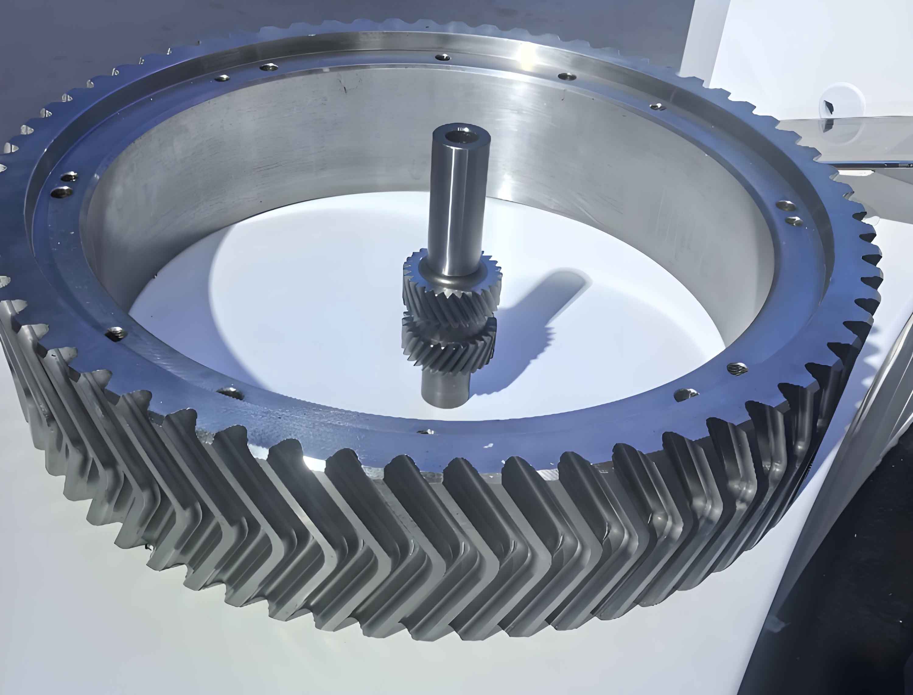
In modern mechanical transmission systems, herringbone gears are widely used due to their high load-carrying capacity and smooth operation. Specifically, double circular arc herringbone gears offer enhanced strength and reliability, making them ideal for demanding applications such as petroleum industry equipment. However, challenges like noise reduction and increased承载能力 persist. In this context, I explore the concept of “staggered teeth” in double circular arc herringbone gears, which involves axially offsetting the left and right tooth faces by half the axial pitch. This innovation aims to improve meshing performance by altering the contact patterns between convex and concave tooth profiles. Throughout this analysis, I will delve into the meshing mechanisms, derive key coefficients, and compare traditional herringbone gears with staggered-tooth variants. The term “herringbone gears” will be emphasized repeatedly to underscore their significance in this study.
The fundamental principle of double circular arc gears lies in their tooth profile, which consists of convex and concave arcs. For herringbone gears, the left and right tooth faces are typically symmetric, leading to simultaneous contact of similar profiles. By introducing staggered teeth, I achieve a configuration where convex teeth on one side oppose concave teeth on the other, thereby optimizing load distribution. This approach requires a detailed understanding of the meshing process. I begin by describing the axial movement of contact points along the gear width. Let the axial pitch be denoted as \( P_x \), calculated as \( P_x = \pi m_n / \sin \beta \), where \( m_n \) is the normal module and \( \beta \) is the helix angle. The contact points shift axially during operation, and their interactions can be visualized using graphical methods.
The meshing analysis involves tracking contact points from the front to the rear end of the gear. For a double circular arc herringbone gear, each tooth has two contact points: one on the convex side and one on the concave side. The axial distance between these points on the same tooth is given by \( q_{s} \), derived from geometric parameters. According to the reference, the formula is:
$$ q_{s} = \left[ \frac{\pi}{2} – 0.5j^* + 4\rho_{a}^* + 2x_1^* \cot \alpha \sin \beta – 2(\rho_{a}^* + x_1^*) \sin \alpha \cos \alpha \sin \beta \right] \cdot m_n $$
where \( j^* \) is the backlash coefficient, \( \rho_{a}^* \) is the convex arc radius coefficient, \( x_1^* \) is the convex profile center offset coefficient, and \( \alpha \) is the pressure angle. The axial distance between contact points on adjacent teeth, such as from a convex point on one tooth to a concave point on the next, is \( q_{TA} = P_x – q_{s} \). These distances are critical for analyzing the meshing sequence in herringbone gears.
To illustrate the meshing process for staggered-tooth herringbone gears, I employ a graphical representation. The gear width \( b \) is divided based on the axial pitch \( P_x \). Let \( \Delta b \) represent the fractional part of the contact width, defined as \( \Delta b = b – nP_x \), where \( n \) is an integer. The meshing behavior varies depending on the relationship between \( \Delta b \), \( P_x \), and \( q_{TA} \). I categorize this into four typical cases, each with distinct contact patterns. For each case, I derive the multiple-point contact coefficient and the multiple-pair meshing coefficient, which quantify the simultaneous contacts and tooth pairs engaged during operation. These coefficients are essential for assessing the strength and noise characteristics of herringbone gears.
In the first case, where \( \Delta b \leq P_x – q_{TA} \), the meshing process can be segmented into eight intervals along the axial direction. The lengths of these intervals, denoted as \( a_1 \) to \( a_8 \), are calculated as follows:
$$ a_1 = \frac{P_x}{2} – q_{TA} + \Delta b $$
$$ a_2 = P_x $$
$$ a_3 = q_{TA} – \frac{P_x}{2} $$
$$ a_4 = \Delta b – a_3 = q_{TA} – \Delta b = P_x – \Delta b – q_{TA} $$
$$ a_5 = q_{TA} – \frac{P_x}{2} $$
$$ a_6 = \Delta b – a_5 = \frac{P_x}{2} + \Delta b – q_{TA} $$
$$ a_7 = q_{TA} – \Delta b = P_x – \Delta b – q_{TA} $$
$$ a_8 = (q_{TA} – \Delta b) – a_6 = a_7 = q_{TA} – \frac{P_x}{2} $$
Based on these intervals, I determine the number of simultaneous contact points and engaged tooth pairs. For herringbone gears with staggered teeth, the contact points vary between 4, 5, and 6, while the tooth pairs range from 3 to 4. The coefficients are summarized in Table 1, which shows the percentage of time each configuration occurs within one axial pitch. This analysis highlights how staggered teeth influence the meshing dynamics in herringbone gears.
| Meshing Interval | Gear Tooth Numbers | Number of Engaged Tooth Pairs | Contact Points Involved | Simultaneous Contact Points | Percentage of Axial Pitch (%) |
|---|---|---|---|---|---|
| I | 2, 3, 4 | 3 | 2# concave, 2# convex, 3# concave | 6 | \( \frac{P_x}{2} – q_{TA} + \Delta b \) |
| II | 1′, 2′ | 2 | 1′ convex, 2′ concave, 2′ convex | 5 | \( P_x \) |
| III | 2, 3, 4 | 3 | 2# convex, 3# concave, 1′ convex | 5 | \( q_{TA} – \frac{P_x}{2} \) |
| IV | 1′, 2′ | 2 | 2′ concave, 2′ convex | 4 | \( P_x \) |
| V | 2, 3, 3 | 3 | 2# convex, 3# concave | 4 | \( P_x – q_{TA} – \Delta b \) |
| VI | 2′, 2′ | 2 | 2′ concave, 2′ convex | 4 | \( P_x \) |
| VII | 2, 3, 4 | 3 | 2# convex, 3# concave, 2′ concave | 5 | \( q_{TA} – \frac{P_x}{2} \) |
| VIII | 2′, 3′ | 2 | 2′ convex, 3′ concave | 4 | \( P_x \) |
For the second case, where \( P_x – q_{TA} < \Delta b \leq \frac{P_x}{2} \), the intervals change accordingly. The calculations yield different coefficients, as shown in Table 2. Here, the contact points range from 4 to 6, and tooth pairs from 3 to 4. This variability underscores the adaptability of herringbone gears to different design parameters. The formulas for the multiple-point contact coefficient \( C_{4n} \) and multiple-pair meshing coefficient \( C_{2n} \) are derived based on the interval lengths. For instance, the four-point contact coefficient is given by:
$$ C_{4n} = \frac{2(\Delta b – q_{TA} + \frac{P_x}{2})}{P_x} $$
Similarly, the five-point contact coefficient is:
$$ C_{4n+1} = \frac{2(P_x – \Delta b – q_{TA})}{P_x} $$
These coefficients are crucial for evaluating the load distribution in herringbone gears. In the third case, where \( \frac{P_x}{2} < \Delta b \leq q_{TA} \), the meshing behavior becomes more complex. The intervals are recalculated, leading to coefficients summarized in Table 3. For herringbone gears with staggered teeth, this case results in higher contact points, such as 7 or 8, which can enhance strength. The formulas for this scenario include:
$$ C_{4n+2} = \frac{4\Delta b}{P_x} $$
$$ C_{4n+3} = \frac{2(q_{TA} + \Delta b – P_x)}{P_x} $$
Finally, in the fourth case where \( \Delta b > q_{TA} \), the analysis reveals even more contact points, up to 8 or 9, as detailed in Table 4. This demonstrates the potential of staggered-tooth herringbone gears to achieve superior meshing characteristics. The general formulas for multiple-point contact coefficients across all cases are consolidated in Table 5, providing a comprehensive reference for designers of herringbone gears.
| Case Condition | Minimum Simultaneous Contact Points | Multiple-Point Contact Coefficient Formulas |
|---|---|---|
| \( \Delta b \leq P_x – q_{TA} \) | 4n | \( C_{4n} = \frac{2\Delta b}{P_x} – \frac{q_{TA}}{P_x} \) |
| \( P_x – q_{TA} < \Delta b \leq \frac{P_x}{2} \) | 4n+1 | \( C_{4n+1} = \frac{2(P_x – \Delta b – q_{TA})}{P_x} \) |
| \( \frac{P_x}{2} < \Delta b \leq q_{TA} \) | 4n+2 | \( C_{4n+2} = \frac{4\Delta b}{P_x} \) |
| \( \Delta b > q_{TA} \) | 4n+2 | \( C_{4n+3} = \frac{2(q_{TA} + \Delta b – P_x)}{P_x} \) |
Similarly, the multiple-pair meshing coefficients for herringbone gears are derived and summarized in Table 6. These coefficients indicate the number of tooth pairs engaged simultaneously, which affects the stiffness and noise generation. For staggered-tooth herringbone gears, the coefficients show a continuous variation, unlike the跳跃型 changes in traditional herringbone gears. This continuity can lead to smoother operation and reduced vibration. The formulas include:
$$ C_{2n} = \frac{\Delta b}{P_x} – \frac{q_{TA}}{P_x} $$
$$ C_{2n+1} = \frac{q_{TA} + \Delta b}{P_x} $$
$$ C_{2n+2} = 2 – \frac{q_{TA} + \Delta b}{P_x} $$
To compare traditional double circular arc herringbone gears with staggered-tooth versions, I analyze the minimum simultaneous contact points and tooth pairs. In traditional herringbone gears, the contact points often jump between 4n and 4n+2, whereas staggered teeth enable transitions like 4n to 4n+1 to 4n+2. This gradual change reduces stiffness fluctuations, thereby lowering noise. For example, when \( \Delta b \) is between \( P_x – q_{TA} \) and \( \frac{P_x}{2} \), staggered herringbone gears have one more contact point than traditional ones. This increase directly enhances the load-carrying capacity of herringbone gears, making them more reliable for heavy-duty applications.
Furthermore, the meshing stiffness of herringbone gears is a key factor in vibration analysis. With staggered teeth, the stiffness curve exhibits smaller peaks and valleys, as the convex and concave profiles align differently. This alignment minimizes the amplitude of stiffness variations, contributing to noise reduction. In practice, herringbone gears are extensively used in industries like petroleum, where thousands of减速器 are produced annually. Implementing staggered teeth could significantly improve their performance without altering existing equipment dimensions.
For a concrete example, consider a double circular arc herringbone gear from a pumping unit减速器. The parameters are: normal module \( m_n = 8 \, \text{mm} \), helix angle \( \beta = 24.9836^\circ \), gear width \( b = 160 \, \text{mm} \), and tooth profile coefficients per GB 12759-91 standard. Calculating the axial pitch:
$$ P_x = \frac{\pi m_n}{\sin \beta} = \frac{\pi \times 8}{\sin 24.9836^\circ} \approx 66.94 \, \text{mm} $$
The distance \( q_{TA} \) is approximately 14.84 mm, and \( \Delta b = 160 – 2 \times 66.94 = 26.12 \, \text{mm} \). Since \( q_{TA} < \Delta b < \frac{P_x}{2} \), this falls into the second case. Using the formulas from Table 5, the multiple-point contact coefficients are:
$$ C_{9} = \frac{2(\Delta b – q_{TA} + \frac{P_x}{2})}{P_x} = \frac{2(26.12 – 14.84 + 33.47)}{66.94} \approx 0.439 $$
$$ C_{10} = \frac{2(P_x – \Delta b – q_{TA})}{P_x} = \frac{2(66.94 – 26.12 – 14.84)}{66.94} \approx 0.561 $$
Thus, in one axial pitch, the staggered-tooth herringbone gear experiences 9-point contact 43.9% of the time and 10-point contact 56.1% of the time. Similarly, the multiple-pair meshing coefficients are:
$$ C_{6} = \frac{q_{TA} + \Delta b}{P_x} = \frac{14.84 + 26.12}{66.94} \approx 0.663 $$
$$ C_{7} = 2 – \frac{q_{TA} + \Delta b}{P_x} = 2 – 0.663 = 0.337 $$
This means 6 tooth pairs are engaged 66.3% of the time, and 7 pairs 33.7% of the time. Such detailed analysis helps in optimizing herringbone gears for specific applications.
In conclusion, the staggered-teeth concept for double circular arc herringbone gears offers significant advantages in meshing characteristics. By deriving and comparing coefficients, I demonstrate that staggered teeth increase the minimum contact points and enable continuous variation in engagement, which enhances strength and reduces noise. The formulas and tables provided serve as a foundation for further research into load capacity and vibration control. Herringbone gears, especially with staggered teeth, hold great potential for improving transmission systems in industries like petroleum, where reliability and efficiency are paramount. Future studies could explore thermal effects and bearing designs to fully harness these benefits.
To further elaborate, the design of herringbone gears involves careful consideration of parameters such as pressure angle, helix angle, and profile coefficients. The staggered-teeth configuration requires precise axial offset, typically half the axial pitch, to achieve the desired convex-concave alignment. This alignment not only improves load distribution but also mitigates edge effects that can lead to premature wear. In practice, manufacturing herringbone gears with staggered teeth may involve advanced machining techniques, but the performance gains justify the effort.
Moreover, the analysis presented here can be extended to dynamic simulations. Using finite element methods, one can model the stress distributions in herringbone gears under various loading conditions. The staggered-teeth design likely reduces stress concentrations at tooth roots, thereby increasing fatigue life. Additionally, noise prediction models can incorporate the derived coefficients to simulate acoustic emissions. Herringbone gears are often used in high-speed applications, where noise is a critical concern; thus, any improvement in meshing smoothness is valuable.
In terms of application, herringbone gears with staggered teeth could revolutionize equipment like compressors, pumps, and turbines. For instance, in petroleum refineries, gearboxes often operate under harsh conditions; enhancing their durability through staggered teeth can reduce downtime and maintenance costs. The scalability of this design allows it to be adapted to different sizes of herringbone gears, from small precision instruments to large industrial machinery.
Finally, I recommend experimental validation of the theoretical findings. Prototypes of staggered-tooth herringbone gears should be tested for load capacity, efficiency, and noise levels. Comparative studies with traditional herringbone gears will quantify the benefits. Such experiments will also help refine the formulas, accounting for real-world factors like lubrication and thermal expansion. As technology advances, the integration of staggered teeth into standard herringbone gear designs could become a norm, driven by the relentless pursuit of performance optimization.