
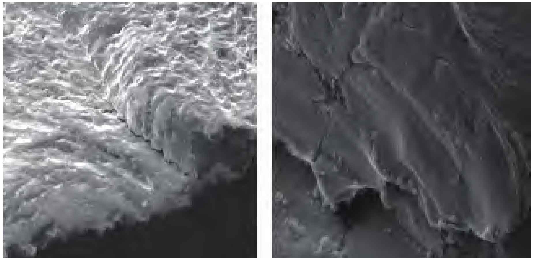
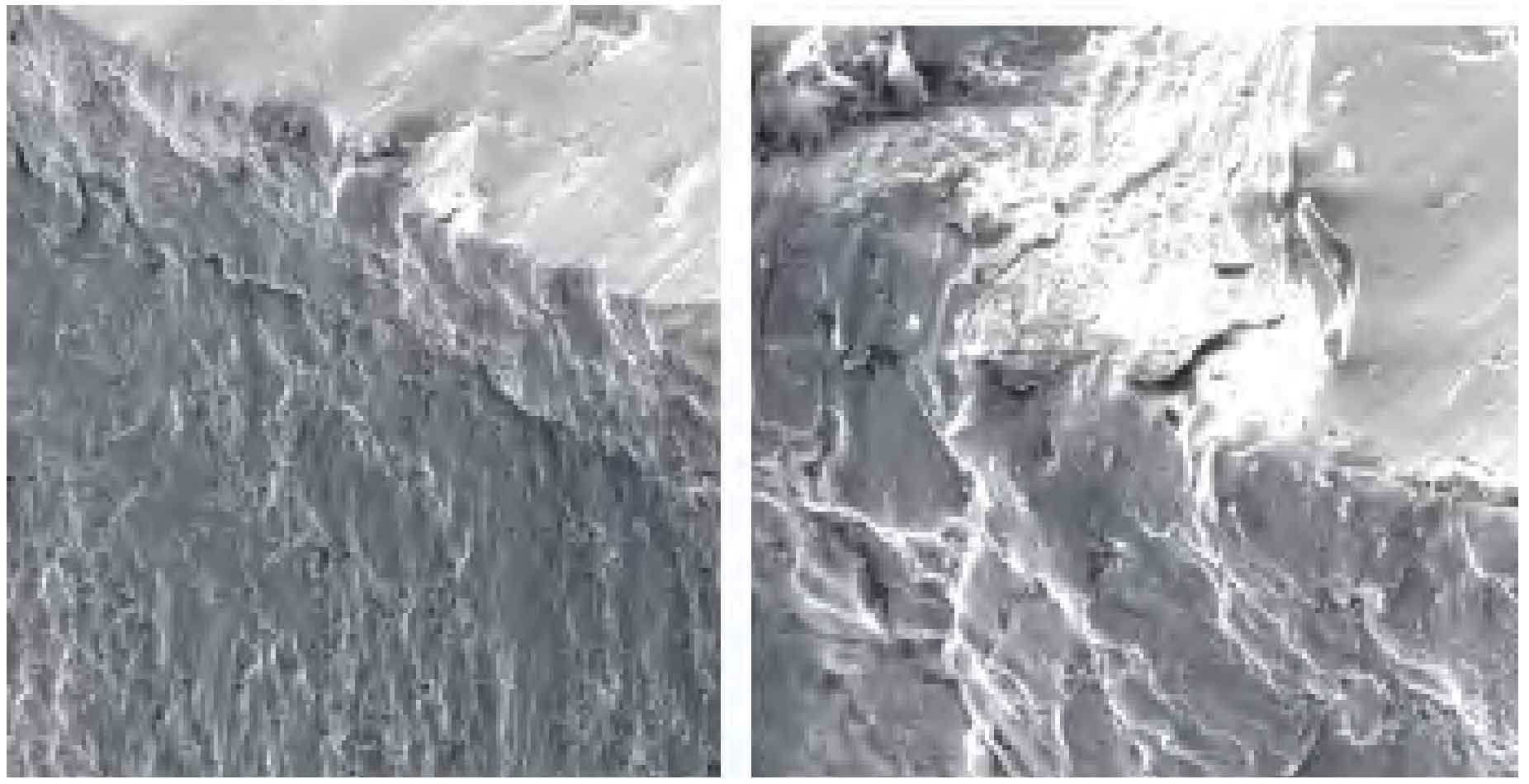
The fracture surface of bevel gear was observed by scanning electron microscope. Fig. 1 shows the SEM morphology of the fatigue source area of the bevel gear fracture surface, Fig. 2 shows the SEM morphology of the fatigue expansion area of the bevel gear, and Fig. 3 shows the SEM morphology of the transient fracture area. The fracture crack source is located at the middle and lower part of the bevel gear concave, and other secondary microcracks are also generated during the crack propagation process. Under the action of variable load stress, the microcracks are first generated at the surface near the tooth root of the meshing surface of the central contact area of the bevel gear concave, and the tooth surface of the bevel gear collapses and peels off. Then the crack propagated to the center in herringbone pattern, and finally broke at the shear lip, with obvious dimple quasi cleavage morphology features in the central instantaneous fracture zone. No obvious inclusions and second phase defects are found on both sides of the crack.
The fracture property of bevel gear is determined as contact fatigue crack.
1) The fracture crack source of bevel gear is located in the middle and lower part of the concave surface of the gear, and other secondary microcracks are generated during the crack propagation process.
2) The micro morphology of the crack source is contact fatigue, and the micro morphology of the center is dimple plus cleavage.