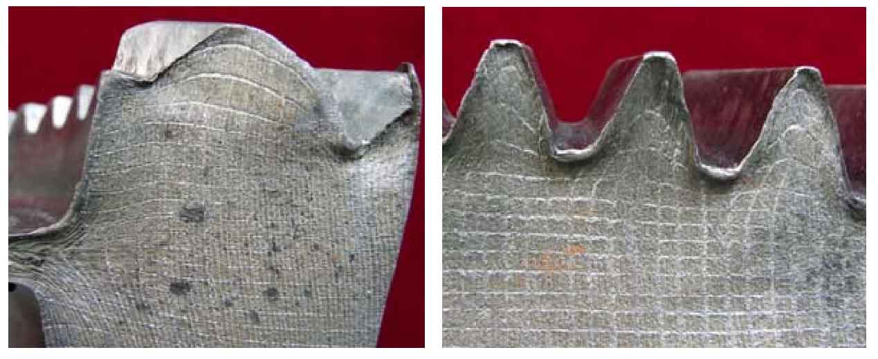
Figure (a) is the sectional grid diagram of some forgings before precision forging of driven spiral bevel gear, figures (b) and (c) are the front view and tooth profile enlarged view of some gears after precision forging of driven spiral bevel gear, figure (d) is the tooth profile grid diagram of cross section of forged gear, and figures (e) and (f) are the enlarged grid diagram of longitudinal section and cross section of tooth profile respectively.
(E) and (f) in the figure intuitively show the metal flow law of precision forging of driven spiral bevel gear forging. It can be seen from figure (f) that under the action of the tooth top of the spiral bevel gear tooth die, the metal longitudinal lines in contact with it are compressed and stretched laterally, and finally form the tooth root part of the forging. During the forming process, the metal is forced to flow to the cavity of the gear die to form the tooth top part of the forging. Except for the metal near the tooth shape, the mesh in the middle and bottom of the spiral bevel gear is almost free of deformation, that is, the metal flow deformation is very small, because the deformation is mainly concentrated in the tooth shape. In addition to filling the tooth cavity, part of the metal on the upper part of the blank is squeezed into the inner ring of the spiral bevel gear at the contact gap between the boss of the punch and the die, and the other part forms a flash. From the grid deformation area in figure (d), it can be seen that the whole deformation occurs at the upper end face of the forging. The measured height of the deformed dimensions at the middle and lower end faces is slightly less than 2mm and the width is slightly greater than 2mm, indicating that there is little or no deformation at this part. Therefore, the forming of driven spiral bevel gear can be considered as a local deformation process.
From the forming figures (d), (e) and (f), it can be seen that the forming process of the tooth shape part can be regarded as the transfer process from the metal in contact with the tooth top of the spiral bevel gear die to the cavity in contact with the tooth of the spiral bevel gear die. With the continuous increase of the amount of reduction and metal transfer, the metal flow speed becomes more and more intense, and the tooth cavity is filled until it is completely formed. As the tooth cavity section is gradually reduced, the flow resistance of metal in the process of filling the tooth cavity is also increasing, which is manifested in the increasing deformation force, which can be seen from the simulated load stroke curve.
Compared with the previous numerical simulation, the flash of the lead forging obtained from the physical experiment is larger, because the die is mainly designed under the hot forging condition of the steel blank, and the temperature of the die is corrected, while the forming of the lead specimen is carried out at room temperature, resulting in a large gap between the male and female dies, so as to obtain the lead specimen with larger flash.
Through the grid test of lead blank, the metal flow law and tooth filling of each part of driven spiral bevel gear in the forming process are analyzed and studied. Compared with the forming process of numerical simulation spiral bevel gear, the accuracy of numerical simulation is verified and the metal flow law is obtained.


