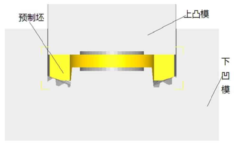
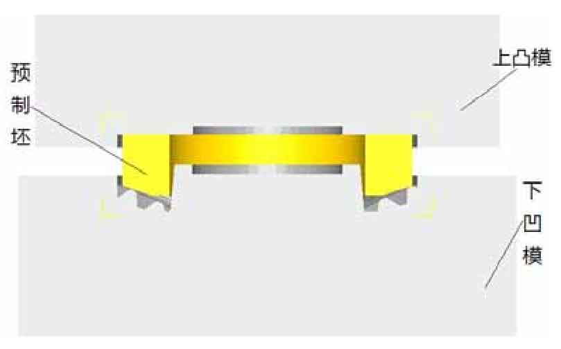
Because DEFORM-3D software does not have the function of 3D modeling, UG modeling software is used to establish the solid model. After exporting the established solid model into STL graphics, it is imported into DEFORM-3D software to generate the model. In the precision forging process of spiral bevel gear, the die and preform can be simplified into upper punch, lower die and blank to improve the speed of numerical simulation, effectively save the simulation time and ensure the accuracy of simulation results.
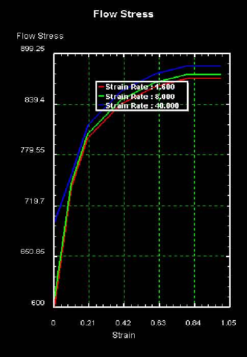
1) Material selection: in order to make the metal flow stress characteristics in the simulation process basically consistent with the real characteristics of materials, we choose the flow model in DEFORM-3D. The formed gear is made of 20CrMo material, which belongs to alloy structural steel. Because the precision forging of spiral bevel gear belongs to plastic forming, only its plastic deformation characteristics are studied, and the elastic deformation process is ignored. The flow stress curve of the material is shown in Figure 1.
2) Temperature and speed setting: in this paper, the spiral bevel gear is forged by hot forging. The preform is set as a plastic body, and the initial temperature is 1100 ℃; The upper punch and lower punch are set as rigid bodies, the upper punch is used as the driving part, the pressing speed is v = 200mm / s, and the temperature is set as 80 ℃; The lower die is fixed and the initial temperature is 80 ℃.
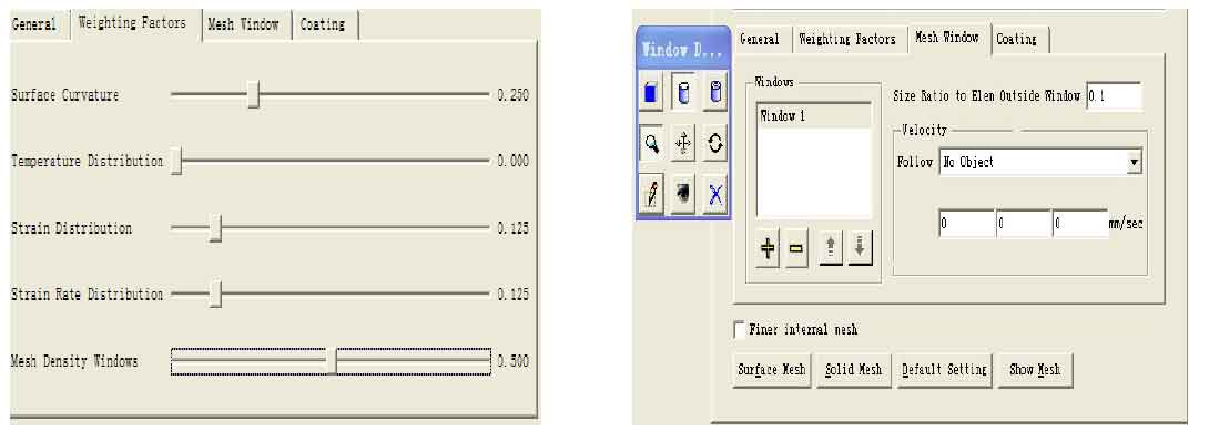
3) Mesh division: when using DEFORM-3D finite element simulation software for numerical simulation, the mesh division thickness of preform is closely related to the accuracy of data obtained in post-processing, and directly affects the final forming quality. During precision forming of spiral bevel gear, the part with the greatest change is mainly concentrated in the forming area of tooth profile. Therefore, the mesh division method in DEFORM-3D software is used to refine the local mesh of preform. Firstly, the preform is initially divided by the relative meshing method, and then the mesh of the formed tooth shape area of the preform is locally refined. In order to achieve more accurate numerical simulation results, 150000 grids are selected to refine the preform locally. As shown in Fig. 2, the parameter setting of local mesh refinement of preform (shown in Fig. 2-A) and the effect drawing after refinement (shown in Fig. 2-B) are shown.
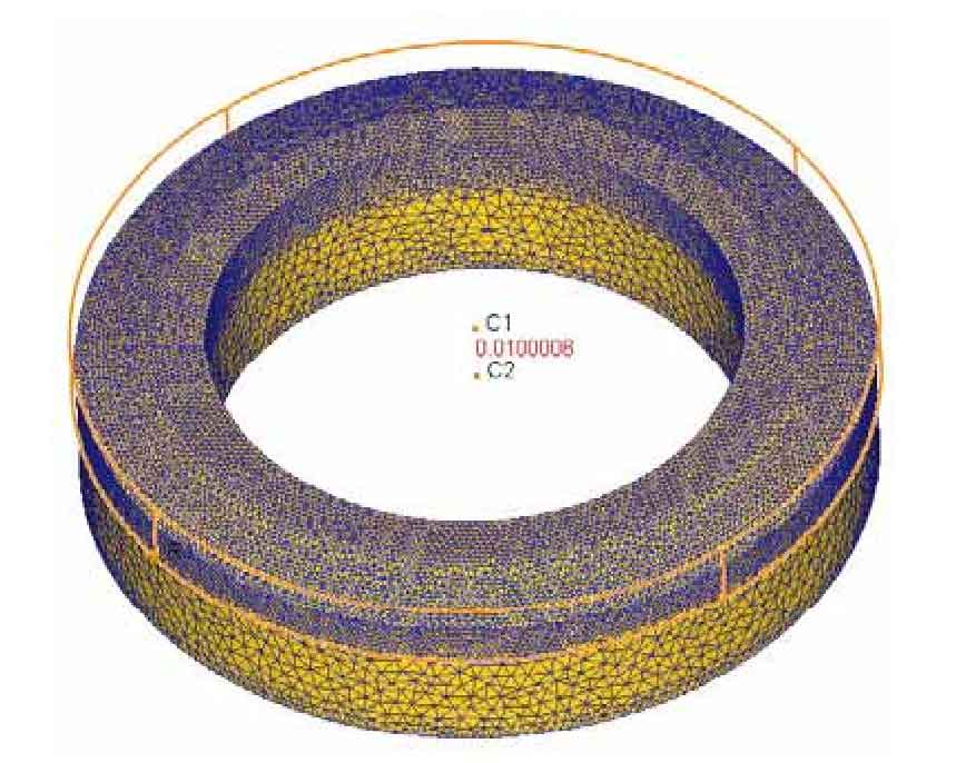
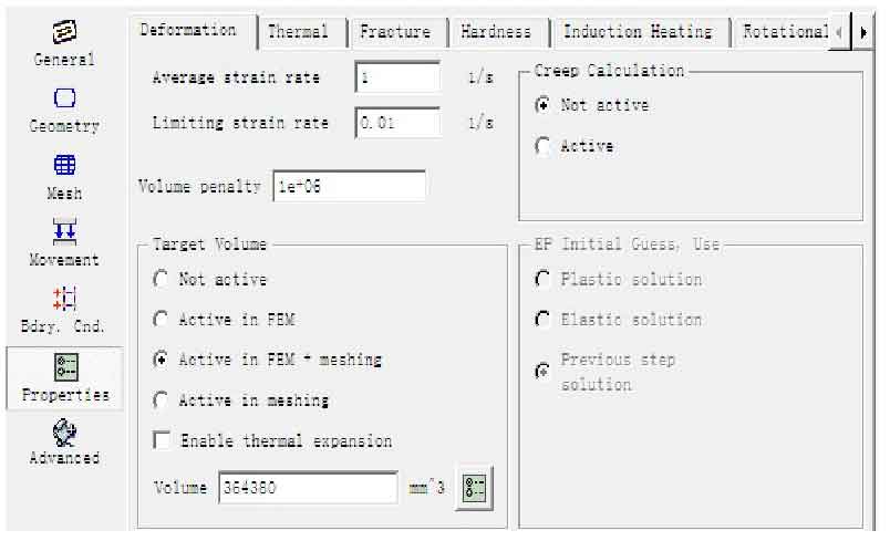
(4) Volume compensation setting: during the simulation processing stage of DEFORM-3D finite element numerical simulation software, with the deformation of preforms to varying degrees, the mesh is also being refined again. This process will cause varying degrees of volume loss, which violates the principle of constant volume. In order to minimize the volume loss, the method of volume compensation should be adopted to prevent the volume loss. In the software, meshing + femin active is selected to compensate the volume according to the initial volume. As shown in Figure 3, the volume calculated by pretreatment is 364380 mm3.
5) Solution and iterative method selection: in DEFORM-3D software, solver provides three solution methods, namely conjugate gradient method, sparse method and GMRES (applicable to multi CPU mode). Iteration method provides two iterative methods, namely direct iteration method and Newton Raphson method. Considering the operation speed and computer hardware configuration, spark and Newton Raphson are selected for finite element simulation analysis.
6) Setting of hot die forging process: in this paper, hot forging is selected to form the tooth shape of spiral bevel gear. This forging process is a non isothermal hot die forging simulation process. In the simulation process, under the condition of simulating the die forging process, the heat conduction process should also be considered. Therefore, the simulation can be divided into the following three stages:
The first simulation stage – the process of taking the workpiece out of the heating furnace and directly transferring it to the mold after heating. The time is set to 10s as the moving process in the air. This stage is to transfer heat energy to the external environment, and the workpiece energy is lost.
The second simulation stage – heat conduction process, the workpiece moves to the lower die. Before forging, the time to stay on the lower die is set as 3S. In this stage, the workpiece not only conducts heat with the external environment, but also with the lower die.
The third simulation stage – die forging process, the workpiece is forged under the action of upper and lower dies.
Because the tooth profile of spiral bevel gear is arc-shaped, the model is not axisymmetric, and a part can not be taken for numerical simulation in order to reduce the time required for simulation, so the whole should be taken as the model for numerical simulation analysis. Fig. 4 and Fig. 5 are the sectional diagrams of the internal split and double split finite element models respectively.