
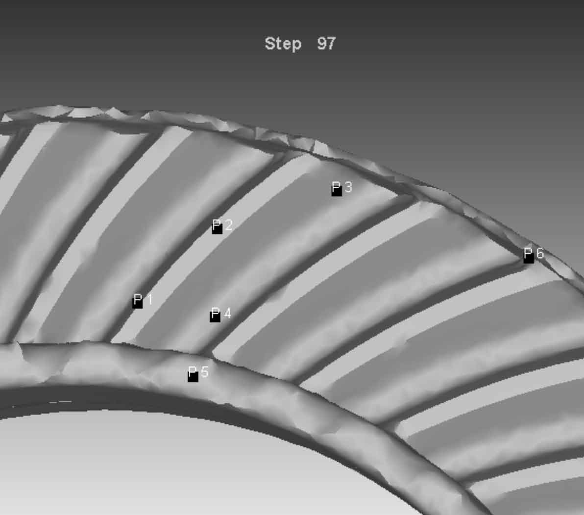
In order to analyze the material flow and stress conditions at different positions of forged spiral bevel gear, six points at different positions are selected for analysis, as shown in Figure 1. P1 selects the convex surface of gear tooth close to the small end, P2 selects the middle position of gear top, P3 selects the concave surface of gear tooth close to the large end, P4 selects the position where the bottom of gear groove close to the small end and P5 produces longitudinal flash, P6 is a point on the side of the spiral bevel gear. The damage analysis is carried out on the six position points, and the results are shown in Figure 2.
From Fig. 1 to Fig. 2, different positions in the forging process are selected and the state analysis is carried out, from which the damage in the forming process can be obtained. From the damage of the blank at different positions, the damage at the gear tooth is small, the damage at the longitudinal flash is large, and the material flow is large, resulting in a large damage rate. It can be seen from the equal effect variation diagram, The difference of the equivalent strain of the gear teeth is small, but it is obviously larger than that of other parts of the spiral bevel gear, which shows that the main stress position of the spiral bevel gear during forging is at the gear teeth. The distribution of the maximum principal stress at different points of the gear teeth can be seen from the maximum principal stress diagram, and the maximum principal velocity diagram depicts the material flow direction and flow rate at different positions.
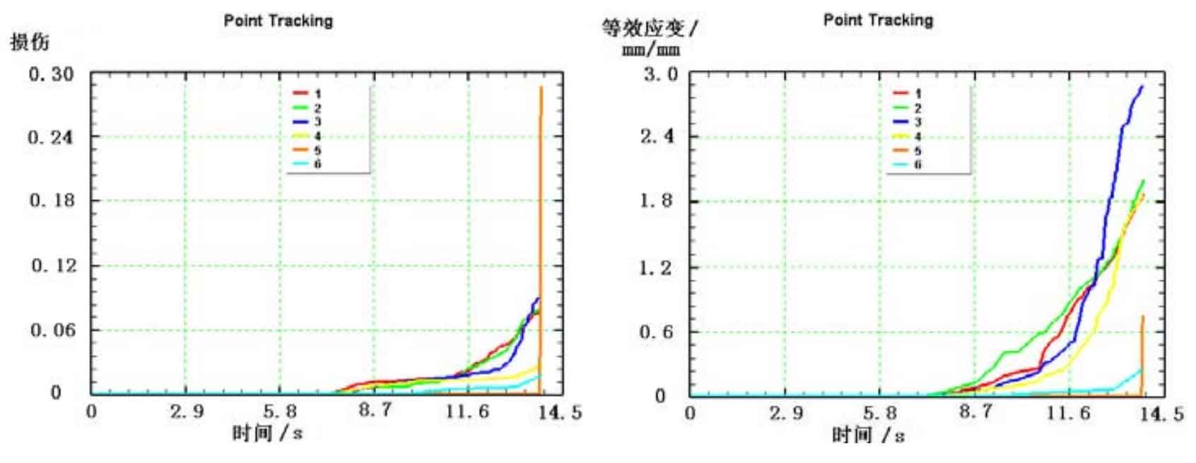
(b) 6-point equivalent effect variation diagram of gear – hot forging
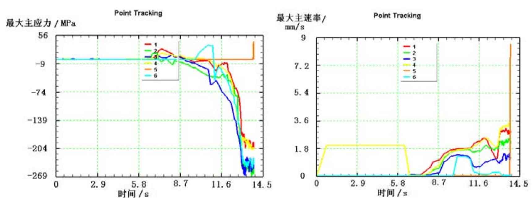
(d) Gear 6-point maximum principal speed diagram – hot forging
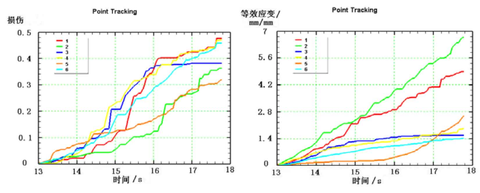
(f) 6-point equal effect variation diagram of gear – cold finishing
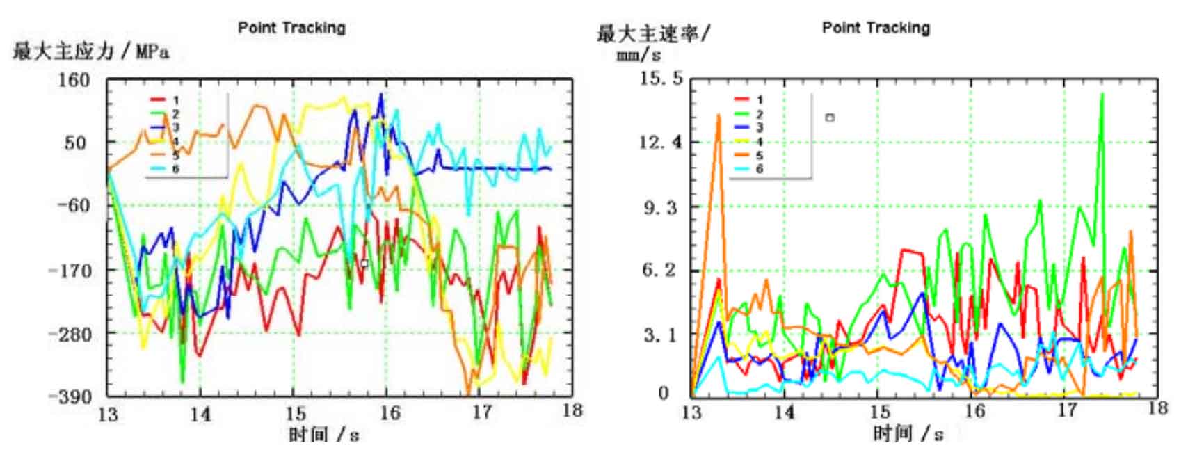
(h) Maximum principal speed diagram of tooth surface at 6 points – cold finishing
On the whole, the changes of various states such as damage in the hot forging process of spiral bevel gear are relatively gentle, while the curve in the cold finishing process fluctuates greatly, which shows that the deformation resistance and elasticity of the blank during cold forging are good, resulting in significant fluctuations in equivalent strain, maximum principal stress and maximum principal rate, and also the main differences between the hot forging and cold finishing process of spiral bevel gear.