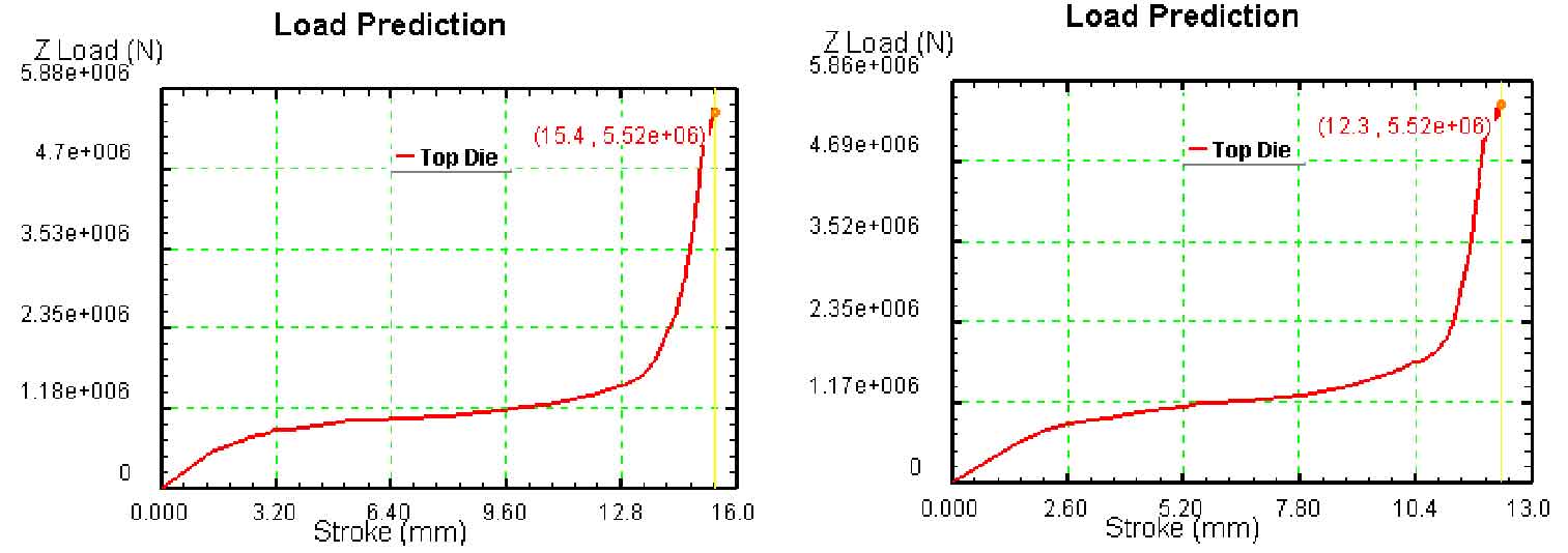
The figure shows the travel load curves of five blank size schemes, in which (a) (b) (c) (d) (E) correspond to the travel load curves of five groups of simulation experiments with inner diameter of 125 mm and outer diameter of 160 mm, 165 mm, 170 mm, 175 mm and 180 mm respectively.
It can be seen from the figure that the load trend is basically the same in the whole forming process of spiral bevel gear. For figure (a) (b) (c) (d), the corresponding blank outer diameters are 160 mm, 165 mm, 170 mm and 175 mm respectively. These blank outer diameters are less than the outer diameter of the bottom of the spiral bevel gear pre forging. Therefore, the blank contacts the upper surface of the lower die before the upper die moves. With the downward movement of the upper die, the die and blank contact and squeeze each other, the blank deforms, and the metal part of the blank flows into the tooth shaped cavity, Upsetting deformation occurs at the same time. At this time, the deformation is mainly upsetting. The stroke load curve shows a linear increasing trend, and the increase is stable and slow until the end of upsetting.

(b) Stroke load curve with a blank outer diameter of 165 mm

(d) Stroke load curve with billet outer diameter of 175 mm
With the continuous downward movement of the upper die, a large number of spiral bevel gear blanks quickly flow into the tooth cavity of the upper die and start the tooth forming process. In this process, the load will increase rapidly by 3 ~ 5 times until the load reaches the maximum when the die is closed. For figure (E), the outer diameter of the corresponding blank is 180 mm, and the outer diameter of the blank is slightly larger than the outer diameter of the bottom of the pre forging. Therefore, the lower surface of the spiral bevel gear blank does not contact the upper surface of the lower die, but contacts the inclined side of the lower die. With the downward movement of the upper die, the side surface of the spiral bevel gear blank is extruded first. At this time, the deformation load is very small until the spiral bevel gear blank contacts the upper surface of the lower die, The law is basically the same as that of the previous groups. If the table shows the maximum load of five spiral bevel gear blank size schemes, it can be seen from the table that the maximum load values of the five schemes are basically the same, and the maximum load occurs when clamping, which proves that the maximum load has nothing to do with the blank size.
| Blank outer diameter (mm) | 160 | 165 | 170 | 175 | 180 |
| Maximum load (KN) | 5400 | 5410 | 5520 | 5520 | 5560 |
However, in the upsetting process, the forming load obviously increases with the increase of blank size. The main reason for this phenomenon is that in the precision forging process of spiral bevel gear, for blanks with different sizes, due to the same die structure and smaller diameter, during the precision forging process, with the downward movement of the upper die, the metal gradually flows from the small end to the large end of spiral bevel gear, The metal flow direction can be considered to flow obliquely downward from the small end of the spiral bevel gear to the large end of the spiral bevel gear, and the movement mode of the upper die is also from top to bottom. Because the tooth cavity of the upper die is inclined, the movement of the surface of the tooth cavity of the upper die is also inclined downward, so it can be considered that the metal flow direction is basically consistent with the movement direction of the upper die, Therefore, the forming load of billet with small diameter is relatively small.

