Introduction
As an important component of engine power output, gear transmission has the advantages of compact structure, high transmission efficiency, smooth transmission, and high load capacity The advantages of high strength and long service life are widely used in aerospace, marine, automotive engineering and other fields. However, in practical situations, harsh working environments, complex operating conditions, and processing and installation errors of gear trains inevitably affect the normal operation of the gear transmission system and cause large vibrations and shocks. Tooth surface peeling failure is one of the common forms of fatigue failure in gear transmission. Research on tooth surface peeling failure is beneficial for the prevention and early diagnosis of peeling failure, which can avoid safety accidents caused by mechanical equipment failure and thus avoid significant personal and property losses. A study was conducted on the problem of tooth surface peeling failure in a certain aeroengine reducer gear. Through simulation analysis of the contact stress on the tooth surface, improvement measures were proposed, and the effectiveness of the improvement measures was verified through experiments, providing valuable reference for the design of aeroengine reducer gears.
Gear tooth surface peeling failure
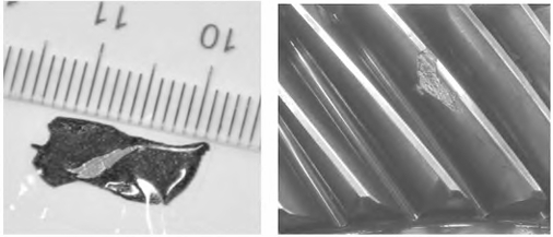
When the aeroengine reducer was tested with the complete engine for long-term testing, the detector alarm occurred. Upon inspection, it was found that the metal sheet had peeled off and separated After disassembling the reducer, it was found that one gear (driving wheel) had a 1-tooth surface peeling, as shown in the peeling morphology image.
Analysis of the causes of gear failure
One of the gear teeth in the faulty gear has obvious peeling on the working surface (marked as tooth 1), and the gear with four teeth away from tooth 1
There are pits on the working surface of the tooth (marked as 6# tooth), and the peeling position of the 1# tooth and the pit position of the 6# tooth are basically located at the center of the tooth width. In addition, all the teeth have a white bright band near the root of the tooth on the working surface, while there is no white bright band on the non-working surface.
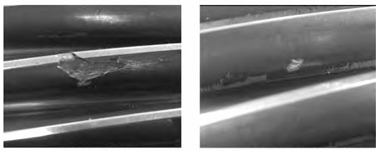
When viewed from the tooth height direction, the height of the peeling area of the 1# gear tooth and the lower boundary of the 6# gear tooth pit are basically the same, roughly at a height of about 1/3 of the tooth height from the tooth root The damage is located near the bright band on the root of the tooth, and there is a clear bright spot damage on the visible bright band along the length of the tooth. The location of the bright spot damage on the 1# and 6# gear teeth is also basically the same.
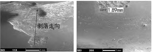
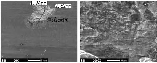
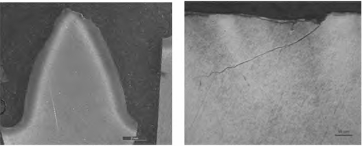
Upon microscopic observation, the peeling damage of gear tooth 1# is evident, revealing an inverted triangular shape in the peeling area, with a certain directionality in the peeling process. Based on the direction of the peeling, It can be determined that the peeling starts from the lower edge of the inverted triangle and peels towards the direction of the tooth height; there is a bright band damage area with a width of about 1.89 mm below the peeling starting position from the tooth root meshing line, and many fish scale-like microcracks can be seen along the tooth length direction in the bright band area, which extend obliquely into the matrix and are the early morphology of peeling; the tooth surface around the peeling starting area also shows more severe fish scale-like damage, and severe ones have developed into small peeling pits; while the non-meshing area of the tooth root still shows residual processing morphology and individual original pit damage in some areas, and clear fatigue characteristics can be seen in large peeling pits.
Metallurgical analysis of the spalling tooth surface includes chemical composition and metallographic structure inspection analysis. After dissection of the faulty gear, energy spectrum detection was used to analyze the composition of the spalling pit and the working area of the unspalled tooth surface on the gear tooth. The results showed that it was mainly composed of matrix components, and a small amount of foreign elements could also be detected, but no significant differences were observed. A random selection of a tooth mid-section was subjected to metallographic corrosion, and it was found that there was a clear carburized layer on the tooth surface, and the depth of the carburized layer was relatively uniform for each gear tooth. There were no significant differences in the carburized layer structure of each gear tooth, and the carburized layer structure was all hidden needle martensite + carbide. The metallographic structure of the surface of the faulty part met the requirements.
Re-examine the design of the fault gear pair of the aeroengine reducer. Conduct component simulation based on the basic parameters and structural dimensions of the gear teeth The analysis and calculation results show that the strength of the faulty gear pair meets the design requirements. Establish a system based on the real structure of the aeroengine reducer The finite element simulation analysis model is established, and the contact traces of the faulty gear pair under different design modification parameters are analyzed to simulate and analyze the fault The contact pattern of the gear pair is shown in the figure, and the design modification plan is listed.
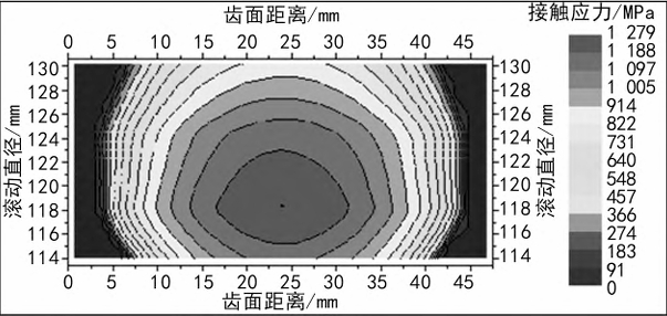
According to the simulation analysis results, if the tooth modification parameters of the faulty gear are biased towards the lower limit of the design requirements, the contact area of the faulty gear tooth surface will be heavily loaded The risk of edge contact near the lower boundary offset tooth root position and the tooth root meshing line is greatly increased.
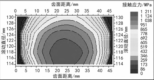
(5) During the manufacturing and assembly process review, it was found that the thermal surface treatment, actual structural dimensions, modification parameters, and tooth tip fillets during the processing of the aeroengine reducer gear were reviewed. It was found that the tooth tips of the faulty gear phase accessories (driven wheels) were all chamfered and all smaller; the modification parameters of the faulty gear (driving wheel) were within the design requirements, and the modification parameters of the faulty gear phase accessories (driven wheels) were small; the review of the assembly process records showed that after assembly, the reducer transmission was stable and the rotating parts rotated flexibly, without any abnormal noise or clamping stagnation. The contact marks of the gear pair under the measured modification parameters of the faulty gear were analyzed. According to the simulation analysis results, it was found that the measured modification parameters of the faulty gear under the contact heavy load area were consistent with the actual marks.
The faulty gear of the reducer was tested with the engine for over-torque and long-term tests. After disassembly inspection during the early stage of the over-torque test with the engine, it was found that there were contact wear marks on the working surface of the faulty gear at the position of the tooth root, and there were contact wear marks on the corresponding meshing gear at the position of the tooth tip.
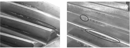
Gear fault location
Through macroscopic, microscopic, metallographic analysis and design parameter inspection of the faulty gear, as well as review of the gear testing process, the following conclusions can be drawn.
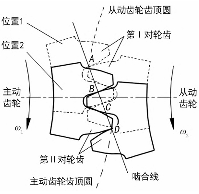
(1) The damage to the gear tooth surface is characterized by fatigue flaking, which begins near the tooth root meshing line; the gear experiences fatigue flaking at the tooth bottom meshing line, which It may be related to the local stress concentration at the meshing line of the tooth bottom when meshing with the tooth top and bottom.
(2) The actual chamfer of the tooth tip of the faulty gear phase accessory (driven wheel) is all too small, and the rounding is irregular, which is prone to producing sharp edges, resulting in a faulty gear
(Driving wheel) Edge contact occurs at the root of the teeth and the tooth tip of the meshing gear, causing initial damage to the tooth surface.
(3) The amount of tooth profile modification of the faulty gear (driven wheel) is too small, causing the contact mark of the faulty gear (driving wheel) to move towards the lower boundary of the heavy load area The position of the tooth root is expanded, resulting in interference during meshing and disengaging.
(4) The spalling of the gear tooth surface is related to the previous over-torque test. Under high load conditions, the lower boundary of the contact mark on the faulty gear tooth surface is shifted towards the tooth The root position is expanded, which is sensitive to the addendum fillet of the gears of the accessories.
(5) The lubrication of the faulty gear pair is insufficient, and the heavy load and poor lubrication further expand the damage to the tooth surface, eventually leading to tooth surface peeling.
Analysis of Contact Stress on the Tooth Surface of Gears
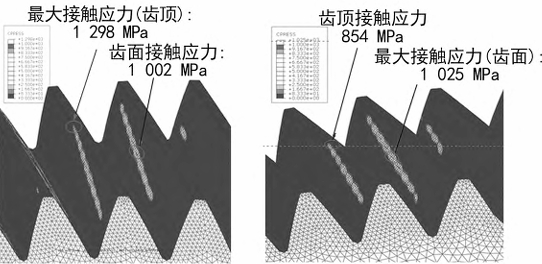
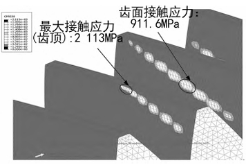
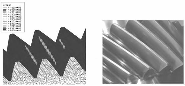
Excessively large tooth tip fillets can reduce the contact area of the gear teeth and decrease the degree of coincidence. Generally, the normal modulus is between 2.5 and 5.0, and the tooth tip fillet or chamfer is 0.1 to 0.3. The modulus of the faulty gear is 3.75. Based on the theoretical value of the faulty gear pair design, the edge contact analysis is performed on gear pairs with different tooth tip fillets, and the calculation results of the mating gears are obtained. The simulation results show that when the tooth tip fillet is R0.1, the maximum stress occurs at the tooth tip position, resulting in edge contact, and the stress increases by 29.5% compared to the tooth surface. As the tooth tip fillet increases (R0.5), the maximum stress occurs at the tooth surface position, and the tooth tip stress gradually decreases, and the contact imprint tends to be normal. According to the simulation results, if the tooth tip fillet of the gear is too small, the risk of edge contact greatly increases, which can easily lead to edge contact at the root of the faulty gear and the mating gear tooth tip position, and further expansion of contact can lead to tooth surface peeling.
Conclusion
A comprehensive analysis and investigation of the design, trial production, assembly, and testing of a gear pair with a gear tooth surface peeling failure in an aeroengine reducer were conducted, as well as failure analysis of the faulty parts. The cause of the gear tooth surface peeling was determined. Based on the cause of the failure, corresponding improvement measures were taken for the gear. After implementing the improvement measures, the gear was tested with the engine and disassembled for inspection of the failure. It was found that the gear tooth surface impression was normal, and there were no obvious abnormal conditions such as heavy contact lines and local inverted triangular micro-pitting pits at the offset tooth root position. This indicates that the failure analysis and positioning are accurate, the mechanism is clear, and the improvement measures are effective and reliable. It provides a reference value for the design of aeroengine reducer gears.
