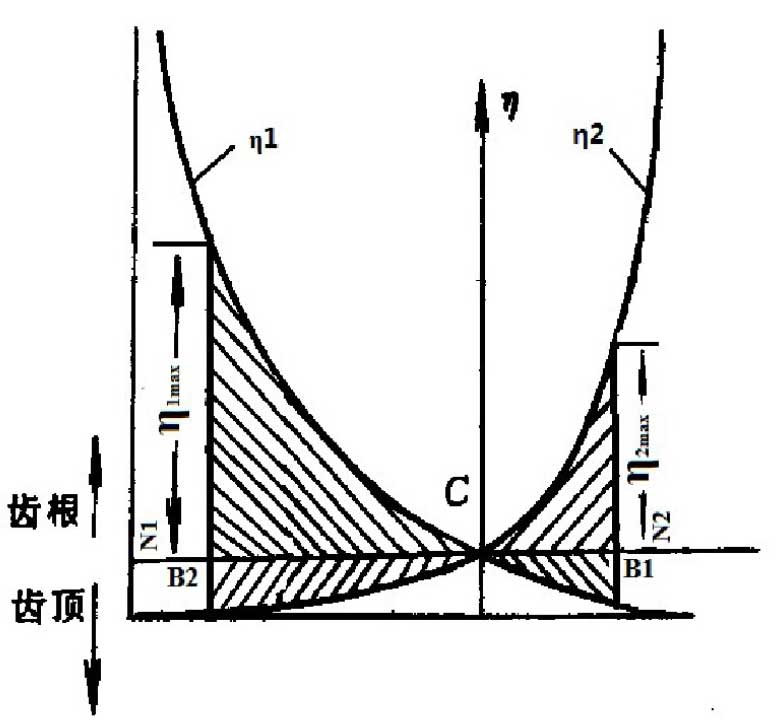
Theoretically, when k is engaged at N2, η 2 = ∞, η 1 = – 1; when k is engaged at N1, η 1 = ∞, η 2 = – 1; when k is engaged at node C, η 1 = 0, η 2 = 0.
The actual engagement line b2b1 of the gear pair is a section of the theoretical engagement line N1N2. In the actual operation of the gear, when k is meshed at point B2, the sliding coefficient η 1 of the pinion 1 reaches the maximum value; similarly, when k is meshed at point B1, η 2 of the gear 2 reaches the maximum value.

The functional relationship between the sliding rate and the position of the meshing point of the gear pair on the actual meshing line can be drawn, as shown in Figure 1.
According to the analysis:
(1) The sliding rate is a function of the position of the engagement point, and the value range is – 1 ~ ∞.
(2) The sliding rate function is a monotonic function. At the point of meshing in and out of the gear, the sliding rate of the two gears reaches the limit value respectively; and if the sliding rate at the tooth root is greater than that at the tooth top, the wear of the tooth root is more serious than that at the tooth top. At the limit point, the difference between the sliding rate of the two wheels is the largest, and the wear is the most severe.
(3) At the joint, the sliding rate of both gears is 0. At this time, there is no relative sliding between tooth profiles, which is not conducive to the formation of oil film and prone to pitting.
