1. Root cutting conditions
The root cutting phenomenon of helical gear profile is generally caused by the appearance of singularities. For small angle non orthogonal helical gear pairs, due to the small number of helical gear teeth, the small gear is prone to root cutting. Therefore, after studying the root cutting conditions, ZHY Gear assumes that the contact area equation is:

In the formula, x, y, and z are the coordinate values of the root tangent point, respectively, ρ A is the radius of the convex tooth profile of the helical gear, ea and la are the distance of movement and offset of the center of the circle, respectively, α A is the pressure angle, β Is the helix angle, ua is the axial motion displacement. Using surfaces Σ 1. Generate Surface Σ 2. Surface Σ The singularity on 2 indicates that edge biting may occur during the generation process, and its mathematical description is v (r2)=0, that is, v (r2)=v (r1)+v (12)=0, where v (r1) is the rolling speed and v (12) is the sliding speed. By using differential geometry, we can obtain:
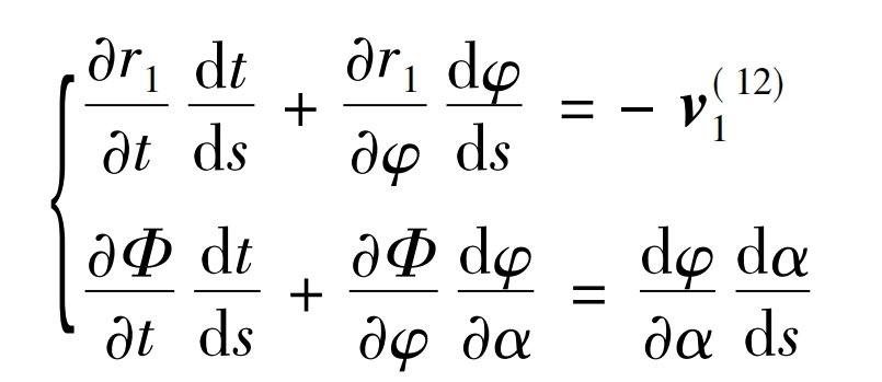
In the formula: s is the arc length parameter; Φ (t, φ,α) For envelope conditions, Φ (t, φ,α) ≡ (rt, r) φ, R α ) = 0 Can determine the surface Σ The line on the surface of 1 Σ Generating a singularity on 2 yields:
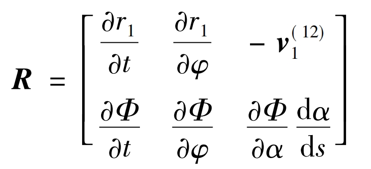
In the formula: partial r1/partial t, partial r1/partial φ、 V (12) 1 is the three-dimensional vector of spatial meshing, and v (12) 1 is the sliding speed, Φ For envelope curves. Equation (9) has two unknowns dt/ds and d φ/ Ds, and d α/ DS is known. If the matrix R in the formula is of two orders:
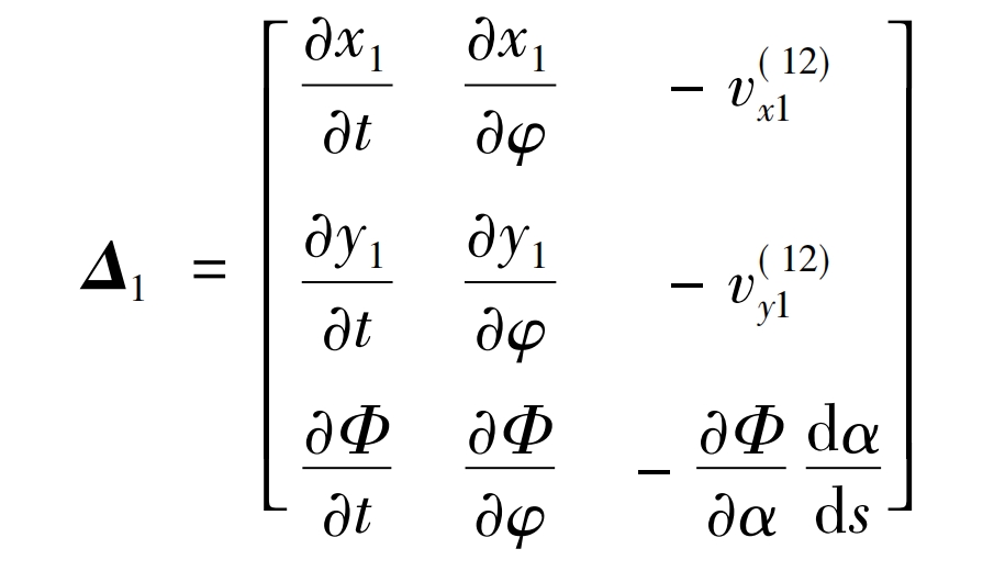
There exists a definite solution to the formula, which can be written as:
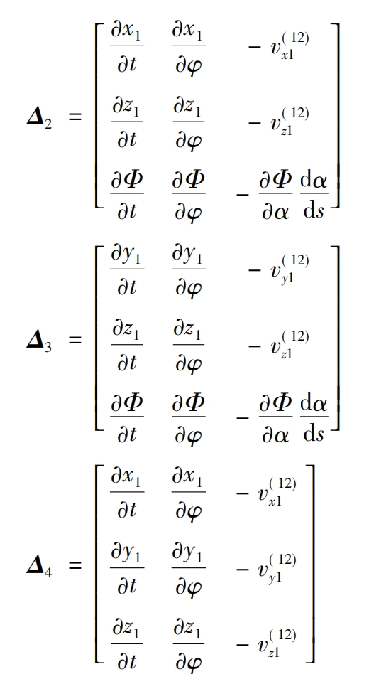
In the formula, v (x112), v (y112), and v (z112) are the coordinate components of v (12) 1, Δ 1 Δ 2 Δ 3 Δ 4 is the gradient component. Adopting Δ 1 Δ 2 Δ 3. Form a curved surface Σ The singularity condition of 2 can be expressed as:

The root cutting conditions for the helical gear tube tooth surface are obtained as follows: Δ 1=0, Δ 2=0, Δ 3=0.
2. Slip rate
Assuming there is an original curve Γ The active gear of 1 transmits motion to a conjugate curve Γ The driven gears of 2 make contact at point K, as shown in Figure 1.
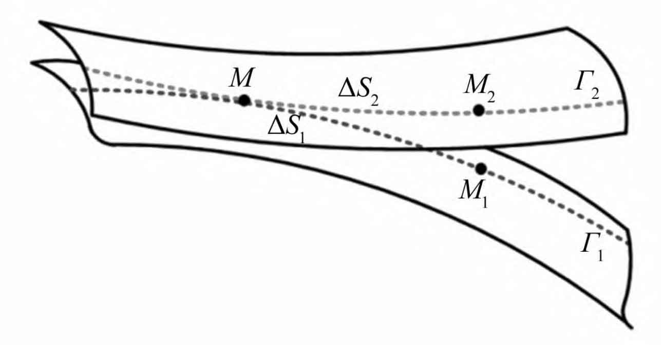
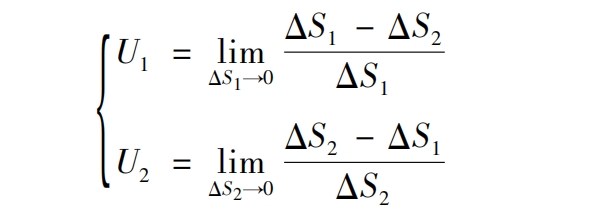
Δ S1 and Δ S2 represents respectively Δ Conjugate curve at time t Γ 1 and Γ The slip arc of 2 tends to zero during the meshing process. Assuming there is relative slip, the arc length MM1 is not equal to the arc length MM2, Δ S1 and Δ The difference between S2 is called a slip arc. The slip coefficient is the ratio of the length of the sliding arc to the corresponding arc length in the meshing area. Therefore, the calculation formula for the slip rates U1 and U2 of non orthogonal helical gear pairs with small shaft angles is:
Among them:
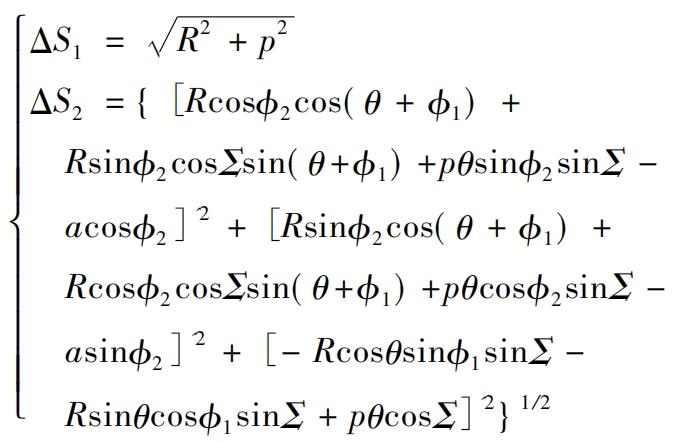
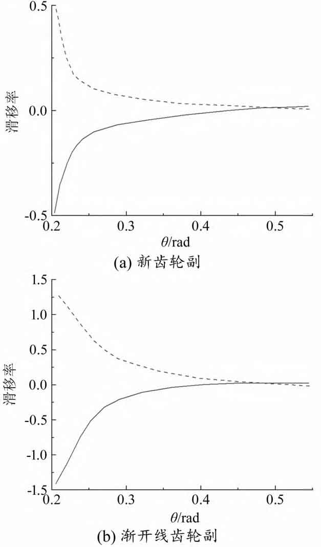
Based on the design parameters given in the table, calculate the slip ratio of the new helical gear pair, as shown in Figure 2 (a). The slip rate of a helical gear pair only changes in its sign after the node passes through zero. When the contact points near both sides begin to mesh, their sign changes due to the direction of slip velocity, and the maximum absolute value occurs at the root of the helical gear teeth meshing. At the same time, the corresponding slip rate of the transverse involute gear transmission was also calculated, as shown in Figure 2 (b). Obviously, the slip rate of the new non orthogonal helical gear pair is lower than that of involute gear transmission, which helps to improve transmission performance. The meshing process can reach the limit position and theoretically achieve approximate pure rolling contact.
| Parameters | Numerical value |
| Axis angle Σ / (°) | 15 |
| Small gear pitch radius R1/mm | 36 |
| Center distance a/mm | 136 |
| Normal modulus mn/mm | 5 |
| Pressure angle αα / (°) | 30 |
| Contact ratio i21 | 31/11 |
| Number of pinon teeth Z1 | 11 |
| Number of gear teeth Z2 | 31 |
| Spiral parameter p | 39.3 |
| Convex tooth profile radius h1/mm | 5 |
| Concave tooth profile radius h2/mm | 6 |
| Tooth width B/mm | 32 |
| Curve parameters θ / Rad | [0,0. 75] |
| Coefficient u | - 0. 58 |
| Coefficient v | - 0. 85 |
3. Stress Analysis
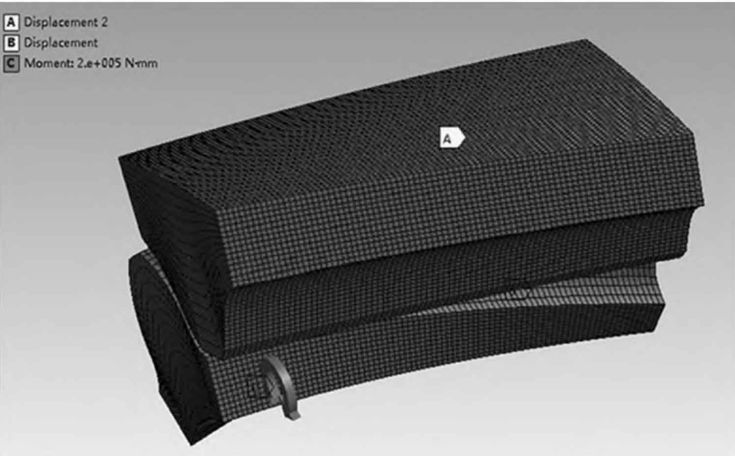
The stress analysis of the helical gear tooth profile can reflect the mechanical performance of the new helical gear transmission. The finite element model of the conjugate helical gear pair is shown in Figure 3, and the model is analyzed using ANSYS Workbench software. Based on actual meshing conditions, the Solid 185 hexahedral element is used to discretize the helical gear pair. Define the tooth profile of the small gear and the gear as the contact surface and target surface, corresponding to the CONTA 173 contact unit and TARGE170 unit, respectively.
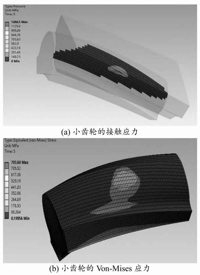
The Hertz model is used in the contact stress analysis process, and the extended Lagrangian algorithm is used for solution. The entire process uses MPC184 constraint elements. The material used for simulation is 20CrMnTi steel, with a Poisson’s ratio of 0.25 and a Young’s modulus of 205 GPa. Applying a torque value of 200 N · m to the small gear, the analysis results of the new helical gear pair are shown in Figure 4. The maximum contact stress is 1266.5 MPa, which occurs at the contact point in the middle of the tooth profile. The stress is distributed in a regular elliptical shape along the tooth width direction, and the distribution area tends to expand towards the tooth root direction. As the contact area increases, the contact stress gradually decreases, and the maximum Von Mises stress of the small gear is 793.69 MPa.
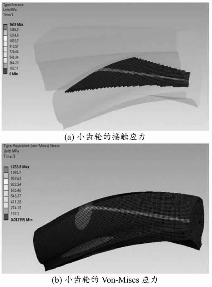
Under the same settings, the contact state and finite element analysis results of the involute helical gear pair are shown in Figure 5 as the comparison object. The maximum contact stress is 1639 MPa, which occurs at the meshing position and the stress is distributed along the contact line. The maximum Von Mises stress of the small gear is 1233.8 MPa. It can be seen that the contact stress of the new helical gear pair is significantly lower than that of the non orthogonal involute helical gear transmission, indicating that the new helical gear pair has good contact characteristics.
