
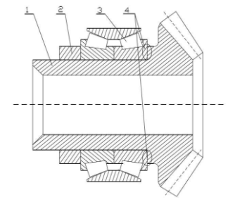
As the main power transmission mechanism, the gear shaft in the gear transmission mechanism mainly supports the rotating parts and transmits the torque. For a long time, the gear shaft is subjected to the alternating load of gear engagement force, which causes the relative micro torsional vibration of the contact surface between the gear shoulder and the bearing, resulting in the fretting wear of the gear shoulder. With the increase of fretting wear, fretting fatigue cracks appear on the contact surface, and the fretting fatigue cracks propagate with the increase of load cycles, resulting in the fracture failure of the gear shaft.
The fretting wear phenomenon of gear shoulder is very complex, which is mainly affected by the relative sliding amplitude, contact load, geometry, friction factor and many other factors, which are difficult to be measured by instruments. Therefore, in this chapter, the finite element simulation method is used to simulate the stress and deformation of the contact surface between the gear shoulder and the bearing, and the deformation amount and stress change law of the contact surface are obtained. In addition, the influence of the heat generated by the gear transmission on the thermal characteristics of the gear shaft shoulder is analyzed by using the thermo mechanical coupling method.
The gear components in the power machinery mainly bear the alternating load from the gear mesh to transmit the movement, torque or bending moment. In the process of power transmission, fretting wear occurs on the contact surface between the gear shoulder and the bearing inner ring due to the torsional vibration of the gear shaft. Severe fretting wear can cause fatigue fracture of the gear shaft.
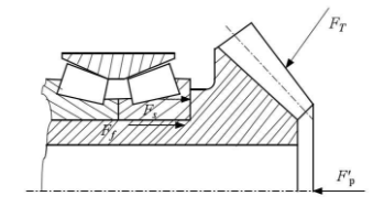
The gear transmission mechanism of complex power equipment is generally under the condition of large load. Combined with the fretting wear mechanism, it can be seen that the load is the main factor of fretting wear of parts, that is, the load condition of gear transmission mechanism has a great influence on the fretting wear of gear shoulder. In order to study the fretting wear mechanism of the gear shoulder during the operation of the gear shaft, it is necessary to analyze the force on the gear shoulder. Due to the complex forces acting on the gear shoulder, the finite element simulation method is used to analyze the stress state.
In order to get the force on the shoulder of the gear shaft in the gear transmission mechanism, it is necessary to carry out mechanical analysis on the gear components, and the results of the force analysis are shown in the figure. The gear assembly is mainly affected by three forces: the alternating load ft caused by the effect of the transmission torque, the pre tightening force FP of the nut at the gear shaft end (f ′ P in the figure is the reaction force of the pre tightening force FP of the nut at the gear shaft end) and the friction force FF of the interference fit surface between the gear shaft and the bearing.
Gear shaft is one of the most important components in power transmission of complex power equipment. When the transmission torque acts on the gear shaft, the contact surface between the gear shoulder and the bearing is slightly vibrated. With the continuous operation of the gear shaft, the contact surface of the gear shoulder will produce fretting wear. Fretting wear will cause material loss, surface morphology change, plastic deformation of surface or sub surface, resulting in fatigue cracks and reddish brown oxide wear debris on the contact surface. Serious fretting wear will lead to the fracture of gear shaft, which will cause the failure of rotating machinery.
In order to study the fretting wear condition of the gear shoulder, it is necessary to analyze the tooth force in gear engagement. In this paper, the commonly used spiral bevel gears in rotating machinery are studied. Figure 2.3 shows the stress analysis diagram of spiral bevel gears. The tooth rotation direction of the bevel gear is right, and the gear rotation direction is clockwise (from left to right). The normal force ft of tooth surface acts on the midpoint a of tooth width (point a is on the pitch cone). FT is located in the normal plane and can be decomposed into two mutually perpendicular forces FN and FF (both of which are located in the normal plane), where FN is perpendicular to OA. FF is also located in the tangent plane of the pitch cone, and the tangent is OA. In this tangent plane, FF can be divided into two forces which are perpendicular to each other, namely, the circumferential force F θ along the tangent direction and the force F γ along the nodal cone generatrix direction. The angle between F θ and f f f is the helix angle β. The normal pressure angle between the normal force ft and FF is set as α. In order to analyze the problem conveniently, the force on the gear end is divided into the following three components:
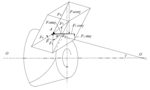
① The circumferential force F θ along the tangent direction of the gear;
② Axial force FA along the axis of the gear;
③ The radial force fr [14 direction force fr] perpendicular to the axis of the gear.